Transcription
ZL30771, ZL30772, ZL30773IEEE 1588 & Synchronous EthernetPacket Clock Network SynchronizersProduct BriefNovember 2019FeaturesOrdering Information One, Two or Three DPLL ChannelsZL30771LFG7ZL30772LFG7ZL30773LFG7 Packet and/or physical-layer frequency, phaseand time synchronization Physical-layer compliance with ITU-T G.8262,G.8261.1, G.813, G.812, Telcordia GR-1244,GR-2531-Channel2-Channel3-Channel80-lead LGA Trays80-lead LGA Trays80-lead LGA TraysNiAu (Pb-free)Package size: 11 x 11 mm-40 C to 85 C Packet-timing compliance with ITU-T G.8261,G.8263, G.8273.2 (class A, B, C, D), G.8273.4 Per-output programmable duty cycle Enables 5G wireless applications with sub100ns time/phase alignment requirements Precise output alignment circuitry and peroutput phase adjustment Programmable bandwidth, 0.1mHz to 470Hz Per-output enable/disable and glitchlessstart/stop (stop high or low) Hitless reference switching and mode switching High-resolution holdover averaging Local Oscillator Programmable phase slope limit for transients,downto 1 ns/s Operates from a single TCXO or OCXO: 23.7525MHz, 47.5-50MHz, 114.285-125MHz Per-DPLL phase adjustment, 1ps resolution Very-low-jitter applications can connect a TCXOor OCXO as the stability reference and a lowjitter XO as the jitter reference Input Clocks Accepts up to 10 differential or CMOS inputs General Features Any input frequency from 0.5Hz to 900MHz Automatic self-configuration at power-up frominternal Flash memory Per-input activity and frequency monitoring Automatic or manual reference switching Input-to-output alignment 2ns Fast lock to 1 PPS input, 30 seconds Internal compensation (1ppt) for local oscillatorfrequency error in DPLLs and input monitors Any input can be a 1PPS SYNC input forREF SYNC frequency/phase/time locking Numerically controlled oscillator behavior ineach DPLL and each fractional output divider Per-input phase adjustment, 1ps resolution Output Clock Frequency Generation Programmable Time of Day counters Any output frequency from 0.5Hz to 1045MHz(180MHz max for Synth0) Easy-to-configure design requires no externalVCXO or loop filter components High-resolution fractional frequency conversionwith 0ppm error 7 GPIO pins with many possible behaviors Synthesizers 1 & 2 have integer and fractionaldividers to make a total of 5 frequency families 1.8V and 3.3V core VDD voltages SPI or I2C processor Interface Output jitter from Synths 1 & 2 is 0.3ps RMS Power: 1.3W for 2 inputs, 1 synth, 6 LVDS out Output jitter from fractional dividers is typically 1ps RMS, many frequencies 0.5ps RMS Easy-to-use evaluation/programming software Factory programmable power-up configuration Each HPOUTP/N pair can be LVDS, LVPECL,HCSL, 2xCMOS, HSTL or programable diff.Applications Four output banks each with VDDO pin; CMOSoutput voltages from 1.5V to 3.3V Per-synthesizer phase adjust, 1ps resolution Central system timing ICs for SyncE and/orIEEE 1588, SONET/SDH, OTN, wireless basestation and other carrier-grade systemsG.8262/813 EEC/SEC, Telcordia Stratum 2-41Microsemi ConfidentialCopyright 2019. Microsemi Corporation. All Rights Reserved.Downloaded from Arrow.com.
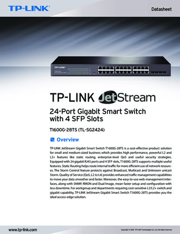
ZL30771, ZL30772, ZL30773Data Sheet1. Block DiagramRegister A ccessPACKET REF[2:0]REF0PREF0NOne Diff / TwoSingle-EndedREF1PREF1NOne Diff / TwoSingle-EndedREF2PREF2NOne Diff / TwoSingle-EndedREF3PREF3NOne Diff / TwoSingle-EndedREF4PREF4NOne Diff / TwoSingle-EndedDPLL0GP Synthesizer 0DPLL1HP Synthesizer NHPOUT7PHPOUT7Ngeneral purposelow-jitte rIntDivHP Synthesizer 2low-jitte rDPLL2FracDivReference Monitors& State MachinesXOOptional x2OSCIOSCOMCLKIN PMasterClockMCLKIN NSI SDASO ASEL1SCK SCLGPIO[8:0]CS B ASEL0RST BSRST BMicroprocessor PortSPI or I2C I/F & GPIO PinsDIVDPLL1 only present on ZL30772 and ZL30773DPLL2 only present on ZL30773Figure 1 - Functional Block Diagram2. Application Example1.544 or 2.048MHzCMOS to BITS/SSUTCXODPLL0T4 pathSynth0to BITS/SSU system1 PPS or clock w/ embedded PPSBITS/SSUGPS ol info fromIEEE 1588 algorithm15882x 156.25MHz2x 125MHzSynth1SyncE signals tosystem components155.52MHz, 161.1328125MHzor other frequency25MHzSynth21 PPS1588 signals tosystem componentsFigure 2 - Synchronous Ethernet and IEEE 1588 Central Timing Application2Microsemi ConfidentialDownloaded from Arrow.com.
ZL30771, ZL30772, ZL30773Data Sheet3. Detailed Features3.1Input Block Features 3.2DPLL Features 3.3One, two or three full-featured DPLLsVery high-resolution DPLL architectureState machine automatically transitions among freerun, tracking and holdover statesRevertive or nonrevertive reference selection algorithmProgrammable bandwidth from 0.1mHz to 470HzLess than 0.1dB gain peakingFast frequency/phase/time lock capability for 1PPS or clock 1PPS input referencesProgrammable phase-slope limiting (PSL)Programmable frequency rate-of-change limiting (FCL)Programmable tracking range (i.e. hold-in range)Truly hitless reference switching and mode switching Physical-to-physical reference switching Physical-to-packet reference switching Packet-to-physical reference switching Packet-to-packet reference switchingPer-DPLL phase adjustment, 1ps resolutionHigh-resolution frequency and phase measurementFast detection of input clock failure and transition to holdover modeHigh-resolution holdover frequency averaging, better than 0.01ppb when using 10mHz filterTime-of-Day registers: 48-bit seconds, 32-bit nanoseconds, writeable on input PPS edgeSynthesizer Features 3.4Ten input reference pins; each can accept a CMOS signal or the POS side of a differential pair; or twocan be paired to accept both sides of a differential pairAny input can be a SYNC signal for REF SYNC frequency/phase/time lockingInput clocks can be any frequency from 0.5Hz up to 900MHz (180MHz max for CMOS inputs)Supported telecom frequencies include PDH, SDH, Synchronous Ethernet, OTN, wirelessInputs constantly monitored by programmable frequency and single-cycle monitorsSingle-cycle monitor can quickly disqualify a reference when measured period is incorrectFrequency measurement (ppb or Hz) and monitoring (coarse, fine, and frequency-step monitors)Optional input clock invalidation on GPIO assertion to react to LOS signals from PHYsInput-to-input phase measurement, 1ps resolutionInput-to-DPLL phase measurement, 1ps resolutionPer-input phase adjustment, 1ps resolutionAny-to-any frequency conversion with 0ppm errorTwo low-jitter synthesizers (Synth1, Synth2) with very high-resolution fractional scaling (i.e. non-integermultiplication)Two output dividers per low-jitter synthesizer: one integer (4 to 15 plus half divides 4.5 to 7.5) and one40-bit fractionalOne general-purpose synthesizer (Synth0)A total of five output frequency familiesEasy-to-configure, completely encapsulated design requires no external VCXO or loop filtercomponentsLow-Jitter Output Clock Features Up to 16 single-ended outputs (up to 8 differential outputs) from Synth1 and Synth2Each output can be one differential output or two CMOS outputsOutput clocks can be any frequency from 1Hz to 1045MHz (250MHz max for CMOS and HSTL outputs)Output jitter from Synth1 and Synth2 integer dividers is 0.3ps RMS3Microsemi ConfidentialDownloaded from Arrow.com.
ZL30771, ZL30772, ZL30773 3.5 Operates from a single TCXO or OCXO. Acceptable frequencies: 23.75MHz to 25MHz, 47.5MHz to50MHz, 114.285MHz to 125MHz. Best jitter: 48MHz.Very-low-jitter applications can connect a TCXO or OCXO (any frequency, any output jitter) as thestability reference and a low-cost low-jitter XO as the jitter referenceThis ability to have separate jitter and stability references greatly reduces the cost of the TCXO orOCXO (no jitter requirement, no high-frequency-requirement) and allows reuse of already-qualifiedTCXO and OCXO componentsSupports redundant TCXOs connected to two REF pinsGeneral Features 3.8Two CMOS outputs from Synth0Any frequency from 0.5Hz to 180MHzOutput jitter is typically 20-30psUseful for applications where the component or system receiving the signal has low bandwidth such asa central timing ICCan output a clock signal with embedded PPS (ePPS) (duty cycle distortion indicates PPS location)Local Oscillator 3.7Output jitter from fractional dividers is 1ps RMS, many frequencies 0.5ps RMSIn CMOS mode, the HPOUTxN frequency can be an integer divisor of the HPOUTxP frequency(Example 1: HPOUT3P 125MHz, HPOUT3N 25MHz. Example 2: HPOUT2P 25MHz, HPOUT2N 1Hz)Outputs directly interface (DC coupled) with LVDS, LVPECL, HSTL, HCSL and CMOS componentsSupported telecom frequencies include PDH, SDH, Synchronous Ethernet, OTNCan produce clock frequencies for microprocessors, ASICs, FPGAs and other componentsCan produce PCIe clocksSophisticated output-to-output phase alignmentPer-synthesizer phase adjustment, 1ps resolutionPer-output phase adjustmentPer-output duty cycle / pulse width configurationPer-output enable/disablePer-output glitchless start/stop (stop high or low)General-Purpose Output Clock Features 3.6Data SheetAutomatic self-configuration at power-up from internal Flash memoryInput-to-output alignment 200ps with external feedbackFast REF SYNC locking for frequency and 1PPS phase alignment with lower-cost oscillatorGenerates output SYNC signals: 1PPS (IEEE 1588), 2kHz or 8kHz (SONET/SDH) or other frequencyJESD204B clocking: device clock and SYSREF signal generation with skew adjustmentInternal compensation for local oscillator frequency error in DPLLs and input monitors, 1ppt resolutionNumerically controlled oscillator (NCO) behavior allows system software to steer DPLL frequency orfractional output divider frequency with resolution better than 0.005pptSpread-spectrum modulation available in each fractional output divider (PCIe compliant)Seven general-purpose I/O pins each with many possible status and control optionsSPI or I2C serial microprocessor interfaceEvaluation Software Simple, intuitive Windows-based graphical user interfaceSupports all device features and register fieldsMakes lab evaluation of the device quick and easyGenerates configuration scripts to be stored in internal Flash memoryGenerates full or partial configuration scripts to be run on a system processorWorks with or without an evaluation board4Microsemi ConfidentialDownloaded from Arrow.com.
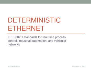
ZL30771, ZL30772, ZL30773Data Sheet4. Package Outline DrawingSYMTOTAL THICKNESSSUBSTRATE THICKNESSMOLD THICKNESSBODY SIZELEAD WIDTHLEAD LENGTHEP WIDTHEP LENGTHLEAD PITCHEP PITCHLEAD COUNTEP COUNTEDGE LEAD CENTER TO CENTERBODY CENTER TO CENTER LEADBODY CENTER TO CENTER EPPRE-SOLDERPACKAGE EDGE TOLERANCEMOLD FLATNESSCOPLANARITY5Microsemi ConfidentialDownloaded from Arrow.com.AA1A2DEWLW1L1ee1nn1D1E1SDSESD1SE1COMMON BSCBSCBSCBSCBSCBSCBSC---
Microsemi Corporate HeadquartersOne EnterpriseAliso Viejo, CA 92656 USAWithin the USA: 1 (800) 713-4113Outside the USA: 1 (949) 380-6100Sales: 1 (949) 380-6136Fax: 1 (949) 215-4996E-mail: sales.support@microsemi.com 2019 Microsemi Corporation. Allrights reserved. Microsemi and theMicrosemi logo are trademarks ofMicrosemi Corporation. All othertrademarks and service marks are theproperty of their respective owners.Downloaded from Arrow.com.Microsemi Corporation (Nasdaq: MSCC) offers a comprehensive portfolio of semiconductorand system solutions for communications, defense & security, aerospace and industrialmarkets. Products include high-performance and radiation-hardened analog mixed-signalintegrated circuits, FPGAs, SoCs and ASICs; power management products; timing andsynchronization devices and precise time solutions, setting the world’s standard for time;voice processing devices; RF solutions; discrete components; security technologies andscalable anti-tamper products; Power-over-Ethernet ICs and midspans; as well as customdesign capabilities and services. Microsemi is headquartered in Aliso Viejo, Calif., and hasapproximately 3,400 employees globally. Learn more at www.microsemi.com.Microsemi makes no warranty, representation, or guarantee regarding the information contained hereinor the suitability of its products and services for any particular purpose, nor does Microsemi assumeany liability whatsoever arising out of the application or use of any product or circuit. The products soldhereunder and any other products sold by Microsemi have been subject to limited testing and shouldnot be used in conjunction with mission-critical equipment or applications. Any performancespecifications are believed to be reliable but are not verified, and Buyer must conduct and complete allperformance and other testing of the products, alone and together with, or installed in, any endproducts. Buyer shall not rely on any data and performance specifications or parameters provided byMicrosemi. It is the Buyer’s responsibility to independently determine suitability of any products and totest and verify the same. The information provided by Microsemi hereunder is provided “as is, where is”and with all faults, and the entire risk associated with such information is entirely with the Buyer.Microsemi does not grant, explicitly or implicitly, to any party any patent rights, licenses, or any other IPrights, whether with regard to such information itself or anything described by such information.Information provided in this document is proprietary to Microsemi, and Microsemi reserves the right tomake any changes to the information in this document or to any products and services at any timewithout notice.
lead width w 0.2 0.25 0.3 lead length l 0.35 0.4 0.45 ep width w1 1.6 1.65 1.7 ep length l1 1.6 1.65 1.7 lead pitch e 0.5 bsc ep pitch e1 1.8 bsc lead count n 80 ep count n1 16 edge lead center to center d1 9.5 bsc e1 9.5 bsc body center to center lead sd 0.25 bsc se 0.25 bsc