Transcription
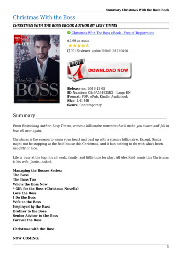
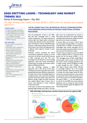
Laser Cut Like a Boss: Compliant JointsLaser Cut Like a Boss (LCLAB)is a publication created by threeundergraduate research students studying mechanical engineering. We apply a design andengineering perspective towardutilizing the laser cutter as aprototyping tool for project development. Our goal is to sharethe laser cutting techniques andprototyping processes we’veexplored in hopes of informing and inspiring our audience.We’d love to hear from you!Feel free to share your feedbackon our work as well as some ofyour own laser cutting stories.Our laser cutter: a 60W Epilog HelixThe Like a Boss philosophy is built around the central belief in the mastery of your craft,whatever you choose it to be. From blacksmithing to cooking, you are intentional withyour learning and acquisition of skills— then innovative and thoughtful in your exploratorywork. You may not know how to accomplish all facets of a task from the onset, but you havethe confidence and collection of skills to attack the problem and execute a fitting solution.
Compliant Mechanisms//Everything is a springIn this issue: What iscompliance? Materials &compliantHow to use this booklet All materials have a natural flexibility. The ability of a material to deform and return to its original shape depends on two factors: the elasticmodulus and the geometry of the piece. The elastic modulus is a quantity that describes a material’s tendency to deform elastically when aforce is applied to it. Compliant mechanisms use this natural flexibility to transfer an input force or displacement to another point.mechanismsMathematicalIn this issue, we’ll share 3 examples of laser cut compliant mechanisms:models forliving hingesIn every issue, we feature laser cutting explorations by each member of our team. These three lasertidbits are meant as aids and inspiration techniques that can be incorporated into your prototypes duringyour project development process. We also take pains to think citically about and convey our ownprototyping processes, detailing successes as well as failures. Snap-fit design Rotary snap-fitEach team member has a specific take on prototyping and exploratory work which is reflected in thestyle of our sections. The sections are color-coded so that you may differentiate between, comment on, oradapt parts of each prototyping process to your own.At the end of each section is a list of resources / citations that can be beneficial if you are interested indiving deeper into the topic. In the back is a place for your own notes & thoughts.Cantilever Snap-Fit JointRotary Snap-Fit JointLattice Hinge
MATERIAL AND DESIGN CONSIDERATIONS FOR COMPLIANT MECHANISMSMATERIAL AND DESIGN CONSIDERATIONS FOR COMPLIANT MECHANISMSELASTIC MODULUS AND YIELD STRENGTHEach material has a unique elastic modulus and yield strength. Theelastic modulus of a material is the tendency of a particular material todeform along an axis. The elastic modulus is a measure of stress (forceover a given area) over strain (extension over original length) andtherefore has pressure units (GPa in the table). A smaller value indicatesthat the material is more flexible/compliant.The yield strength of a material is the stress at which a material beginsto deform plastically (i.e. it will not return to its original configuration).It is a measure of stress and is therefore given in pressure units (GPain the table). If a material deforms plastically, it is no longer Wood (along thegrain)Douglas FirOakPineEFFECT OF GRAIN ON COMPLIANCEElastic Modulus (GPa)Yield Strength 0.03-0.050.05-0.10.05-0.1Remember that the elastic modulus is a proportion of stress over strain Note that a structure has a certain stiffness (think spring coefficient forso don’t fret when the elastic modulus of a material is greater than the a metal spring in a pen) which is determined by the structure’s materialyield strength.and geometry.When selecting a material, look for a proportionally low elasticmodulus and high yield strength.Ultimately, you need to experiment to get an intuitive sense.When creating a compliant mechanism, you will want to keep the elasticmodulus comparatively low and the yield strength high.You’ll want tooptimize the geometry by testing.We should also point out that not all materials have identical behaviorin all directions. Some materials have a grain that affects its behavior.Grain directionGrain direction has an effect on strength. This becomes particularlyimportant when creating a compliant mechanism. Compliance worksbest when the cuts are along the grain (as seen in the right partition ofthe image). When cut against the grains, they acts as shear planes andthe piece is less flexible and more likely to fail. It is also important toconsider the ply of your material. Consider which is most dominantfor your joint’s case (e.g. where is the greatest deflection, which layer isthickest, etc).
MATERIAL AND DESIGN CONSIDERATIONS FOR COMPLIANT MECHANISMSSTRESS-RELIEF TECHNIQUES IN COMPLIANT MECHANISMCertain geometries are particularly susceptible to stress concentrations. Compliance enflames the issues. Note that certain materials, such asacrylic, are far less forgiving with stress concentrations.There are various methods to reduce these stress concentrations and this is just a sampleof techniques:Lattice Hingewritten by Mary MorseAt corners, add small stress-reliefs.These can be quite small ormore dramatic.For lattice hinges, it is helpful to include stress-reliefs at the endsof cuts.
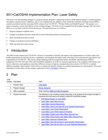
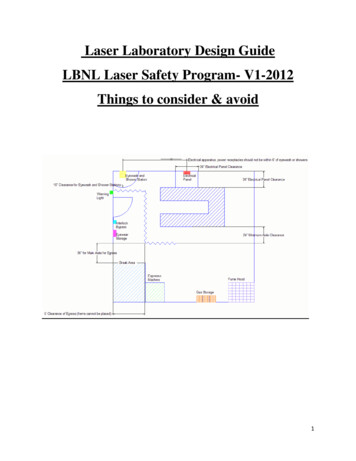
Lattice HingeApplications and VariationsA lattice hinge creates a flexible area in a piece of flat stock by removing material sothat it can bend and stretch. Lattice hinges are made up of tiny beams linked together.Each beam twists a little bit and when these little twists add together, they create a bigtwist in the material. This allows material to be very flexible. The images below demonstrate the effect in terms of compression and tension.This hinge is a part of the Magical Star Machineby Jasper Nance.View it here: in/set72157600222539663Basic Lattice HingeInfinite Corridor Technologycreated flexible, wearablecircuits by adding serpentinecuts to their PCBs. Theseoperate the same way as alattice /Michael Harwood used a largelattice hinge to create a flexible 1269/CompressionTensionDiagrams from /laser-cut-lattice-living-hinges/This lattice hinge has circlescut at the end of each slot torelieve stress concentrationsthat tend to occur at sharpcorners.This project was lasercut olio/mobius-strip/A variety of patterns can beused to add flexibility to yourmaterial. This one was createdby students at Massey Universityin New Zealand. Check out theproject here: http://www.instructables.com/id/Kerf-Table-Lamp/
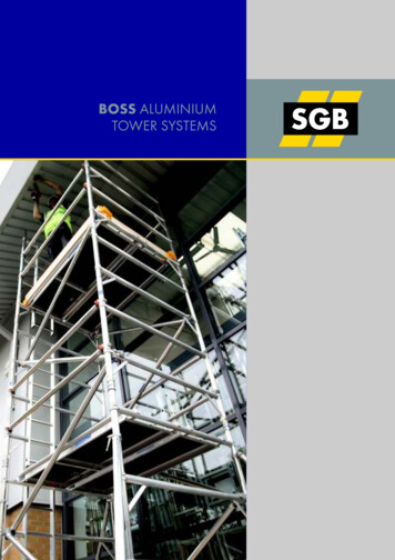
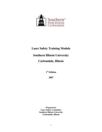
Lattice Hinge AnatomyHinge DesignLWLength of Links DoubledNumber of Links DoubledSpring Stiffness: Θmax: Spring Stiffness: sameΘ max: 1 seriesWidth of Links DoubledTL - length of linkageW - width of linkageT - material thicknessN - number of links in seriesΘ - total bend angleSpring Stiffness: Θ max: These conclusions are drawn from a mathematical model of themechanics of the living hinge.If you want a more quantitative approach to hinge design, check outthis og/2011/laser-cut-lattice-livinghinges/.
CANTILEVER SNAP-FIT JOINTSA snap-fit joint is a compliant mechanism that works by brieflydeflecting a protruding component so that it catches in adepression in another component. A common example of snap-fitjoints is the ends of K’nex toys.Cantilever Snap-fitwritten by Ingrid Hagen-KeithI decided to explore cantilever snap-fit joints. A cantilever is a beamthat is anchored on one end. Cantilever snap-fit joints are very goodfor creating perpendicular planes with your laser cut parts. Below aresome examples from plastics:
RESEARCHCANTILEVER SNAP-FIT JOINTMY PROTOTYPING PROCESSINDUSTRY USESI first looked to the examples of snap-fit joints that already existed and are widely used in industry. I found some great resources (see theback of this section for more). I used the following examples to inform and inspire my exploration of the cantilever snap sedTestsMy prototyping process was very iterative for this joint. I started with researching what already existed and then moving on to sketchesand tests. In each test, I identified a parameter that I wanted to examine (see geometry pages) and then was able to make useableconclusions. All of these activities increased my understanding of the joint.Fig. 1: The most common use of cantilever snap-fit joints is in snaplock buckles like the one above.Fig. 2: We have a toy in the lab from Protomold (if you are interested in plastics you should check them out) that includes snap-fitjoints! I got to play with them which is a great way to learn for me.
SKETCHESRESEARCHLASER-CUT EXAMPLESAfter looking through various industry resources, I decided to examine the snap-fit joint presense in laser cutting. I found some awesomeexamples that inspired me and demonstrated how creative you can be when combining joint techniques.Armed with my knowledge, I started sketching. To the left is one ofmy first sketches. I played around with three ideas and ultimatelydecided to explore two. Since this was such a big category, I knewI had to narrow my focus. So I decided to explore inward facingcantilever snap-fit joints.I found a project by Dimitris Papanikolaou from the MIT Fab Labthat was the bomb-diggity! It had snap-fit joints everywhere! Checkit out here: imitris.papanikolaou/Assignment 2.htmlThis photo was posted for a Digital Crafting Workshop focused onsnap-fit joints and really caught my eye. It creates a compliant webwhen everything is snapped together: art and craft.
A COUPLE DISCOVERIESMy experience: Acrylic is way more brittle than Delrinas you may expect based on each material’s elasticmodulus and yield strength. A Delrin assembly may fitperfectly but an acrylic assembly with the exact samegeometry will break.Prototyping insight: When prototyping a compliantmechanism, use the material you intend for the finalproduct.BASIC GEOMETRYBroad Ideaw2Subset of totyping insight: To avoid getting overwhelmed whenexploring, set a scope for yourself and narrow further asyou find things you think are interesting.2w4w3tDescriptionFunctiontthickness of fingerpiecebased on the sheetmaterial thicknessl1height gutter 1to allow for moreflexibility in whenpushing the fingertowards the centerexperiment with thislength. A greater l1 increases flexibility but reducesstrength and is not as aesthetically pleasing. I wouldsuggest you start with l1 l3l2land lengthlength of the nosefacethe nose length is determined by the intersectionof the angles and the thickness of the materaill3height gutter 2to allow for moreflexibility in whenpulling the fingertowards the centerexperiment with thislength. A greater l3 increases flexibility but reducesstrength and is not as aesthetically pleasing. I wouldsuggest you start with l1 l3l3w1BrittleMy experience: I chose a very broad subject (snap-fitjoints) and then narrowed to a sub-group (cantileversnap-fit joints). I then brainstormed a couple ofgeometries and tested my two favorites.l4Parameterw5Design Considerations
BASIC GEOMETRYBASIC ntact length offingerthe useable length of for a cleaner surface,the finger. The finger this value should bewill always be longer quite small.than the thickness ofthe matieral.2l3w1w1w4width of fingerw5w2overhang widthw3w3tslot widthDesignConsiderationsthis is the cantileverwidth of the snap fitthat can be used tocalculate forces.w1 w2.the nose is used tohold the snap-fit inplaceI like to start withw2 w1 w4. w2 shouldnot be greater thanw1 w4.the length betweenthe insides of thefingersnote: this applies toboth the fingered andreceiving ionsw4width gutter 1width of the insidegutterwhen this dimensionis larger, the finger ismore flexible but lessaesthetically pleasing.When pushing the fingertowards the center, themaximum deformation inthat direction is limitedto w4w5width gutter 2width of the outsidegutterwhen this dimensionis larger, the finger ismore flexible but lessaesthetically pleasing.When pushing the fingeraway from the center, themaximum deformation inthat direction is limitedto w52l3w1w4w3tParameterw5
FINITE ELEMENT ANALYSISBASIC GEOMETRYBACK-OF-ENVELOPE siderationstheta1slip angleangle of the leadingedge of the nosethe greater the angle, theeasier it is initially slip thereceiving part over thefingers of the fingeredparttheta2return angleangle of the underside of the nosethe greater the angle, themore reversible the joint.However, as it becomesgreater, the joints hasmore slop2l3w1w4w3tParameterw5I wanted to explore the use of back-of-the-envelopecalculations and FEA when prototyping with a lasercutter. I was able to abstract some basic calculations thatwould help inform my FEA using basic beam bedndingcalculations.v (FL3)/3EI where:v: deflectionF: loadL: length of the beamE: elastic modulusI: are moment of inertiaUse the space below as scratch paper:
FINITE ELEMENT ANALYSISFINITE ELEMENT ANALYSISHOW TO SET UP A FEA FOR THIS JOINT1. Set the material of your laser cut part by right-clicking on thematerial property of your part. Click “Edit Material” for the fulllist of materials with their properties. Activate the SolidWorksSimulation package in the Office Products tab.2. Make a new study within the Simulation package.HOW TO SET UP A FEA FOR THIS JOINT3. Click on “Fixtures” in the tab to the left. This will open the dialogueshown above. Let’s assume that the bottom face has a fixed geometry.Select “Fixed Geometry” and click on bottom face. Then click thegreen check mark.4. Click on “Force/Torque” in the tab to the left. This will open thedialogue shown above. Select an inside faces of the finger as shownabove. Set the force to that calculated with the rough calculationsyou did before. Then click the green check mark.
FINITE ELEMENT ANALYSISFINITE ELEMENT ANALYSISHOW TO SET UP A FEA FOR THIS JOINT5. Click on Mesh in the Study Tree and choose mesh and run.Because these FEAs are more for a sanity check and deal withrelatively small forces, you don’t need to worry about mesh qualitytoo much.6. Click on the part to set up a contact set. A contact set dictates thatplanes of a part cannot self-intersect. Ensure that ‘No Penetration’ isselected. Click on two faces that you do not want to intersect. Notethat you will need to set up two contact sets: one for each finger.HOW TO SET UP A FEA FOR THIS JOINT7.You may get this error message. Just click yes.8. In my first run, my parts were self-intersecting. I was soconfused because my calculations did not anticipating this. Ilearned that SolidWorks will automatically set a DeformationScale. To get an accurate representation, double-click on the boxabove and re-set the deformation scale to 1.
FINITE ELEMENT ANALYSISFINAL THOUGHTSHOW TO SET UP A FEA FOR THIS JOINTI was satisfied with what I learned while experimenting with this joint. There are manyvariations of the snap-fit joint that you should certainly explore!For the purpose of exploratory work, my prototyping method worked quite well.To see associated files (further discussion and cut files), please visit e /Ultimate tensile dulus-d or berkeley.edu/ pdf9.You’ll get your final FEA. In reality this piece was fine and didnot break after multiple uses. However, there was slight plastic (i.e.it did not return to its initial state) deformation which the FEAaccurately com/design/2007/0919 52-0-large.jpghttp://www.digitalcrafting.dk/?p e/dimitris.papanikolaou/Assignment 2.html
Rotary Snap-fitwritten by Annie ZengROTARY SNAP-FITI N S P I R AT I O N :Fig 2 Inspiration for modular,rotary, snap-fit joint fromnon-planar connection foundin “playableART Ball” bybeyond123.The rotary snap-fit is a compliant, dynamic joinery techniquewhich joins two perpendicular orparallel planes and allows rotationalmovement between such planes.The material that I used throughout development of this joint wasDelrin due to its low coefficient offriction.Fig 3 Inspiration for compliantstress relief components from“The Trebuchette” by E&M Labs.The idea for creating a compliant, rotational joint wasinspired by a modular toy we had in our lab whichallowed the user to connect and disconnect colorfulmodules that rotated with respect to one another. Aplanar geometry for stress relief was inspired by a jointdesign by E&M labs. DESIGNDEVELOPMENT
HEREISAPEEKINTOMYPROTOTYPINGPROCESS:Formation of Design Metrics* Whenfirst deciding what type of joint to do for this issue, I generated a series of sketches of existingjoints that inspired me. Then after cataloguing certain design metrics and designer goals that I wantedto fulfill with this exploration, I settled on a laser cut rotary snap-fit joint modeled after a modular toy.Design Requirements: Range of motion: allows 360 rotation of two planes with respectto one another (planes can beparallel or perpendicular) Utilizes compliance concepts toallow snug fits in joint Modular & removableDesigner Values: Develop joint via rigorous, iterative process Gain experience analyzing designs using finiteelement analysis Characterize the primary modes of failure as wellas the maximum axial load able to be sustained bythe joint Elegant, simplistic design3My take on prototyping:After developing an initialproof of concept of an idea Ihave in my head, I utilize protoyping to refine and improvemy design. I either analyzedesigns in CAD or makephysical artifacts, emphasizingspeed. I make incrementalchanges to the design, alteringone variable at a time so thateach prototype will answera specific question I have inmind.!Fig 2. The final 3D module consisted of two cross header pins per module that could link with correspondingsockets. Paper prototypes of the 3D module were created initially to determine the geometry of each planarpiece.* Testing & Characterization of Joint Geometry & Failure Modes:Iterative Process to Develop Joint:* Forthe development of this joint, I focused on small and quick iterative designs which allowed me to add increasing complexity to thesystem. This allowed me to attribute any failures to specific changes I had made and to move foward at a steady, reliable pace.12Fig 2 Analysis of design without circularcutout shows greater stress build-up. Fig 2 Prototype I was a proof of concept that explored the viability ofmimicking a spherical geometry with two flat planes. The focus was on quickdevelopment, transferring and modifying known geometries for snap-fits andstress relief into the most simple design.,Fig 2 After discovering that smooth, full rotation of the joint was possiblewith a single-plane header, I then increased the complexity of the header pinby making a cross configuration. This gave the joint greater structure andrigidity. Fig 2 Analysis of design with circular cutoutshows reduced stress build-up.Fig 2 Failure of design in axial loadingGoal / Hypothesis: Provide stress relief during deflection of compliant member (will a circular cutout at the end of the L1gap do the trick?)Experiment 1: Analyzed geometry using SolidWorks finite element analysis (FEA) to conclude that the cutout seemed likea reasonable and beneficial addition. Saved time and material from making an actual prototype.Experiment 2: Then proceeded to make a Delrin prototype and found that the geometry was indeed successful inrelieving stress along the socket face’s plane. However, it significantly reduced the joint’s ability to take axial loading (in thedirection perpendicular to the socket face) as can seen by the failure after I inserted and removed a header pin.Takeaways: It’s great to do a software analysis for quick, iterative design changes on the computer, but a physical prototypecan help you recognize failures that you did not forsee.
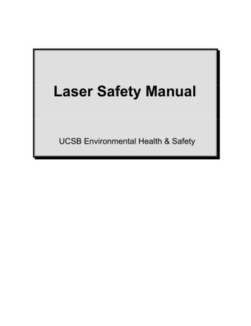
ROTARY SNAP-FIT JOINT DESIGNJOINT DESIGN CONTD. 1Compliant SocketCompliant SocketParameter Descriptiong2w1g2g1stress relief gap 2Dt1L1g1stress relief gap 1FunctionDesign Considerationprovides stress reliefand allows deflectionof compliant part toenable insertion ofheader pinGap must be wide enough to allow full insertion of widest partsof header pin: D g2 w2 L3sinα1.similar to g2Increasing g1 allows greaterease of insertion and removalof header pin. However, g1 is theonly discontinuous part of socket in which header pin rotates. Agreater gap may decrease easeof rotation.Header Pinw2w1L3Į1compliance width(maybe also controlsamount of axial loadtaken, see future explorations)controls ease ofdeflection of compliantmember for snap-fitjointt2h1L2L1stress relief lengthprovides stress reliefupon deflection ofcompliant memberParameter DescriptionLonger L1 is better for stressrelief & increases ease of deflection of compliant member.diameter of snap-fitsocketdiameter marks outa circle which allowsinsertion and rotationof header pinD can be taken to be the samelength as w2 until the ratio D/t2gets below 2. Then increase Dto a value between w2 andw22 t22 to ensure smoothness of rotation.t1thickness of socketbased on sheet material thicknessMake sure t1 h1.A greater t1means more contact betweenrotational surfaces of header pinand socket. This can constrainmotion more to decrease wobble from ideal planar rotation.However, it can also add morefriction to rotation.w2width of header pinincrease or decreaseto change overall sizeof jointGenerally you want to makesure w2 D. However, in designsin which D/t2 is small, makew2 D. See notes in appendix.L3length of wedgelength which controlsthe greatest widthof pin in conjunctionwith α1Increasing L3 makes it harder tosnap the pin into the socket, butit also ensures a tighter fit in thejoint. As the greatest width ofthe pin (w2 2L3sin α1) becomesincreasingly greater than D, thepin becomes harder to remove.g1Dt1Decreasing w1 enables greaterease of insertion of headerpin across a certain material.However, it also becomes lessof a structural member and isquicker to fail.Design ConsiderationDg2w1FunctionL1Header Pinw2L3Į1t2h1L2
JOINT DESIGN CONTD. 2Compliant SocketParameter DescriptionDesign Considerationinto my time!h1height of header pinbodycontact edge and surface between pin andsocketMake sure h1 t1.A greater h1means more contact betweenrotational surfaces of header pinand socket. This can constrainmotion more to decrease wobble from ideal planar rotation.However, it can also add morefriction to rotation.Smoothing Rotation: Right now,depending on the size of g1 theheader pin catches in the socket whilecompleting a full rotation. Maybealtering the geometry of the corners ofthe socket would smooth the rotation.Header Pinw2L2Possible Directions for Future Work:* ThingsI would have liked to explore but could not budgetMaximum axial loading:Characterize how changing w1 affectsthe maximum axial load that can betaken by the joint to see if it is fittingfor more heavy-duty applications.L1t2SNAP-FIT!I used a wedge angle of 7 because it was something thatmy peer tried out in a previousdesign. It seems that increasingα1 gives a tighter snap-fit. However, it could eventually stressthe compliant member of thesocket enough to faillure.t1h1ROTARYangle which controlsthe greatest widthof pin in conjunctionwith L3DĮ1THEwedge angleg1L3WITHα1g2w1FunctionFUNt2thickness of header pinbased on sheet material thicknessBe wary of your D/t2 ratio. Seeadditional notes in appendix.L2length of bearingsurfacesurface of header pinwhich interacts withbottom, parallel planeof socketThis bearing (contact) surface isa frictional interface. A greaterL2 may mean increased friction,but also may decrease unwanted wobble between the tworotational planes.Fig 2 Header pin and socket modules which connect to mimic modular toy by beyond123.Allows 360 , planar rotation between adjacent modules.Recall that the rotary snap-fit performs the function of a dynamic, rotational joint which allows 360 rotation between two parallel or perpendicularplanes. It converts the geometry of a joint made by nonplanar methods forcustomizable and quick fabrication on a planar cutting tool (laser cutter). Itcan be made to be removableDL1Effects of altering L1: I wish tounderstand more rigorously the effectsof shortening or lengthening L1. Rightnow, it is just a length that I knowworks. I’d like to see how much I couldreduce this length to reduce theoverall size of the joint and still ensuresucessful deflection of the compliantmember.
APPENDConfig1: Single Header PinIXNotes & Feedback:Config2: Cross Header Pin3D Pin & Socket ModulesFig 2 My cut files for each of the configurations as well as the complete module. Illustrator and SolidWorks files can be found onhttp://lasercutlikeaboss.weebly.com/ .Notes on D/t2 ratio:t2w2 D t22 w22w2Citations:1. playableART Ball: http://www.beyond123.com/pa/ball.html2. E&M labs: http://www.em-labs.com/products/trebuchetteThe rotational smoothness of this geometry is limited bythe thickness of the sheet material that is used to makethe header pin. The edges of the pin will not be able toconform perfectly to the curvature of the socket due tothe thickness unless additional pains are taken to makethis curved geometry. This will not affect the joint toomuch when the D/t2 ratio is relatively high ( 2) whenD can be taken to equal w2. However, when D/t2 2, thethickness of the header pin (t2) begins to expand thecompliant gap (g2) enough that the edges of the pin catchon the edges of the socket it comes in contact with. Inthese cases, make D a value between w2 and t22 w22.
Meet Our TeamWe are three undergraduate mechanical engineers in training. We work at the DesignRealization Lab at Olin College. We all have shared interests in fabrication, prototyping,and tea.MaryMorseMy prototyping process during this project was highly ineffective. My failurewas in exploring too many ideas and not narrowing my focus. If I were todo this over again, I would be sure to experiment with a well-defined goalso that I don’t get lost exploring lots of different ideas.While it’s not the most refined tea, I think my favorite is red rose tea. I’vecollected the figurines in each box since a was little.IngridHagen-KeithMy prototyping process was solid but scattered. I think that in the future,it will help me to create a set of questions before I begin exploring. Whilethese questions may change as I learn more, I believe it will provide thescaffolding I need to make this a more pleasant process.I’ve always loved jasmine tea because I would drink it a lot when I was littleon a hot day. In the mornings now, I love PG Tips.AnnieZengSetting design metrics and defining my own values initially as “joint enablesa range of motion” or “allows me to practice incorporating FEA into mydesign process”, respectively, allowed me to properly scope this project andremove the least necessary components when I ran short on time. Also,for each prototype, I isolated a variable that I wanted to experiment withand understand to keep things straight in my mind with increasing complexity.I normally enjoy my black teas straight, but every once in a while I like amix of Earl Grey , honey, and vanilla-flavored soy milk.Contact Usrealdesignlab@gmail.comShare your feedback on ourissue with us as well as some ofyour own laser cutting stories.We will pick a project tofeature in our next issue!For a web-compatible versionof this issue with downloadablepart and cut files, visit http://lasercutlikeaboss.weebly.com/.This issue of LCLAB wastypeset in Gill Sans MT.
Laser Cut Like a Boss (LCLAB) is a publication created by three undergraduate research stu-dents studying mechanical engi-neering. We apply a design and engineering perspective toward utilizing the laser cutter as a prototyping tool for project de-velopment. Our goal is to share the laser cutting techniques and prototyping processes we've