Transcription
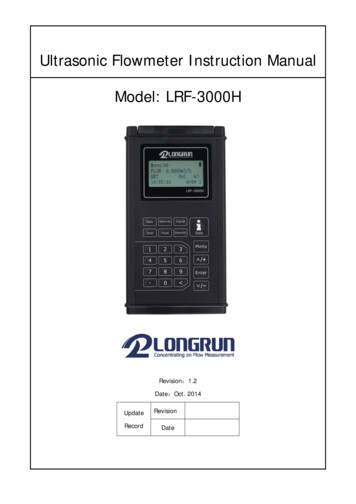
Ultrasonic Flowmeter Instruction ManualModel: LRF-3000HRevision:1.2Date:Oct. 2014UpdateRecordRevisionDate
LRF-3000H Handheld Ultrasonic FlowmeterNoticeThank you for choosing the LRF-3000H Ultrasonic Flowmeter with SLSI CMOS and low-voltage wide-pulsetransmission technology.This instruction manual contains important information. Please read carefully before operation of theflowmeter.WARNINGS IN THIS MANUALCaution and warning statements are used throughout this book to draw your attention toimportant information.WARNING“Warning” statement appears with information that is important to protect people andequipment from harm or damage. Pay very close attention to all warnings that apply toyour application. Failure to comply with these instructions may damage the meter.ATTENTIONFailure to comply with these instructions may result in faulty operation.NOTE“Note” indicates that ignoring the relevant requirements or precautions may result inflowmeter damage or malfunction.Note: Some contents in this manual maybe different from the instrument you buy, which is because of thedifferent configuration requirement when purchasing. On the other hand due to the need of the productimprovement and upgrade, there is no remark on it, please be attention to the version number and theenclosed explanation.Version: 1.2Page1 of 43
LRF-3000H Handheld Ultrasonic FlowmeterProduct ComponentsAn inspection should be made of the desired location before installing the flowmeter. Check to see if thespare parts are present in accordance with the packing list. Make sure that there is no shipping damage.If you have any questions, please contact your representative as soon as possible.Version: 1.2Page2 of 43
LRF-3000H Handheld Ultrasonic FlowmeterTable of Contents1.Electronics Installation and Connection . 51.1. Power Supply Connections . 51.1.1.Type of Power Supply . 51.1.2.Wiring . 51.2. Powering on . 51.3. Keypad Functions . 61.4. Keypad Operation . 61.5. Flowmeter Menu Descriptions . 72.Pipe Parameter Entry Shortcuts . 83.Measurement Site Selection. 104.Transducer Installation . 114.1. Installing the Transducers . 114.1.1.Transducer Mounting Methods . 114.1.2.V Method . 114.1.3.Z Method . 124.1.4.N Method (not commonly used) . 124.2. Transducers fixing . 124.3. Transducer Mounting Inspection . 134.3.1 Signal Strength . 134.3.2 Signal Quality (Q value). 134.3.3 Total Time and Delta Time . 134.3.4 Transit Time Ratio . 134.3.5 Warnings . 145.Operating Instructions . 155.1. System Normal Identification . 155.2. Low Flow Cutoff Value . 155.3. Zero Setting . 155.4. Scale Factor . 155.5. 4-20mA Current Loop Verification . 165.6. 4 20mA Current Loop Output . 165.7. 4-20mA Current Loop Verification . 165.8. SD Card Operation . 17Version: 1.2Page3 of 43
LRF-3000H Handheld Ultrasonic Flowmeter5.8.1.Specifications . 175.8.2.Install or Remove the SD card while the meter is powered on . 175.8.3.Reading the SD Data Externally . 185.8.4.SD Card Storage Operation . 185.9. ESN . 196.Window Display Explanations . 206.1. Window Display Codes . 206.2. Display Explanation . 217.Error Diagnosis . 357.1. Table 1. Self-diagnosis and Error Solutions (upon power on) . 357.2. Table 2. Error Codes and Solutions (during operation) . 367.3. Frequently Asked Questions and Answers. 378.Product Overview . 388.1Introduction . 388.2Features of Flowmeter . 388.3Theory of Operation. 388.4. Applications . 398.5. Specifications . 409.Appendix1 - Flow Application Data . 419.1Sound Velocity and Viscosity for Fluids Commonly Used. 419.2Sound Velocity for Various Materials Commonly Use . 419.3Sound Velocity In Water (1 atm) At Different Temperatures . 42Update Information:Version: 1.2Page4 of 43
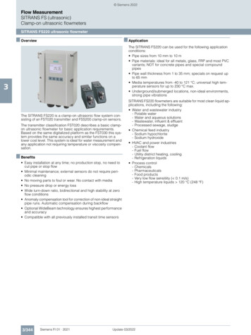
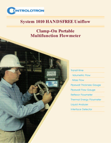
LRF-3000H Handheld Ultrasonic Flowmeter1. Electronics Installation and Connection1.1. Power Supply Connections1.1.1.Type of Power SupplyThe factory offers one rechargeable 11.1V Lithium battery and matching battery charger.1.1.2.WiringOpen the hinged top cover of the electronics. Shown from left to right on the panel of the LRF-3000H arethe downstream transducer connector, upstream transducer connector, the battery recharge port (chargethe transmitter or connect to a standby power supply), and the 4 20mA output connector.Down StreamSDUp Strea mPower Switch4-20m AChargeturn off th e power before! Pleasei nsert or pull out the SD card.Power SwitchBattery Recharge PortSD Card4 -20mA Output ConnectorU PST erWARNINGWiring connections should be made when power is off.1.2. Powering onAs soon as the flowmeter is switched on, the self-diagnosis program will start to run. If any error isdetected, an error code will displayed on the screen (see Error Diagnostics). After that, the system willrun automatically using the programmed parameters.All the parameters input by the user will be saved permanently until they are changed by the user.When the user modif ies the parameters and removes the transducers, the meter will recalculateautomatically, and operate normally under the new parameters.Version: 1.2Page5 of 43
LRF-3000H Handheld Ultrasonic Flowmeter1.3. Keypad FunctionsFollow these guidelines when using the flowmeter keypad:0 and9to input numbers.Backspace or delete characters to the left. and - Return to the last menu or open the next menu. Actsas “ ” and “-” are used to enter numbers. Select a menu. Press this key first, input a two-digit menunumber and the selected menu data will be displayed. For example,to input a pipe outside diameter, press Menu 1 1 where “11” is thewindow ID to display the pipe outside diameter. Enter Enter/ConfirmMenuDataEnter/Exit SD card storage 、.Are shortcuts to the windows for Flow Rate, POS Totalizer,Velocity, Fluid Type, Signal Quality and Diagnosis.Diagnosis1.4. Keypad OperationThe instrument setup and measurement displays are subdivided into more than 100 independent menus.The operator can input parameters, modify settings or display measurement results by “visiting” aspecific menu. These menus are arranged by 2-digit serial numbers from 00 99, then using 0, 1, etc.Each menu ID code has a defined meaning. For example, menu 11 is the pipe outside diameter, whilemenu 25 is the mounting spacing between the transducers. Each menu is discussed later in this manual.To visit a specific menu, press thekey at any time except the SD Card Storage Interface, then inputthe 2-digit menu ID code and that menu will be displayed. For example, to input or check the pipe outside1 1 keys for window ID code 11.diameter, press theMenuMenu Another method to visit a particular menu is to press the and Enter keys to scroll through themenus. For example, if the current menu is 30, press - key to enter menu 31, press the buttonagain to enter menu 30. The menus are divided into three types:1) Data Type, such as M11, M12;2) Selection Type, such as M14;3) Display Type, such as M00, M01.Visit Data Type menus to check specificparameters. If parameter change is needed, justinput the values then press Enter ; or press Enterfirst, then input the values and press Enter toconfirm.Example 1: To enter a pipe outer diameter of200mm, the procedure is as follows:1 1 to enter Menu11 (the numericalPressvalue displayed currently is the previous pipeouter diameter). Now press the Enter key. Thesymbol “ ” and a flashing cursor is displayed onthe left side of the third line on the screen. TheMenuVersion: 1.2new value can now be entered. Or input the valuefirst then press Enter to confirm 2 0 0 Enter .Menu 11Pipe Outer Diameter200 mm14:53:30Q 00RPage6 of 43
LRF-3000H Handheld Ultrasonic FlowmeterVisit Selection Type menus to check the relatedoptions. If need to modify it, press Enter first toenter the revised selection when the symbol “ ”and a flashing cursor are displayed at the left endof the third line on the screen; or input numbersdirectly to select the option when the symbol “ ”and a flashing cursor are displayed.Example 2: If the pipe material is “Stainless Steel”,1 4 to enter Menu 14, then presspressEnterto modify the option. Then, select “1.Stainless Steel” from the drop-down menu (youmay cycle through the choices by pressing the/ /andkeys) and then press ENT toconfirm the selection. It is also possible to pressthe 1 key to change the selection and wait until“1. Stainless Steel” is displayed on the second lineof the screen. Then press the ENT key to confirm.MenuMenu14Pipe Inner Diameter0.Carbon Steel14:54 :45Q 97R1.5. Flowmeter Menu Descriptions00 09Display menus: Used to display flow rate, positive total, negative total, net total, velocity,date & time etc.10 29Setup menus: Used to enter pipe outer diameter, pipe wall thickness, fluid type,transducer type, transducer mounting and spacing, etc.30 38Flow units selection and totalizer operating menus: Used to select units of measurement. Othermenus set/reset the various totalizer modes.40 45Zero Set Calibration, Scale Factor.55 83Input and output setup menus: current loop mode select, 4mA or 0mA output value,etc.90 94Diagnostics: signal strength quality (menu 90), TOM/TOS*100 (menu 91), soundvelocity (menu 92), total time and delta time of the measured signal (menu 93), Reynoldsnumber and K factor (menu 94). 0 4Appendix: Power on/off time, total working hours, on/off times etc.-04 20mA correction menu.ATTENTION“Hidden” menus are for hardware adjustment (set by the manufacturer).Version: 1.2Page 7 of 43
LRF-3000H Handheld Ultrasonic Flowmeter2. Pipe Parameter Entry ShortcutsExample: Let us assume you have a DN200 (8”) pipe, measuring water, Material is carbon steel with noliner. These parameters should be entered as follows:Step 1. Pipe outside diameter1 1 keys to enter menu 11,Pressenter the pipe outside diameter, then pressthe ENT key.MenuStep 2. Pipe wall thickness1 2 key to enter menu 12,Press theenter the pipe wall thickness (wallthickness for various pipe schedules can befound in the appendix), then press the ENTkey.Menu 11Pipe Outer Diameter200 mm14:53:30Q 00RMenuStep 3. Pipe material1 4 key to enter menu 14,Press theENT press thekey, use theorkey to select the pipe material from thedrop-down menu, then press the ENT key.Menu Step 4. Liner material parameters(including thickness and sound velocity, ifneeded)1 6 key to enter menu 16,Press the press the ENT key, use theorkey to select liner material from thedrop-down menu, and then press the ENTkey.Menu Version: 1.2Menu 12Pipe Wall Thickness6 mm14:54 :00Q 00Menu14Pipe Material0.Carbon Steel14:54 :45Q 97Menu16Liner Material0.None,14:55 :10RRNo LinerRQ 97Page 8 of 43
LRF-3000H Handheld Ultrasonic FlowmeterStep 5. Fluid type2 0 key to enter menu 20,Press the press the ENT key, use theorkey to select fluid type from the drop-downmenu, then press the ENT key.Menu Step 6. Transducer mounting methods2 4 key to enter menu 24,Press theENTpress thekey, use the or - keyto select transducer-mounting from thedrop-down menu, then press the ENT key.(Details on Charpter 4.1)MenuMenu20Fluid Type0.Water14:55 :58 Q 97RMenu24Transducer Mounting0.V14:56 :20Q 97RStep 7. Transducer spacing Press the - 2 5 key to enter menu 25,accurately install the transducer accordingto the displayed transducer mountingspacing and the selected mountingmethod.(Details on Chapter 4).Menu 25Transducer Spacing159.86mm14:56:40Q 97RStep 8. Display Mesurement Results0 1 to enter Menu 01 toPressdisplay flow rate. (Subject to the realmeasurement.)MenuVersion: 1.2Menu 01Flow30280m3/h *RVel0.3863 m/s14:43 :02Q 97 RPage 9 of 43
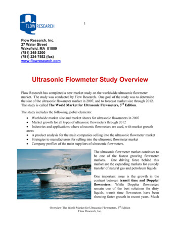
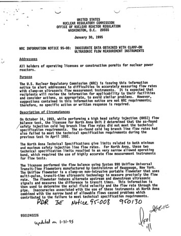
LRF-3000H Handheld Ultrasonic Flowmeter3. Measurement Site SelectionWhen selecting a measurement site, it is important to select an area where the fluid flow profile is fullydeveloped to guarantee a highly accurate measurement. Use the following guidelines to select a properinstallation site:Choose a section of pipe that is always full of liquid, such as a vertical pipe with flow in the upwarddirection or a full horizontal pipe.Ensure enough straight pipe length at least equal to the figure shown below for the upstream anddownstream transducers installation.NameStraight length of upstreampipingStraight length ofdownstream pipingL 5D90o bend10D minL 10D10D minDetectorL 10DL 50DTee0.5D min10D minL 5DL 30DDDiffuser5D minL 10DL 5DReduceL 10DL 30DValveFlow controlled upstreamFlow controlled downstreamCheck valvePumpStop valveL 50DPEnsure that the pipe surface temperature at the measuring point is within the transducer temperaturelimits.Version: 1.2Page 10 of 43
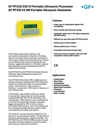
LRF-3000H Handheld Ultrasonic FlowmeterConsider the inside condition of the pipe carefully. If possible, select a section of pipe where the inside isfree of excessive corrosion or scaling.4. Transducer Installation4.1. Installing the TransducersBefore installing the transducers, clean the pipe surface where the transducers are to be mounted.Remove any rust, scale or loose paint and make a smooth surface. Apply a wide band of sonic couplingcompound down the center of the face of each transducer as well as on the pipe surface, and then attachthe transducers to the pipe with the straps provided and tighten them securely.Note:1. The two transducers should be mounted at the pipe’s centerline on horizontal pipes. Make sure that thetransducer mounting direction is parallel with the flow.2. During the installation, there should be no air bubbles or particles between the transducer and the pipewall. On horizontal pipes, the transducers should be mounted in the 3 o’clock and 9 o’clock positions ofthe pipe section in order to avoid any air bubbles inside the top portion of the pipe.3. Refer to Transducer Mounting on Menu 25.4. If the transducers cannot be mounted horizontally symmetrically due to limitation of the localinstallation conditions, it may be necessary to mount the transducers at a location where there is aguaranteed full pipe condition (the pipe is always full of liquid).4.1.1.Transducer Mounting MethodsFour transducer mounting methods are available. They are respectively: V method, Z method and Nmethod . The V method is primarily used on small diameter pipes (DN100 300mm, 4” 12”). The Zmethod is used in applications where the V method cannot work due to poor signal or no signal detected.In addition, the Z method generally works better on larger diameter pipes (over DN300mm, 12”) or castiron pipes.The N method is an uncommonly used method. It is used on smaller diameter pipes (below DN50mm,2”).4.1.2.V MethodThe V method is considered as the standard method. It usually gives a more accurate reading and is usedon pipe diameters ranging from 50mm to 400mm (2” 16”) approximately. Also, it is convenient to use,but still requires proper installation of the transducer, contact on the pipe at the pipe’s centerline andequal spacing on either side of the centerline.Side ViewUpstream TransducerSectionTop ViewTransducerFlowFlowDownstream TransducerVersion: 1.2Pipe StrapTransducer SpacePage 11 of 43
LRF-3000H Handheld Ultrasonic Flowmeter4.1.3.Z MethodThe signal transmitted in a Z method installation has less attenuation than a signal transmitted with the Vmethod. This is because the Z method utilizes a directly transmitted (rather than reflected) signal whichtransverses the liquid only once.The Z method is able to measure on pipe diameters ranging from 25mm to 1200mm (1” 48”)approximately.Side ViewUpstream TransducerSectionTop ViewTransducerFlowFlowDownstream Transducer4.1.4.Transducer SpacingPipe StrapN Method (not commonly used)With the N method, the sound waves traverse the fluid twice and bounce three times off the pipe walls. Itis suitable for small pipe diameter measurement.The measurement accuracy can be improved by extending the transit distance with the N method(uncommonly used).Side ViewUpstream TransducerSectionTop ViewTransducerFlowFlowDownstream TransducerPipe StrapTransducer Spacing4.2. Transducers fixingTransducers can stick onto the pipe with its magnetic steel racks. If need to fasten them, then can use thechains to make it firm. See below picture.2.Switch the lock-nut tofasten the chain.1.Wind the chain throughthe pipe and hang it onthe hook.Version: 1.2Page 12 of 43
LRF-3000H Handheld Ultrasonic Flowmeter4.3. Transducer Mounting InspectionCheck to see if the transducer is installed properly and if there is an accurate and strong enoughultrasonic signal to ensure proper operation and high reliability of the transducer. It can be confirmed bychecking the detected signal strength, total transit time, delta time as well as transit time ratio. Thesechecks are explained below.The “mounting” condition directly influences the flow value accuracy and system reliability. In mostinstances, apply a wide bead of sonic coupling compound lengthwise on the face of the transducer andstick it to the outside pipe wall to get good measurement results. However, the following inspections stillneed to be carried out in order to ensure a high reliability of the measurement and long-term operation ofthe instrument.4.3.1 Signal StrengthSignal strength (displayed in menu 90) indicates a detected strength of the signal both from upstreamand downstream directions. The relevant signal strength is indicated by numbers from 00.0 99.9. 00.0represents no signal detected while 99.9 represent maximum signal strength.Normally, the stronger the signal strength detected, the better the measurement.Adjust the transducer spacing to the best position and check to ensure that enough sonic couplingcompound is applied during installation in order to obtain the maximum signal strength. This isessentially fine tuning the calculated spacing shown in menu 25 (transducer spacing). It may be slightlydifferent.System normal opperation requires signal strength over 60.0, which is detected from both upstream anddownstream directions. If the signal strength detected is too low, the transducer installation position andthe transducer mounting spacing should be re-adjusted and the pipe should be re-inspected. If necessary,change the mounting to the Z method (Z has the highest signal strength).4.3.2 Signal Quality (Q value)Q value is short for Signal Quality (displayed in menu 90). It indicates the level of the signal detected. Qvalue is indicated by numbers from 00 99. 00 represents the minimum signal detected while 99represent the maximum.The transducer position may be adjusted and enough coupling used to get the signal quality detected asstrong as possible.4.3.3 Total Time and Delta Time“Total Time and Delta Time” are displayed in menu 93. The measurement calculations in the flowmeterare based upon these two parameters. Therefore, when “Delta Time” fluctuates widely, the flow andvelocities fluctuate accordingly. This means that the signal quality detected is poor. It may be the result ofpoor pipe-installation conditions, inadequate transducer installation or incorrect parameter input.Generally, “Delta Time” fluctuation should be less than 20%. Only when the pipe diameter is too small orvelocity is too low can the fluctuation be wider.4.3.4 Transit Time RatioTransit Time Ratio indicates if the transducer mounting spacing is accurate. The normal transit time ratioshould be 100 3 if the installation is proper. Check it menu 91.ATTENTIONIf the transit time ratio is over 100 3, it is necessary to check:Version: 1.2Page 13 of 43
LRF-3000H Handheld Ultrasonic Flowmeter(1) If the parameters (pipe outside diameter, wall thickness, pipe material, liner, etc.)have been entered correctly,(2) If the transducer mounting spacing is accordance with the display in menu 25,(3) If the transducer is mounted at the pipe’s centerline on the same diameter,(4) If the scale is too thick or the pipe mounting is distorted in shape, etc.4.3.5 Warnings1.Pipe parameters entered must be accurate; otherwise the flowmeter will not work properly.2.During the installation, apply enough coupling compound to bond the transducer onto the pipewall. While checking the signal strength and Q value, move the transducer slowly around themounting site until the strongest signal and maximum Q value are obtained. The larger the pipediameter, the more the transducer may have to be moved.3.Check to be sure the mounting spacing is as calculated in menu 25 and the transducer ismounted at the pipe’s centerline on the same diameter. Note that you can adjust the spacingslightly as described above to fine tune the device.4.Pay special attention to those pipes that formed by steel rolls (pipe with seams), since such pipeis always irregular. If the signal strength is always displayed as 0.00, that means there is nosignal detected. Thus, it is necessary to check that the parameters (including all the pipeparameters) have been entered accurately. Check to be sure the transducer mounting methodhas been selected properly, the pipe is not worn-out, and the liner is not too thick. Make surethere is there is indeed fluid in the pipe or the transducer is not very close to a valve or elbow,and/or there are not too many air bubbles in the fluid, etc. Once you have ruled out all thesepossible reasons, if there is still no signal detected, the measurement site has to be changed.Version: 1.2Page 14 of 43
LRF-3000H Handheld Ultrasonic Flowmeter5. Operating Instructions5.1. System Normal IdentificationPress the Menu 0 8 keys. If the letter “*R” displays on the screen, it indicates system normal.If the letter “E” is displayed, it indicates that the current loop output is over ranged by 120%. This refersto the settings in menu 57. Enter a larger value in menu 57, and the letter “E” will disappear. It can beignored if no current loop output is used.If the letter “H” is displayed, it indicates that the ultrasonic signal detected is poor. For more information,please refer to “Error Diagnosis”.If the letter “G” is displayed, it indicates that system is adjusting the signal gain prior to the measurement.Also, it means system normal. Only when the adjustment takes too long without stopping, can system beidentified as abnormal.Letter “I” indicates no signal is being detected. Check to see if the transducer wiring connections arecorrect, the transducers are securely installed, etc.Letter “J” indicates a hardware defect exists. Normally, such a defect is temporary; it could be eliminatedby system reboot (power off and restart).For further information, please refer to “Error Diagnosis”.5.2. Low Flow Cutoff ValueThe data in M41is Low Flow Cutoff Value. If the flow rate falls below the low flow cutoff value, the flowindification is driven to zero. This function can prevent the flow meter from reading flow after a pump asshut down but there is still liquid movement in the pipe, which will result in totalization error. Generally,0.01m/s is recommended to enter as the low flow cutoff point. The low flow cutoff value has no relationto the measurement results once the velocity increase over the low flow cutoff value.5.3. Zero SettingOnce zero flow occurs, a zero point is established, i.e. as the measurement value reaches zero flow, itindicates as zero. It is necessary to establish the true zero flow condition and program that set point intothe instrument.If the zero set point is not at true zero flow, an offset will occur. For an ultrasonic Flowmeter, themeasurement difference from zero point cannot be ignored under low flow conditions. It is necessary toperform a zero set calibration to improve low flow measurement accuracy.Set Zero in Menu42, press Enter ,wait for the processing indication at the bottom right corner of the screento reach“0”. Performing Set Zero with under flowing conditions may cause the flow to be displayed as “0”.If so, it can be recovered via Menu 43.5.4. Scale FactorScale factor refers to the ratio between “actual value” and “reading value”. For example, when themeasurement is 2.00, and it is indicated as 1.98 on the instrument, the scale factor reading is 2/1.98. Thismeans that the best scale factor constant is 1.However, it is difficult to keep the scale factor as “1” on the instrument especially in batch controloperations. The difference is called “consistency”.The scale factor default is “1” for each instrument prior to shipment from the factory. The reason is thatthe scale factors in the flowmeter are only limited by two parameters, i.e. the crystal oscillation frequencyand the transducer. It has no relation to any circuit parameters.During operation, if there still exists possible difference in pipe parameters, etc., the “scale factor” may benecessary to be changed when used on different pipes. Thus, scale factor calibration is specially designedVersion: 1.2Page 15 of 43
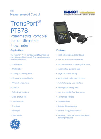
LRF-3000H Handheld Ultrasonic Flowmeterfor calibrating the differences that result from application on different pipes. The scale factor enteredmust be one that results from actual flow calibration. The scale factor can be entered via M45.5.5. 4-20mA Current Loop Verification4-20mA Blue4-20mABlack4-20mA 34124-20mA -The 4 20mA current output connects to the 4-pin din jack on the panel. The color of cable core is blue(4-20mA )and black (4-20mA-). With an accuracy of 0.1%, The current output of the FlowmeterPORTABLE is fully programmable and can be set to various output modes such as 4 20mA or 0 20mA.Use Window M55 to select the output mode.The max load of 4-20mA DC is 750Ω. Exercise care on polarity when connecting.5.6. 4 20mA Current Loop OutputWith a current loop output exceeding an accuracy of 0.1%, the flowmeter is programmable andconfigurable with outputs such as 4 20mA or 0 20mA selected in menu M55. For details, please refer to“Window Display Explanations”.In Window M56, enter a 4mA flow value. Enter the 20mA flow value in Window M57. For example, if theflow range in a specific pipe is 0 1000m3/h, enter 0 in Window M56 and 1000 in Window M57. If the flowranges from -1000 0 2000m3/h, configure the 20 4 20mA output by selecting Window M55 whenflow direction is not an issue. Enter 1000 in Window M56 and 2000 in Window M57. When flow directionis an issue, an output of 0 4 20mA is available. W
LRF-3000H Handheld Ultrasonic Flowmeter Version: 1.2 Page6 of 43 1.3. Keypad Functions Follow these guidelines when using the flowmeter keypad: 0 9 and to input numbers. Backspace or delete characters to the left. and - Return to the last menu or open the next menu. Acts as " " and "-" are used to enter numbers. Menu Select a menu .