Transcription
White PaperRFC 2547bis: BGP/MPLSVPN FundamentalsChuck SemeriaMarketing EngineerJuniper Networks, Inc.1194 North Mathilda AvenueSunnyvale, CA 94089 USA408 745 2001 or 888 JUNIPERwww.juniper.netPart Number :200012-001 03/01
ContentsExecutive Summary . . . . . . . . . . . . . . . . . . . . . . . . . . . . . . . . . . . . . . . . . . . . . . . . . . . . . . . . . . . . 5BGP/MPLS VPN Overview . . . . . . . . . . . . . . . . . . . . . . . . . . . . . . . . . . . . . . . . . . . . . . . . . . . . . 6Network Components . . . . . . . . . . . . . . . . . . . . . . . . . . . . . . . . . . . . . . . . . . . . . . . . . . . . . . 6Customer Edge Devices . . . . . . . . . . . . . . . . . . . . . . . . . . . . . . . . . . . . . . . . . . . . . . . . . 7Provider Edge Routers . . . . . . . . . . . . . . . . . . . . . . . . . . . . . . . . . . . . . . . . . . . . . . . . . . . 7Provider Routers . . . . . . . . . . . . . . . . . . . . . . . . . . . . . . . . . . . . . . . . . . . . . . . . . . . . . . . 7Operational Model . . . . . . . . . . . . . . . . . . . . . . . . . . . . . . . . . . . . . . . . . . . . . . . . . . . . . . . . 7Sample Network Topology . . . . . . . . . . . . . . . . . . . . . . . . . . . . . . . . . . . . . . . . . . . . . . . 7Control Flow . . . . . . . . . . . . . . . . . . . . . . . . . . . . . . . . . . . . . . . . . . . . . . . . . . . . . . . . . . 8Data Flow . . . . . . . . . . . . . . . . . . . . . . . . . . . . . . . . . . . . . . . . . . . . . . . . . . . . . . . . . . . 10Benefits of BGP/MPLS VPNs . . . . . . . . . . . . . . . . . . . . . . . . . . . . . . . . . . . . . . . . . . . . . . 11Challenges and Solutions . . . . . . . . . . . . . . . . . . . . . . . . . . . . . . . . . . . . . . . . . . . . . . . . . . . . . . 12Overlapping Customer Address Spaces . . . . . . . . . . . . . . . . . . . . . . . . . . . . . . . . . . . . . 12VPN-IPv4 Address Family . . . . . . . . . . . . . . . . . . . . . . . . . . . . . . . . . . . . . . . . . . . . . . 12Multiprotocol BGP Extensions . . . . . . . . . . . . . . . . . . . . . . . . . . . . . . . . . . . . . . . . . . . 13Constraining Network Connectivity . . . . . . . . . . . . . . . . . . . . . . . . . . . . . . . . . . . . . . . . 14Multiple Forwarding Tables . . . . . . . . . . . . . . . . . . . . . . . . . . . . . . . . . . . . . . . . . . . . . 14BGP Extended Community Attributes . . . . . . . . . . . . . . . . . . . . . . . . . . . . . . . . . . . . . 15Maintaining Updated VPN Routing Information . . . . . . . . . . . . . . . . . . . . . . . . . . . . . . 18Conserving Backbone Bandwidth and PE Router Packet Processing Resources . . . . 19Case Study: A Single Service Provider Backbone . . . . . . . . . . . . . . . . . . . . . . . . . . . . . . . . . . 20Distribution of VPN Routing Information . . . . . . . . . . . . . . . . . . . . . . . . . . . . . . . . . . . . 22CE Router to Ingress PE Route Distribution . . . . . . . . . . . . . . . . . . . . . . . . . . . . . . . . . 22Ingress PE to Egress PE Route Distribution Across Backbone . . . . . . . . . . . . . . . . . . 24Egress PE Router to CE Route Distribution . . . . . . . . . . . . . . . . . . . . . . . . . . . . . . . . . 28Forwarding Customer VPN Traffic Across the BGP/MPLS Backbone . . . . . . . . . . . . 29Source CE Router to Ingress PE Router Forwarding . . . . . . . . . . . . . . . . . . . . . . . . . . 30Ingress PE Router Forwarding . . . . . . . . . . . . . . . . . . . . . . . . . . . . . . . . . . . . . . . . . . . 30P Router Forwarding . . . . . . . . . . . . . . . . . . . . . . . . . . . . . . . . . . . . . . . . . . . . . . . . . . . 30PE Router to Destination CE Router Forwarding . . . . . . . . . . . . . . . . . . . . . . . . . . . . . 30Example #1: Forwarding VPN Red Traffic from Site 1 to Site 4 . . . . . . . . . . . . . . . . . 31Example #2: Forwarding VPN Red Traffic from Site 4 to Site 1 . . . . . . . . . . . . . . . . . 32Example #3: Forwarding VPN Green Traffic from Site 6 to Site 7 . . . . . . . . . . . . . . . 33Accessing the Public Internet from a VPN Site . . . . . . . . . . . . . . . . . . . . . . . . . . . . . . . . . . . . 35Non-VRF Internet Access . . . . . . . . . . . . . . . . . . . . . . . . . . . . . . . . . . . . . . . . . . . . . . . . . . 35VPN Hosts to Public Internet . . . . . . . . . . . . . . . . . . . . . . . . . . . . . . . . . . . . . . . . . . . . 36Public Internet to VPN Hosts . . . . . . . . . . . . . . . . . . . . . . . . . . . . . . . . . . . . . . . . . . . . 36Scalability of BGP/MPLS VPNs . . . . . . . . . . . . . . . . . . . . . . . . . . . . . . . . . . . . . . . . . . . . . . . . . 36Copyright 2001, Juniper Networks, Inc.
Conclusion . . . . . . . . . . . . . . . . . . . . . . . . . . . . . . . . . . . . . . . . . . . . . . . . . . . . . . . . . . . . . . . . . . . 37References . . . . . . . . . . . . . . . . . . . . . . . . . . . . . . . . . . . . . . . . . . . . . . . . . . . . . . . . . . . . . . . . . . . 38Internet Drafts . . . . . . . . . . . . . . . . . . . . . . . . . . . . . . . . . . . . . . . . . . . . . . . . . . . . . . . . . . . 38Requests for Comments . . . . . . . . . . . . . . . . . . . . . . . . . . . . . . . . . . . . . . . . . . . . . . . . . . . 38Textbooks . . . . . . . . . . . . . . . . . . . . . . . . . . . . . . . . . . . . . . . . . . . . . . . . . . . . . . . . . . . . . . . 38Copyright 2001, Juniper Networks, Inc.3
RFC 2547bis: BGP/MPLS VPN FundamentalsList of FiguresFigure 1: RFC 2547bis Network Components . . . . . . . . . . . . . . . . . . . . . . . . . . . . . . . . . . . . . . 6Figure 2: Sample BGP/MPLS VPN Network Topology . . . . . . . . . . . . . . . . . . . . . . . . . . . . . 8Figure 3: LSPs Between Site 1 and Site 2 . . . . . . . . . . . . . . . . . . . . . . . . . . . . . . . . . . . . . . . . . . 9Figure 4: Data Flow from Site 2 to Site 1 . . . . . . . . . . . . . . . . . . . . . . . . . . . . . . . . . . . . . . . . . 10Figure 5: Encoding of Route Distinguishers and IPv4 Addresses . . . . . . . . . . . . . . . . . . . . 12Figure 6: A PE Router Populates a VPN Routing and Forwarding Table . . . . . . . . . . . . . 15Figure 7: Full-mesh VPN Connectivity . . . . . . . . . . . . . . . . . . . . . . . . . . . . . . . . . . . . . . . . . . . 17Figure 8: Hub-and-spoke VPN Connectivity . . . . . . . . . . . . . . . . . . . . . . . . . . . . . . . . . . . . . 18Figure 9: Case Study: Network Topology . . . . . . . . . . . . . . . . . . . . . . . . . . . . . . . . . . . . . . . . 20Figure 10: Case Study: Label Switched Paths . . . . . . . . . . . . . . . . . . . . . . . . . . . . . . . . . . . . . 21Figure 11: Case Study: Generic Configuration for PE 1 . . . . . . . . . . . . . . . . . . . . . . . . . . . . 21Figure 12: Case Study: Generic Configuration for PE 2 . . . . . . . . . . . . . . . . . . . . . . . . . . . . 22Figure 13: Case Study: Generic Configuration for PE 3 . . . . . . . . . . . . . . . . . . . . . . . . . . . . 22Figure 14: Forwarding VPN Red Traffic from Site 1 to Site 4 . . . . . . . . . . . . . . . . . . . . . . . 31Figure 15: Forwarding VPN Red Traffic from Site 4 to Site 1 . . . . . . . . . . . . . . . . . . . . . . . 32Figure 16: Forwarding VPN Red Traffic from Site 6 to Site 7 . . . . . . . . . . . . . . . . . . . . . . . 34Figure 17: Non-VRF Internet Access . . . . . . . . . . . . . . . . . . . . . . . . . . . . . . . . . . . . . . . . . . . . . 354Copyright 2001, Juniper Networks, Inc.
Executive SummaryUntil recently, there has always been a clear distinction between public and private networks.A public network, like the plain old telephone service (POTS) or the Internet, is a collection ofunrelated systems that are allowed to exchange information freely with each other. A privatenetwork is composed of computers that are owned and administered by a single organizationthat share information with each other. Different sites in a private network are interconnectedusing dedicated leased lines to ensure that inter-site connectivity is always private. Anenterprise that deploys a private network is assured that it is the only organization using thenetwork.While deploying a single VPN service model would simplify network operations, thisapproach cannot satisfy diverse customer requirements because each subscriber is unique.Each customer has different security concerns, number of sites, number of users, routingcomplexity, mission-critical applications, traffic patterns, traffic volumes, staff networkingexpertise, and willingness to outsource network services. To satisfy a broad range of customerrequirements, service providers must offer subscribers a portfolio that contains a number ofdifferent VPN service delivery models. Over the years, a number of diverse VPN models havebeen proposed. Traditional VPNs Frame Relay (Layer 2) ATM (Layer 2) CPE-based VPNs L2TP and PPTP (Layer 2) IPSec (Layer 3) Provider Provisioned VPNs (PP-VPNs) MPLS-based Layer 2 VPNs BGP/MPLS VPNs or RFC2547bis (Layer 3)This paper focuses on developing a detailed understanding of the VPN service modelproposed in RFC 2547bis, which is generating a tremendous amount of interest in the serviceprovider community. It provides a mechanism that simplifies WAN operations for a diverse setof customers that have limited IP routing expertise. RFC 2547bis is a way to efficiently scale thenetwork while delivering revenue-generating, value-added services.Copyright 2001, Juniper Networks, Inc.5
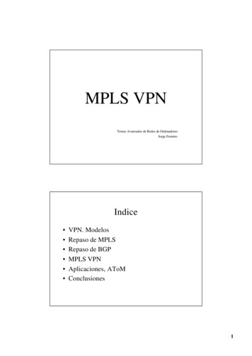
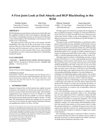
RFC 2547bis: BGP/MPLS VPN FundamentalsBGP/MPLS VPN OverviewRFC 2547bis defines a mechanism that allows service providers to use their IP backbone toprovide VPN services to their customers. RFC 2547bis VPNs are also known as BGP/MPLSVPNs because BGP is used to distribute VPN routing information across the provider'sbackbone and because MPLS is used to forward VPN traffic from one VPN site to another.The primary objectives of this approach are as follows. Make the service very simple for customers to use even if they lack experience inIP routing. Make the service very scalable and flexible to facilitate large-scale deployment. Allow the policies that are used to create a VPN to be implemented by the service provideralone, or by the service provider working together with the customer. Allow the service provider to deliver a critical value-added service that galvanizescustomer loyalty.Network ComponentsIn the context of RFC 2547bis, a VPN is a collection of policies, and these policies controlconnectivity among a set of sites. A customer site is connected to the service provider networkby one or more ports, where the service provider associates each port with a VPN routingtable. In RFC 2547bis terms, the VPN routing table is called a VPN routing and forwarding (VRF)table. Figure 1 illustrates the fundamental building blocks of a BGP/MPLS VPN.Figure 1: RFC 2547bis Network ComponentsProvider NetworkCECEPSite 1Red VPNSite 2Red VPNM40PESite 4Blue VPNCEM20M10PPM160M40PESite 3Blue VPNCECE Customer EdgeP Provider RoutersPE Provider Edge6Copyright 2001, Juniper Networks, Inc.
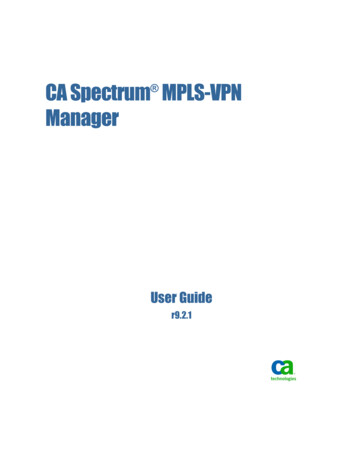
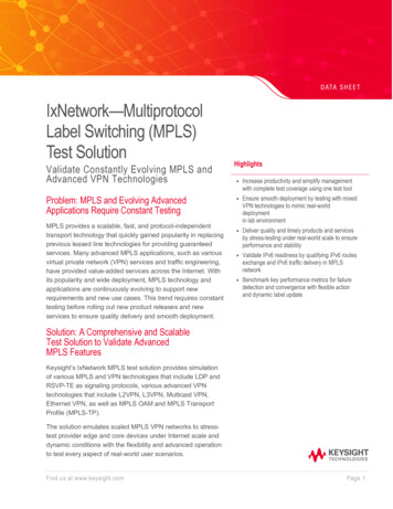
RFC 2547bis: BGP/MPLS VPN FundamentalsCustomer Edge DevicesA customer edge (CE) device provides customer access to the service provider network over adata link to one or more provider edge (PE) routers. While the CE device can be a host or aLayer 2 switch, typically the CE device is an IP router that establishes an adjacency with itsdirectly connected PE routers. After the adjacency is established, the CE router advertises thesite’s local VPN routes to the PE router and learns remote VPN routes from the PE router.Provider Edge RoutersPE routers exchange routing information with CE routers using static routing, RIPv2, OSPF, orEBGP. While a PE router maintains VPN routing information, it is only required to maintainVPN routes for those VPNs to which it is directly attached. This design enhances the scalabilityof RFC 2547bis model because it eliminates the need for PE routers to maintain all of theservice provider's VPN routes.Each PE router maintains a VRF for each of its directly connected sites. Each customerconnection (such as Frame Relay PVC, ATM PVC, and VLAN) is mapped to a specific VRF.Thus, it is a port on the PE router and not a site that is associated with a VRF. Note thatmultiple ports on a PE router can be associated with a single VRF. It is the ability of PE routersto maintain multiple forwarding tables that supports the per-VPN segregation of routinginformation.After learning local VPN routes from CE routers, a PE router exchanges VPN routinginformation with other PE routers using IBGP. PE routers can maintain IBGP sessions to routereflectors as an alternative to a full mesh of IBGP sessions. Deploying multiple route reflectorsenhances the scalability of the RFC 2547bis model because it eliminates the need for any singlenetwork component to maintain all VPN routes.Finally, when using MPLS to forward VPN data traffic across the provider’s backbone, theingress PE router functions as the ingress LSR and the egress PE router functions as theegress LSR.Provider RoutersA provider (P) router is any router in the provider's network that does not attach to CE devices.P routers function as MPLS transit LSRs when forwarding VPN data traffic between PErouters. Since traffic is forwarded across the MPLS backbone using a two layer label stack, Prouters are only required to maintain routes to the provider’s PE routers; they are not requiredto maintain specific VPN routing information for each customer site.Operational ModelTwo fundamental traffic flows occur in a BGP/MPLS VPN. A control flow that is used for VPN route distribution and label switched path (LSP)establishment A data flow that is used to forward customer data trafficSample Network TopologyFigure 2 provides a sample network topology where a single service provider delivers aBGP/MPLS VPN service to different enterprises customers. In this network there are two PErouters connected to four different customer sites.Copyright 2001, Juniper Networks, Inc.7
RFC 2547bis: BGP/MPLS VPN FundamentalsFigure 2: Sample BGP/MPLS VPN Network TopologyProvider NetworkCE 1CE 2PSite 110.1/16M40VRFPE 1VRFM20M10VRFSite 410.1/16PPM160M40PE 2VRFSite 310.2/16CE 4CE P PE VRF Site 210.2/16CE 3Customer EdgeProvider RoutersProvider EdgeVPN Routing and Forwarding TableThe inter-site connectivity can be described by the following policies. Any host in Site 1 can communicate with any host in Site 2. Any host in Site 2 can communicate with any host in Site 1. Any host in Site 3 can communicate with any host in Site 4. Any host in Site 4 can communicate with any host in Site 3.Control FlowIn a BGP/MPLS VPN, the control flow consists of two subflows. The first control subflow is responsible for the exchange of routing information between theCE and PE routers at the edges of the provider's backbone and between the PE routersacross the provider's backbone. The second control subflow is responsible for the establishment of LSPs across theprovider’s backbone between PE routers.Exchange of Routing InformationIn this example, PE 1 is configured to associate VRF Red with the interface or subinterface overwhich it learns routes from CE 1. When CE 1 advertises the route for prefix 10.1/16 to PE 1, PE1 installs a local route to 10.1/16 in VRF Red.PE 1 advertises the route for 10.1/16 to PE 2 using IBGP. Before advertising the route, PE 1selects an MPLS label (for this example, 222) to advertise with the route and assigns itsloopback address as the BGP next hop for the route.RFC 2547bis supports overlapping address spaces (private addressing defined in RFC 1918) bythe use of route distinguishers (RDs) and the VPN-IPv4 address family.8Copyright 2001, Juniper Networks, Inc.
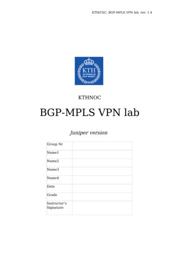
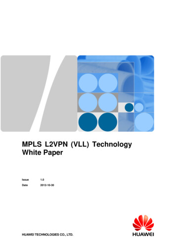
RFC 2547bis: BGP/MPLS VPN FundamentalsRFC 2547bis constrains the distribution of routing information among PE routers by the use ofroute filtering based on BGP extended community attributes (route targets).When PE 2 receives PE 1's route advertisement, it determines if it should install the route toprefix 10.1/16 into VRF Red by performing route filtering based on the BGP extendedcommunity attributes carried with the route. If PE 2 decides to install the route in VRF Red, itthen advertises the route to prefix 10.1/16 to CE 2.LSP EstablishmentIn order to use MPLS to forward VPN traffic across the provider's backbone, LSPs must beestablished between the PE router that learns the route and the PE router that advertises theroute (Figure 3).Figure 3: LSPs Between Site 1 and Site 2Provider NetworkCE 1Site 110.1/16CE 2LSPVRFPE 1VRFLSPM10VRFM20PE 2VRFM40M160Site 410.1/16Site 210.2/16M40Site 310.2/16CE 3CE 4LSPs can be established and maintained across the service provider's network using eitherLabel Distribution Protocol (LDP) or Resource Reservation Protocol (RSVP). The provider uses LDP if it wants to establish a best-effort LSP between two PE routers. Inthis case, the LSP follows the same route as best-effort traffic. The provider uses RSVP if it wants to either assign bandwidth to the LSP or use trafficengineering to select an explicit path for the LSP. RSVP-based LSPs support specific qualityof service (QoS) guarantees and/or specific traffic engineering objectives.To ensure multivendor interoperability, all PE and P routers are required to support LDP at aminimum. If the provider elects to use LDP, a full mesh of best-effort LSPs is established across thebackbone to support PE-to-PE connectivity. If the provider elects to use RSVP, RSVP-based LSPs have a higher priority than LDP-basedLSPs. Both an LDP-based and an RSVP-based LSP exist between a pair of PE routers, theingress label switching router (LSR) selects the RSVP-based LSP instead of the LDP-basedLSP. This model supports the incremental configuration of RSV-based LSPs across theservice provider’s backbone.Copyright 2001, Juniper Networks, Inc.9
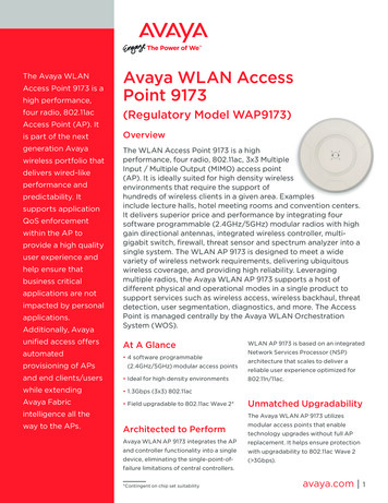
RFC 2547bis: BGP/MPLS VPN FundamentalsNote that there can be a single LSP or several parallel LSPs (perhaps with different QoScapabilities) established between PE routers. Also, a route reflector simply acts as server thatreflects routes from an ingress PE router to egress PE routers. If a provider uses route reflection,it is still required to establish LSPs between PE routers because route reflectors are notnecessarily part of the transit path between PE routers.Data FlowFigure 4 shows the flow of VPN data traffic across the service provider’s backbone from onecustomer site to another customer site. Assume that Host 10.2.3.4 at Site 2 wants tocommunicate with Server 10.1.3.8 at Site 1.Figure 4: Data Flow from Site 2 to Site 1Provider NetworkCE 1Site 1Server10.1.3.8CE 2Site 2Host10.2.3.4M40VRFPE 1VRFLSPM10VRFM160M20PE 2VRFM40Site 410.1/16Site 310.2/16CE 4CE 3Host 10.2.3.4 forwards all data packets for Server 10.1.3.8 to its default gateway. When a packetarrives at CE 2, it performs a longest-match route lookup and forwards the IPv4 packet to PE 2.PE 2 receives the packet, performs a route lookup in VRF Red, and obtains the followinginformation. The MPLS label that was advertised by PE 1 with the route (label 222) The BGP next hop for the route (the loopback address of PE 1) The outgoing subinterface for the LSP from PE 2 to PE 1 The initial MPLS label for the LSP from PE 2 to PE 1User traffic is forwarded from PE 2 to PE 1 using MPLS with a label stack containing twolabels. For this data flow, PE 2 is the ingress LSR for the LSP and PE 1 is the egress LSR for theLSP. Before transmitting a packet, PE 2 pushes the label 222 onto the label stack making it thebottom (or inner) label. This label is originally installed in VRF Red when PE 2 receives PE 1'sIBGP advertisement for the route to 10.1/16. Next, PE 2 pushes the label associated with theLDP or RSVP-based LSP to PE 1 (the route’s BGP next hop) onto the label stack making it thetop (or outer) label.After creating the label stack, PE 2 forwards the MPLS packet on the outgoing interface to thefirst P router along the LSP from PE 2 to PE 1. P routers switch packets across the core of theprovider's backbone network based on the top label. The penultimate router to PE 1 pops thetop label (exposing the bottom or inner label) and forwards the packet to PE 1.10Copyright 2001, Juniper Networks, Inc.
RFC 2547bis: BGP/MPLS VPN FundamentalsWhen PE 1 receives the packet, it pops the label creating a native IPv4 packet. PE 1 uses thebottom label (222) to identify the directly attached CE that is the next hop to 10.1/16. Finally,PE 1 forwards the native IPv4 packet to CE 1, which forwards the packet to Server 10.1.3.8 atSite 1.Benefits of BGP/MPLS VPNsThe major objective of BGP/MPLS VPNs is to simplify network operations for customerswhile allowing the service provider to offer scalable, revenue-generating, value-addedservices. BGP/MPLS VPNs has many benefits, including the following. There are no constraints on the address plan used by each VPN customer. The customer canuse either globally unique or private IP address spaces. From the service provider'sperspective, different customers can have overlapping address spaces. The CE router at each customer site does not directly exchange routing information withother CE routers. Customers do not have to deal with inter-site routing issues becauseinter-site routing issues are the responsibility of the service provider. VPN customers do not have a backbone or a virtual backbone to administer. Thus, customersdo not need management access to PE or P routers. Providers do not have a separate backbone or virtual backbone to administer for eachcustomer VPN. Thus, providers do not require management access to CE routers. The policies that determine whether a specific site is a member of a particular VPN are thepolicies of the customer. The administrative model for RFC 2547bis VPNs allows customerpolicies to be implemented by the provider alone or by the service provider workingtogether with the customer. The VPN can span multiple service providers. While this capability of BGP/MPLS VPNs isimportant, this paper does not describe inter-provider VPN solutions. Without the use of cryptographic techniques, security is equivalent to that supported byexisting Layer 2 (ATM or Frame Relay) backbone networks. Service providers can use a common infrastructure to deliver both VPN and Internetconnectivity services. Flexible and scalable QoS for customer VPN services is supported through the use of theexperimental bits in the MPLS shim header or by the use of traffic engineered LSPs(signaled by RSVP). The RFC 2547bis model is link layer (Layer 2) independent.Copyright 2001, Juniper Networks, Inc.11
RFC 2547bis: BGP/MPLS VPN FundamentalsChallenges and SolutionsRFC 2547bis uses several mechanisms to enhance the scalability of the approach and solvespecific VPN operational issues. These challenges include the following. Supporting overlapping customer address spaces Constraining network connectivity Maintaining updated VPN routing information Conserving backbone bandwidth and PE router packet processing resourcesOverlapping Customer Address SpacesVPN customers often manage their own networks and use the RFC 1918 private address space.If customers do not use globally unique IP addresses, the same 32-bit IPv4 address can be usedto identify different systems in different VPNs. The result can be routing difficulties becauseBGP assumes that each IPv4 address it carries is globally unique. To solve this problem,BGP/MPLS VPNs support a mechanism that converts nonunique IP addresses into globallyunique addresses by combining the use of the VPN-IPv4 address family with the deploymentof Multiprotocol BGP Extensions (MP-BGP).VPN-IPv4 Address FamilyOne challenge posed by overlapping address spaces is that if conventional BGP sees twodifferent routes to the same IPv4 address prefix (where the prefix is assigned to systems indifferent VPNs), BGP treats the prefixes as if they are equivalent and installs only one route. Asa result, the other system is unreachable. Eliminating this problem requires a mechanism thatallows BGP to disambiguate the prefixes so that it is possible to install two completely differentroutes to that address, one for each VPN. RFC 2547bis supports this capability by defining theVPN-IPv4 address family.A VPN-IPv4 address is a 12-byte quantity composed of an 8-byte RD followed by a 4-byte IPv4address prefix. Figure 5 shows the structure of a VPN-IPv4 address.Figure 5: Encoding of Route Distinguishers and IPv4 Addresses8-Byte Route DistinguisherTypeField2-ByteType FieldAdministratorSubfieldAssigned NumberSubfield4-Byte IPv4 AddressIPv4 AddressPrefix6-ByteValue FieldThe 8-byte RD is composed of a 2-byte Type field and a 6-byte Value field. The Type fielddetermines the lengths of the Value field’s two subfields (Administrator and AssignedNumber), as well as the semantics of the Administrator field. Currently, there are two valuesdefined for the Type field: 0 and 1.12Copyright 2001, Juniper Networks, Inc.
RFC 2547bis: BGP/MPLS VPN Fundamentals For Type 0, the Administrator subfield contains 2 bytes and the Assigned Number subfieldcontains 4 bytes. The Administrator subfield holds an autonomous system number (ASN).The use of an ASN from the private ASN space is strongly discouraged. The AssignedNumber subfield holds a value from the numbering space administered by the serviceprovider that offers the VPN service and to which the ASN has been assigned. For Type 1, the Administrator subfield contains 4 bytes and the Assigned Number subfieldcontains 2 bytes. The Administrator subfield holds an IPv4 address. The use of an IPaddress from the private IP address space is strongly discouraged. The Assigned Numbersubfield holds a value from the numbering space administered by the service provider thatoffers the VPN service and to which the ASN has been assigned. A configuration option forType 1 RDs is to use the loopback address of the PE router that originates the route for the4-byte Administrator subfield and to select a number that is local to that PE router for the2-byte Assigned Number subfield.When configuring RDs on PE routers, RFC 2547bis does not require that all the routes within aVPN use the same RD, and in fact, each VRF within a VPN can use its own RD. However, theservice provider must ensure that each RD is globally unique. For this reason, the use of theprivate ASN space or the private IP address space when defining RDs is strongly discouraged.The use of the public ASN space or the public IP address space guarantees that each RD isglobally unique. Globally unique RDs provide a mechanism that allows each service providerto administer its own address space and create globally unique VPN-IPv4 addresses withoutconflicting with the RD assignments made by other service providers. The use of globallyunique RDs supports the following. The creation of distinct routes to a common IPv4 prefix. The creation of multiple, globally unique routes to the same system. The use of policy to decide which packets use which route.Finally, note these few observations to help avoid confusion concerning how VPN-IPv4addresses are used in a BGP/MPLS VPN. VPN-IPv4 addresses are used only within the service provider network. VPN customers are not aware of the use of VPN-IPv4 addresses. VPN-IPv4 addresses are carried only in routing protocols that run across theprovider's backbone. VPN-IPv4 addresses are not carried in the packet headers of VPN data traffic as it crossesthe provider's backbone.Multiprotocol BGP ExtensionsAnother limitation of using conventional BGP4 to support BGP/MPLS VPNs is that it wasoriginally designed to carry routing information only for the IPv4 address family. Realizingthis limitation, the IETF is working to standardize the Multiprotocol Extensions for BGP4. Theseextensions were originally defined in RFC 2283 (February 1998) and later updated in RFC 2858(June 2000). The extensions allow BGP4 to carry routing information for multiple NetworkLayer protocols (IPv6, IPX, VPN-IPv4, etc.). Therefore, to deploy BGP/MPLS VPNs andsupport the distribution of VPN-IPv4 routes, PE routers are required to support the MP-BGPextensions and not just conventional BGP.Before exchanging VPN-IPv4 routing information, RFC 2547bis requires that BGP capabilitiesnegotiation take place to ensure that the BGP peers are both capable of processing theVPN-IPv4 address family. Note that the MP-BGP extensions are backwards compatible so aCopyright 2001, Juniper Networks, Inc.13
RFC 2547bis: BGP/MPLS VPN Fundamentalsrouter that supports these extensions can still interoperate with a router that does not supportthese extensions using conventional BGP4 (however, conventional BGP4 does not support RFC2547bis VPNs).Constraining Network ConnectivityAssuming a routing table does not contain a default route, a basic assumption of IP routing isthat if the route to a specific network is not installed in a router's forwarding table, the networkis unreachable from that router. By constraining the flow of routing information, serviceproviders can efficiently control the flow of customer VPN data traffic. The BGP/MPLS VPNmodel constrains the flow of routing information using two mechanisms. Multiple forwarding tables BGP extended community attributesMultiple Forwarding TablesEach PE router maintains one or more per-site forwarding tables known as VRFs. When a PErouter is configured, each of its VRFs is associated with one or more ports(interfaces/subinterfaces) on the PE router that connects directly to the service provider’scustomers. If a given site contains hosts that are members of multiple VPNs, the VRFassociated with the customer site contains routes for all VPNs of which the site is a member.When receiving an outbound customer data packet from a directly attached CE router, the PErouter performs a route lookup in the VRF that is associated with that
to maintain specific VPN routing information for each customer site. Operational Model Two fundamental traffic flows occur in a BGP/MPLS VPN. A control flow that is used for VPN route distribution and label switched path (LSP) establishment A data flow that is used to forward customer data traffic Sample Network Topology