Transcription
DD2491 p2 2011MPLS/BGP VPNsOlof Hagsand KTH CSC1
Literature Practical BGP: Chapter 10 MPLS repetition,–see for example /ipro111/lectures/MPLS.pdf Reference:–JunOS Cookbook: Chapter 14 and 15–Junos software 10.1 VPNs Configuration Guide–draft-kompella-ppvpn-l2vpn-03.txt, Layer 2 VPN Over Tunnels–RFC 4364 bis (L3VPN)2
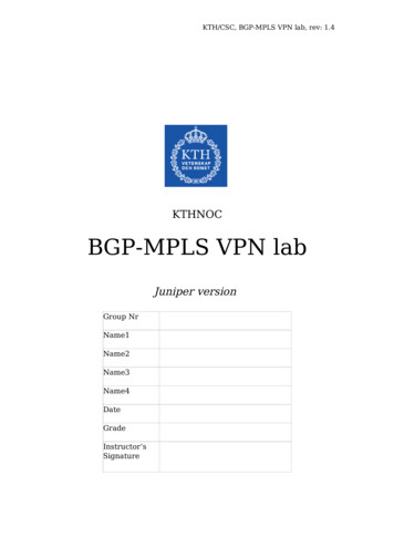
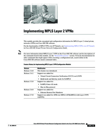
Motivation to VPN Companies and organizations wish to connect their localoffices, collect data in an isolated network, or have personelworking from their home or while travelling. Leased lines are expensive, it makes sense to use IP andthe Internet. The motivation for VPNs is therefore primary economical3
VPN simple architectureConnect hosts to central server/LAN.MainLANIP-networkPoint-to-pointtunnels4
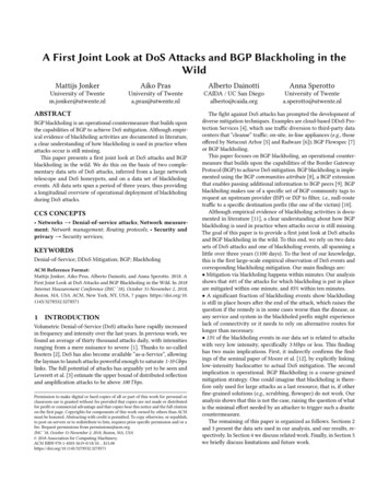
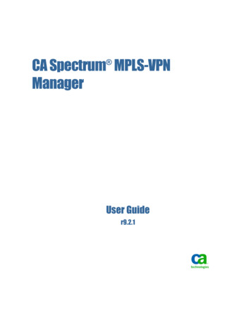
Generic VPN ArchitectureLANLANIP networkConnect several LAN “islands”.LAN5
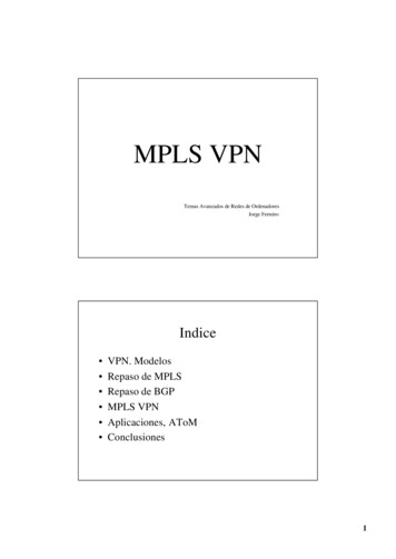
Addressing and Security Public IP networks are public and have only oneaddress domain. You may want to separate your private traffic fromthe global traffic (addressing) You may want to secure your traffic (encryption,authentication) Provider-based VPNs (peer)–You trust your provider–Guarantee resources–Provider adds service – more costly–One provider / set of providers only Customer-based VPNs (overlay)–Do it yourself using IPSEC tunneling–Cheap solution–Best effort–Internet6
Provider-based VPNs using MPLS & BGPThere are several related variants including L2VPN – pseudowires VPLS – dynamic L2VPN L3VPN – RFC 4364These solutions all use multiprotocol BGP, VRF (Virtual Routing andForwarding), relays data with MPLS and have a BGP-free core.In fact, when you have set up your MPLS BGP core network, you canmix these VPNs. You can therefore re-use your infra-structure.If you use RSVP you can also make traffic-engineering.There is no 'security' in Provider-based VPNs.7
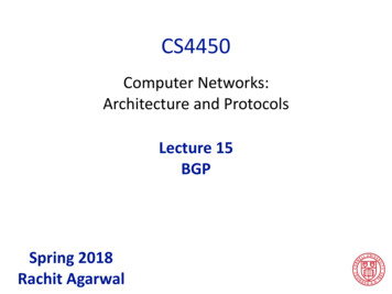
Provider-based VPNs CE - Customer Edge PE - Provider Edge (BGP) P - Provider (no BGP) More than one customer: red andblue More than two sites per customer CE is either router or L2 deviceCECEPEPECEPPCECEPEPE8
L2VPN Pseudowires(customer view)IProvider network acts as a set of wires.Learning and spanning tree can be madeby attaching learning bridges as CE:s tocreate a large LANNote: several circuits per site(You need VLANs)9
L2VPN Pseduowires(customer view)Alternatively, routers can communicateback-to-back over an L2VPN(This is what we do in the lab.)10
VPLS (Customer view)Provider network acts as adistributed switchProvider network performslearning (and spaning-tree)VPLS is dynamicL2VPN is staticNote: only one circuit per site11
L3VPN (Customer view)192.16.100.0/24Provider network acts as a distributed router.Customers must configure routing towards the provider,and LANs are separate IP subnetworks.AS 6510010.2.1.0/2410.1.1.0/2412
L2VPN pseudo-wire Static, multipoint ”overlay” solution Setup point-to-point L2 connections between every site inthe VPN–Pseudo-wires L2 frames are encapsulated using IP and MPLS Requires homogenous link-layers (a wire) but cantransform between some link-layers BGP is used as a signalling protocol to setup VPNconnections between customer sites. RSVP (or LDP) is used to setup the MPLS paths MPLS multistacking is used to keep provider's network freeof customer routing information Encryption by other means, security by trusting theprovider13
L2VPN provider view Access circuits between CE/PE, typically VLAN tagged MPLS LSPs between PEs using RSVP BGP signals L2 circuits between sitesCESite 1CESite 2PEPPPEPEpseudo-wires fullmeshSite 3CE14
Virtual Private LAN Services (VPLS) Dynamic, multipoint ”peer” solution Backbone over IP Interconnects a switched L2 network MPLS is used together with BGP to create ”pseudo-wires”between the LAN islands. The PE:s dynamically establish pseudo-wires–Bridging (learning)–Spanning-Tree The PE:s actively chooses which pseudo-wire to send each frameon MP-BGP is used for distributing mac adress learning Disadvantage (similar to L3VPN)–Provider imports MAC learning tables into network15
VPLS provider view PE:s establish and switches frames on pseudo-wiresSite 1Site 2PEPPPEPEpseudo-wires fullmeshSite 316
CE-PE issues Since CE-PE communication needs to distinguish betweendifferent circuits, it is common to use virtual connections, asCE-PE circuits, such as VLANs. You assign one VLAN per”wire”. There are many link-layers. You need to configure whichencapsulation you use. We use 'ethernet-vlan', but it ispossible to use other encapsulation types and translatebetween them using 'translational cross-connects' VPLS does not need VLANs, since only one connection isrequired, but there are still encapsulation issues17
L2VPN CE-PE configurationCE side:fe-1/0/0 {vlan-tagging;unit 512 {Vlan-id 512; # vid and unit need not matchfamily inet {address 10.10.11.1/30;}}}PE side: no IP address, configure encapsulation vlan-ccc18
Constructing VPNs Before we go into details about configuring L2VPN, youneed to understand some intrinsics about how VPNs areconstructed. You need to understand:–Route distinguisher–VRFs–Route targets These are fundamental in all MPLS/BGP VPNs But these are most easily understood using L3VPN but areused in all VPNs19
L3VPN L3VPN is a ”peer-type” and dynamic VPN using BGP and MPLS It connects IP-subnetworks belonging to the same private network. Each customer may use the same adress space, such as 1918 addresses Each customer site is modelled as a separate AS – customer interiorrouting runs independently at each site An address conversion scheme makes each customer VPN route uniquewithin the provider's network Multiple routing and forwarding tables are supported on each PEseparating different customer routing information BGP is used as a signalling protocol to setup VPN connections betweencustomer sites. RSVP (or LDP) is used to setup the MPLS paths MPLS multistacking is used to keep provider's network free of customerrouting information Disadvantage: Provider imports customer routing tables Encryption by other means, security by trusting the provider20
L3VPN exampleCE192.16.100.0/24192.16.100.0/24CEPECEAS 21
CE to PE routing The local PE learns routes from the local customer CE Static routing, eBGP, RIP, or some other IGP–Customer should be able to decide–Often the customer wants a separate routing protocol forthe CE-PE peering (eg. so OSPF link-state is not propagatedto the provider) The PE router takes the routes and propagates themover the provider network to the remote PE:s The remote PE:s announce the client routes to matchingremote CE sites The remote CE sites can then access the local CE22
CE to PE routing icroutingAS 65100D(You can usedifferent 2423
The Route Distinguisher24
Overlapping addresses:Route Distinguisher How does a provider keep different client prefixes unique?–Eg: Red and blue VPN both have 10.1.1.0/24 A new address class is used, where a unique prefix isprepended to the VPN route–This unique prefix is called a route distinguisher (RD) A new (L3VPN) route is written:– route distinguisher :: IPv4addr / prefixlen 8 bytesRoute Distinguisher4 bytesIPv4 address/site25
Route Distinguisher formatI T Type[Subtype]1 byte1 byteData6-7 bytes The route distinguisher has the same format as the BGPextended community which is 8 bytes. Two variants Type 0 and Type 1 Type 0–Can be better to identify VPNs, or if many AS Type 1 used in the lab–Easier to see the origin of the routes8 bytes4 bytesRoute DistinguisherType 0:2 bytes2 bytes4 bytesType/SubtypeAS#Number2 bytesType 1:IPv4 addressType/Subtype4 bytesIP#IPv4 address2 bytesNumberIPv4 address26
Route distinguisher type 1 Example–192.30.200.3:1::192.16.100.0/24 announced by B You can see where the routes come from And you can see which VPN they belong to (1 blue, 2 red)I192.16.100.0/24192.16.100.0/24HBRD: 192.30.200.3:1RD: 192.30.200.4:2AS 65100DCFRD: 192.30.200.2:2G10.1.1.0/24RD: 192.30.200.1:1AEJ10.1.1.0/2427
Routing table exampleExample: Routing table in a PE router (prefix nexthop)VPN-IPv4 address family (bgp.l3vpn in 0.200.4:2::192.168.100.0/24DIPv4 address 200.428
Operation A CE announces a prefix to a PE–Eg 192.168.100.0/24 to B by H The PE prepends the route distinguisher and announces it to the otherPE:s–Eg 192.30.200.3:1::192.168.100.0/24 The PEs receives the route, strips the route distinguisher andannounces it to the local matching CE–Eg 192.168.100.0/24 to J by E The CE network can reach 192.168.100.0/24 See figure on next slide29
Operation: announcing prefixesI192.16.100.0/24192.16.100.0/24HBRD: 192.30.200.3:1RD: 192.30.200.4:2AS 65100DCFRD: 192.30.200.2:2G10.1.1.0/24RD: 192.30.200.1:1AEJ10.1.1.0/2430
Virtual Routing and Forwarding31
Virtual Routing and Forwarding - VRF A virtual router is a subset of a physical router. A virtual router has its own routing processes, routing tables,forwarding tables and its own interfaces, Typically interfaces of virtual routers are virtual (eg VLANs) The virtual routers are partitioned into several disjoint virtualrouters.Virtual.Physical32
Routing instances in JunOSRouting Instance: mainRIBsRouting Instance: otherRIBsinet.0Routing protocol 3RIBinet.0IPv4 unicast routesinet6.0IPv6 unicast routesinet.1IPv4 multicast forwardingcacheinet.2IPv4 multicast RPF tableinet.3IPv4 routes learnt from MPLSTE path explorationbgp.l3vpnExample:main.inet.0juniper private1 .inet.0Logical routers, VPNs, virtual routers, etc, userouting instances.VPN-IPv4 routesmpls.0MPLS label-switch table33
VRF in a PEExample: A router with two customers instances: VRF1 and VRF2.VRF tableVRF1VRF1VRF mainVRF2VRF mainLocal BGP tableVRF2VRF table34
Using MPLS and RSVPEstablish LSP:s between border routersUse double stacking:––outer tag: LSP PE -- PEinner tag: VPN labelInternal nodes (P-nodes) are only aware of outer tags (PE to PE)With RSVP you set up the outer tag–and can also traffic engineer the LSP:souter:LSP labelinner:VPN labelVRF1VRF1223VRF mainVRF main23VRF21VRF235
Route Target36
VRF Importing and exportingYou export and import routes between the VRF and the global routingdomain by adding or stripping the route-distinguisher using export andimport rules.The rules are expressed using route 0.0/24HexportBRD: 192.30.200.3:1Local BGP 92.168.100.0/24CFERD: 192.30.200.1:1J10.1.1.0/24VRF:37
Route target The purpose of the route target (RT) extended community isto tag the VPN-IPv4 routes with VPN information Rules are then based on route targets The route target has the same format as the routedistinguisher–AS#:number (type 0) – Used in lab–IP#:number (type 1) The route target is used to color the routes–In our example red and blue Example:–RT 65100:100 - blue VPN–RT 65100:3 - red VPN Typically, every VRF has a set of import and export rules Every export rule corresponds to tagging the announced VPNIPv4 route with a route target attribute Every import rule corresponds to matching targets withincoming route target attributes38
Route target example: full mesh Tag the routes when exporting to BGP Import routes matching the target community Full mesh is default policy and can be accomplished in JunOS simply with–set vrf-target target: route target I192.16.100.0/24192.16.100.0/24HBRD: 192.30.200.3:1import: 65100:100export: 65100:100RD: 192.30.200.4:2import: 65100:3export: 65100:3AS 65100DCFRD: 192.30.200.2:2import: 65100:3export: 65100:310.1.1.0/24GRD: 192.30.200.1:1import: 65100:100export: 65100:100AEJ10.1.1.0/2439
Extranet The Extranet is defined between the upper two customer sites–Note that the prefixes have been changed to be unique–And the route targets are unique per PEI192.16.101.0/24192.16.102.0/24HBRD: 192.30.200.3:1import: 65100:1265100:21export: 65100:22AS 65100DCRD: 192.30.200.4:2import: 65100:1165100:22export: 65100:12FRD: 192.30.200.2:2import: 65100:12export: 65100:11AERD: 192.30.200.1:1import: 65100:22export: 65100:2110.1.1.0/2410.1.1.0/24GJ40
Hub-and-spoke VPN All traffic passes via a HUB Filtering / security purposes Note the two peerings at AI10.1.3.0/2410.1.4.0/24HBRD: 192.30.200.3:1import: 65100:200export: 65100:100AS 65100DRD: 192.30.200.4:2import: 65100:200export: 65100:100CRD: 192.30.200.2:2export: 65100:200FAKERD: 192.30.200.1:1import: 65100:200export: 65100:100import: 65100:100Filtering10.1.1.0/24iBGPGJ41
L2VPN and L3VPN lab1)Build an MPLS backbone2)Configure L2VPN3)Configure L3VPN42
MPLS backboneBackboneRTC1RTB3RTB4RTC2RTB1RTB2RTC3RTC443
L2VPN setup10.1.3.0/30VLANID: 514Provider Edge (PE)10.1.2.0/3010.1.1.0/30VLANID: 512 VLANID: 513.1 .2.1 .1.2.2Customer Edge (CE)RTD2RTA2RTE244
L2VPN configuration examplerouting-instances {L2VPN {description "experimental L2VPN";instance-type l2vpn;interface fe-0/0/0.512;route-distinguisher 192.168.4.2:10;vrf-target target:65000:10;protocols {l2vpn {encapsulation-type ethernet-vlan;no-control-word;site RED {site-identifier 1;interface fe-0/0/0.512 {remote-site-id 2;}}}}}}45
L2VPN Junos show commands show show show show show showl2vpn connections [extensive]route protocol l2vpnroute protocol bgpmpls lspbgp summaryroute193.10.255.5:10:1:1/96*[L2VPN/170/ 101] 02:45:38, metric2 1Indirect193.10.255.6:10:2:1/96*[BGP/170] 01:36:41, localpref 100, from 193.10.255.6AS path: I via so 0/1/0.0, label switched path btoc193.10.255.13:10:3:1/96*[BGP/170] 01:38:11, localpref 100, from 193.10.255.13AS path: I via so 0/1/0.0, label switched path btod46
Configuring L2VPN Setup the backbone: ISIS, MPLS, RSVP, IBGP–Enable 'l2vpn signaling' as bgp protocol family Setup CE-PE circuits (VLANs)–Use Ethernet interface with units 0–Use VIDs 512 (or use 'flexible' services)–Set RFC1918 addresses on the VLANs Setup an l2vpn routing instance: Set route distinguisher– PE loopback : vpnid Setup sites and setup LSPs by connecting remote sites–Bind vlans to remote sites using vlanids Setup encapsulation–'ethernet-vlan' Set no-control-word (used for other link-layers) Setup vpn import/export rules–use vrf-target L2VPN routes:– RD : site :1/96–Example: 193.10.255.5:10:3:1/9647
VPLS configuration examplerouting-instances {VPLS {instance-type vpls;interface ge-3/0/1.512;route-distinguisher 192.168.4.2:10;vrf-target target:65000:10;protocols {vpls {no-tunnel-services;site RTA {site-identifier 1;}}}}}48
L3VPN setupProvider Edge ustomer Edge (CE)RTD3RTA3RTE349
L3VPN configuration exampleprotocols {bgp {local-address 192.30.200.3;group internal {type internal;family inet-vpn unicast;neighbor 192.30.200.1;}}}routing-instances {VRF1 BLUE {instance-type vrf;interface fe-0/0/0.0;route-distinguisher 192.30.200.3:1;vrf-target target:65100:100;vrf-table-label;protocols {bgp {group siteB {type external;peer-as 1;neighbor 192.16.100.1; # H}}}}50
LAB overviewBackboneRTB3RTB4RTC1RTC2RTC2RTC2RTE4L3VPN #4L1VPN #1RTE2 RTE3L3VPN #3RTE1L2VPN #2RTA4L3VPN #4RTA2 RTA3L3VPN #3RTA1RTB2L2VPN #2L3VPN #3L2VPN #2L2VPN #1RTD4L2VPN #1RTD2 RTD3L3VPN #4RTD1RTB151
11/lectures/MPLS.pdf Reference: . -Junos software 10.1 VPNs Configuration Guide -draft-kompella-ppvpn-l2vpn-03.txt, Layer 2 VPN Over Tunnels -RFC 4364 bis (L3VPN) 3 Motivation to VPN Companies and organizations wish to connect their local . L3VPN is a "peer-type" and dynamic VPN using BGP and MPLS