Transcription
08/01/2015SkyGuardTWX “Vision-Pro Plus” 978mhz UAT/ES ADS-BTransceiverInstallation and Operation Manual(for use when remote installing in Experimental or LSA Aircraft)Part Number: UAT1000-EXFCC ID: R83UAT1000Business Address:SkyGuardTWX, LLC208 Sunday DriveBurnet, Texas 87611Phone Number:512-784-7766Email Address:Don@SkyGuardTWX.comWEB Site:www.SkyGuardTWX.comDocument HistoryRevision1.0Date03/01/2015Initial Release1.108/01/2015Updated specs. for new GPS1Comments
08/01/2015Table of 5.35.45.55.66.07.08.08.18.28.38.49.0System Description . 04Reference Documents . 05Regulatory Compliance . 06TSO . 06TSO Authorization . 06FCC Grant of Equipment Authorization . 06Installation Limitations . 07Surveillance Services . 07Flight Manual Supplement . 08Other Considerations . 08Equipment Installation . 09Package Contents . 09Overall Specifications . 10System Interfaces . 11Antenna Requirements/Installation . 11Temperature/Air Flow Requirements . 12Installation Mounting . 12Electrical Connections . 15Power Connections . 16Display Connections . 16Transponder Connections . 17Annunciator Light Connections . 17Initial Configuration Programming . 18Post Installation Verification . 19Transceiver DC Power Verification . 19GPS Verification . 20Pressure Altitude Encoder Verification . 20UAT Transmitter Verification . 20UAT Receiver Verification . 20Annunciator Light Verification . 20Weight and Balance . 21Inflight Operation . 21Maintenance . 22Altitude Source . 22Calibration . 22Cleaning . 22Tune-Up . 22Warnings and Disclaimers . 232
08/01/20153
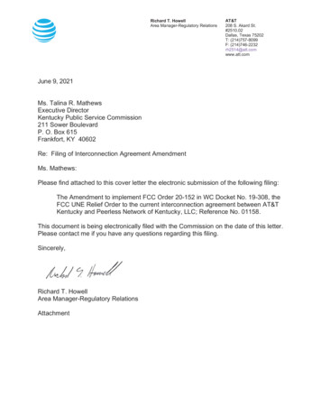
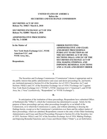
08/01/20151.0System DescriptionThis Transceiver is a fully integrated 978mhz UAT ADS-B radio transceiveralong with a WAAS GPS (TSO-C199 certified) and WiFi transmitter. The main unitalso contains circuitry to interface with a panel mounted display and a Mode A/C/Stransponder. Additionally, there are 2 RF receiver channels (one at 978mhz and one at1090mhz) that allow receipt of FIS-B and TIS-B messages from ADS-B ground stationtowers as well as ADS-B traffic messages from direct air-to-air aircraft. The non-TSO’dversion of this transceiver (P/N: UAT1000-EX) contains an internal GPS position sourcethat will “meet the performance requirements of TSO-C199 and TSO-C154c” wheninstalled in an Experimental or LSA aircraft. This new FAA rule change was enacted onFebruary 9, 2015 by changes to: 14 CFR 91.225 section b.1.ii. When installing in anLSA, a letter of authorization is required from the LSA manufacturer.The unit is intended to be permanently installed and connected to aircraft power througha fused/switched dedicated power connection to the aircraft avionics power bus.The unit will operate utilizing a DC power source ranging from 10 volts to 30 voltswith a minimum of 3 amps of current.There are 6 antennas connections (1- 978mhz for UAT transmitter, 1- 978mhz for UATreceiver, 1- 1090mhz for 1090ES receiver, 1- for GPS antenna, 1 – for WiFi transmitter,and 1- for Interrogator antenna). All antennas (except GPS, WiFi and Interrogator) areintended to be mounted externally on the belly of the aircraft. The Transceiver installerwill be responsible for purchasing the required external antennas and RF coax cables.See Figure 1 for system block diagram:Figure 1: System Block Diagram4
08/01/2015Reference Documents1.1RTCA/DO-282BRTCA Document. Minimum OperationalPerformance Standards for Universal AccessTransceiver (UAT) Automatic DependentSurveillance – Broadcast (ADS-B)RTCA/DO-160FRTCA Document. Environmental Conditions andTest Procedures for Airborne Equipment.TSO-C154cTechnical Standard Order Universal AccessTransceiver (UAT) Automatic DependentSurveillance-Broadcast (ADS-B) EquipmentOperating on Frequency of 978MHzTSO-C145cTechnical Standard Order for AirborneNavigation Sensors Using The Global PositioningSystem (GPS) Augmented By The Satellite BasedAugmentation System (SBAS)AC 20-165AAirworthiness Approval of Automatic DependentSurveillance-Broadcast (ADS-B) Out SystemsAC 20-138BAirworthiness Approval of Global NavigationSatellite Systems (GNSS) EquipmentTSO-C190Technical Standard Order for Active AirborneGlobal Navigation Satellite System (GNSS)AntennaTSO-C199Technical Standard Order for Light AircraftSurveillance Equipment (LASE)91.225Equipment, Instrument, and CertificateRequirements91.227ADS-B Equipment Performance Requirements5
08/01/20151.2Regulatory Compliance1.2.1TSOSkyGuardTWXTransceiver Part Numbers:UAT1000-EXUniversal Access Transceiver(UAT) Automatic DependentSurveillance-Broadcast (ADSB) Equipment Operating onFrequency of 978MHz. Unit“meets the performancerequirements of TSO-C154c”when installed in Experimentalor LSA aircraft per FAA rulechange enacted on February areRTCA/DO178BHardwareRTCA/DO-254EnvironmentalUAT TransceiverTSO-C154cClass B1SRTCA/DO-282BLevel CLevel 1.2.3FCC Grant of Equipment AuthorizationThis equipment has been issued an FCC Grant of Equipment Authorization.The FCC ID is: R83UAT1000 and is also marked on the equipment nameplate.6RTCA/DO-160F
08/01/20152.0Installation LimitationsThe conditions and tests required for TSO approval of this article are minimum performancestandards. Those installing this article, on or in an Experimental or LSA type class of aircraft,must determine that the aircraft installation conditions are within the TSO standards. TSOarticles must have separate approval for installation in an aircraft. The article may beinstalled only according to 14 CFR part 43 or the applicable airworthiness requirements.The article must be installed according to AC 20-165 applicable airworthiness requirements.A “letter of conformance” from SkyGuardTWX LLC stating that the unit “meets theperformance requirements of TSO-C154c” is required.The UAT Receiver Antenna MUST be installed no less than 4 feet from any L-Band(Transponder, TCAS, TAS) antenna.The UAT Receiver Antenna MUST be installed no less than 4 feet from any DistanceMeasuring Equipment (DME) antenna.The UAT Receiver Antenna MUST be installed no less than 2 feet from the UAT Transmitterantenna.The UAT Transmitter Antenna MUST be installed no less than 3 feet from any L-Band(Transponder, TCAS, TAS) antenna.The UAT Transmitter Antenna MUST be installed no less than 4 feet from any DistanceMeasuring Equipment (DME) antenna.The UAT Transmitter Antenna MUST be installed no less than 4 feet from any Comm. RadioAntenna.The 1090mhz Receiver Antenna MUST be installed no less than 2 feet from the UATTransmitter antenna and no less than 3 feet from any L-Band (Transponder, TCAS, TAS)antenna.The Transponder interrogator antenna can be no closer than 4 feet from your Mode CTransponder antenna.Failure to adhere to these critical installation notes could result in failure of the Transceiverand/or other radio equipment in said aircraft and will void your warranty.2.1ATC Surveillance ServicesAir Traffic Control (ATC) Surveillance Services are accomplished through the UAT data linktechnology. To use these services there must be a “single point of entry” for the ATCassigned squawk code. A single point of entry allows the squawk code to be transmitted byboth the onboard Transponder as well as the SkyGuardTWX UAT Transceiver. TheSkyGuardTWX UAT Transceiver supports the following control panel interfaces foracquiring an ATC assigned squawk code:Compatible Transponders may be configured to act as a control panel for the SkyGuardTWX ADS-BUAT Transceiver. These transponders are: GTX 320, GTX 327, GTX 330, King KT76, Narco,Tera. Other Transponders may also be used but have not been tested with the SkyGuardTWXTransceiver.7
08/01/20152.2Flight Manual SupplementThe Aircraft Flight Manual Supplement for installations of the SkyGuardTWX UATTransceiver must include the following operational limitations:When the transceiver is set to Standby or OFF the transceiver stops transmitting ADS-B messages after atime period of 2 seconds. The ADS-B ground stations only transmit Traffic Information Services –Broadcast (TIS-B) and ADS-Rebroadcast (ADS-R) messages to participating aircraft. Participating aircraftare identified as aircraft transmitting ADS-B messages. When the transceiver is set to Standby or OFF theADS-B transceiver no longer receives TIS-B and ADS-R messages from the ADS-B ground stations thatwere specifically generated for a unique transmitting aircraft because that aircraft is not participating in theADS-B surveillance system.For all installations that include a traffic display, the following must be included in the FlightManual Supplement:“Caution: Traffic shown on the display may or may not have traffic alerting available.”For all installations that do not contain an aircraft Transponder, the following must beincluded in the Flight Manual Supplement:“ATC assigned squawk codes may be entered into the ADS-B radio manually. This isaccomplished using a dedicated control head or using a software app. capable ofcommunicating with the ADS-B radio. Once such app. for the Apple iPad/iPhone isSkyGuardTWX which is available for free download from the Apple Store.”The Vision-Pro Plus transceivers have a squawk detector circuit to retrieve the Mode CTransponder squawk code and pressure altitude code.2.3Other ConsiderationsThe SkyGuardTWX Transceiver is used as an aid to visual acquisition of traffic and weatherand it is to be used only for pilot and crew situational awareness.The SkyGuardTWX Transceiver does not relieve the flight crew of seeing and avoidingtraffic, obstacles, and weather. Installation of the SkyGuardTWX Transceiver does notrelieve the pilot of consulting approved data sources prior to and during each flight.The SkyGuardTWX Transceiver is not a collision avoidance device. Any deviation fromATC clearance, given cockpit information derived from the SkyGuardTWX Transceiver,must be approved by ATC.The SkyGuardTWX Transceiver is a Universal Access Transceiver (UAT) that interfaceswith MFDs, CDTIs and/or EFISs to display ADS-B, ADS-R, TIS-B and FIS-B products. It isthe responsibility of the display manufacturer to render or not render these products.The SkyGuardTWX Transceiver receives ADS-R, TIS-B and FIS-B products from ADS-Bground based radio stations. The content, or lack of content, in the product offerings is theresponsibility of the FAA.8
08/01/20153.0Equipment Installation3.1Package ContentsSkyGuardTWX Transceiver ADS-B radio unitDC Power connector plugInterrogator antenna1090 mhz receiver antenna (for use when no belly mounted antenna is installed)WiFi antennaGPS antennaMounting bracketInstallation manual(no external antennas are included)3.2SpecificationsThis section includes the physical, environmental, electrical, and performance specifications forthe SkyGuardTWX UAT ADS-B 920 inches (includes mounting bracket)4.600 inches (includes mounting bracket)9.300 inches (includes mounted antennas)1.4 lbs (excluding antenna cables and power cable)Environmental:The SkyGuardTWX ADS-B Transceiver is designed and tested to meet the categories as defined in RTCA/DO160F:Operating temperature:Storage temperature:Temperature variation:Humidity:Maximum continuous altitude:External Cooling:-20 C to 55 C-55 C to 85 C5 C per minute95% at 50 C25,000 feetNot requiredElectrical:Voltage:Input Current (5W nominal):910-30VDCSteady State: 0.3A @ 13VDC, 0.25A @ 28VDCTransmit Peak: 2.5A @ 13VDC, 2.4A @28VDC
08/01/2015UAT Performance:TSO Compliance:Regulatory:Frequency:Tolerance:Data Rate:Receiver Sensitivity:Transmit Power:Equipment Class:TSO-C154cRTCA/DO-282B978MHz /- 20ppm1.04167 MbpsExceeds 90%MSR@-91dBm30W nominalB1S (single bottom UAT antenna)TSO-C199 Compliant Internal GPS/WAAS Receiver Performance(P/N: UAT1000-EX)Number of channels:Frequency:Sensitivity (Tracking Mode):Sensitivity (Reacquisition Mode):TTFF Hot (valid almanac, position, time andephemeris):TTFF Warm (valid almanac, position and time):TTFF Cold (valid almanac):Reacquisition ( 10seconds obstruction):Position Update Interval:Velocity:Datum:12 GPS - 3 SBAS (WAAS, RAIM)1575.42MHz L1-162dBm-160dBm15 seconds (average) 30 seconds (average) 45 seconds (average)0.1seconds (average)4 Hz1,000 m/s maximum @ 60,000 ft. MSLWGS-84Avionics Interfaces:(DB 9 I/O Connector)Annunciator Output:Capable of driving a 5 VDC LED lampTransponder Squawk Code input:Wireless from aircraft Mode A/C/S TransponderPressure Altitude Encoder Input:Wireless from aircraft Mode C/S TransponderDisplay/Control Input/Output (optional):RS232 asynchronous serial at 460,800 Baud10
08/01/20153.3System InterfacesThe SkyGuardTWX UAT Transceiver must be configured so that it will acquire aTransponder squawk code and pressure altitude code from the “Ownship” Transponder.This is accomplished with the automatic squawk detector circuit contained in the Vision-ProPlus Transceiver. Optionally, the Transceiver may be configured to output to a fixed paneldisplay or a handheld tablet display to depict ADS-B, ADS-R, TIS-B traffic and FIS-Bweather messages information. NOTE: Capability NOT in current firmware.3.4Antenna Requirements/InstallationIf the SkyGuardTWX Transceiver (P/N: UAT1000-EX) is configured to use the internal noncertified GPS as its position source. The provided GPS antenna must be attached to the GPSantenna port on the transceiver. The antenna performance is critical to the operation of theGPS/WAAS receiver.The performance of the GPS/WAAS Receiver is affected by the gain, noise figure,impedance, and frequency selectivity characteristics of the antenna and the placement of thisantenna within the aircraft. The transceiver should be used only with the provided antennaand cable. Use of other antennas and cables may not meet all of the performancecharacteristics specified.The SkyGuardTWX UAT Transceiver (P/N: UAT1000-EX) utilizes an active GPS antennawhich means that the antenna includes a low noise amplifier. The power for the low noiseamplifier is provided from the GPS receiver via the GPS antenna cable.The GPS antenna must be installed inside the aircraft with a clear view of the upward sky.At least 6 satellites must be acquired in order to maintain a valid GPS location fix.The SkyGuardTWX Transceiver requires two 978mhz UAT antennas meeting the followingspecification: standard 50Ω vertically polarized antenna with a VSWR 1.7:1 at 978MHz.These UAT antennas must be installed on the bottom side of the aircraft fuselage.The SkyGuardTWX Transceiver requires one 1090mhz antenna meeting the followingspecification: standard 50Ω vertically polarized antenna with a VSWR 1.7:1 at 1090MHz.This 1090ES antenna can be installed on the bottom side of the aircraft fuselage.If not installed, use the 6” black monopole antenna provided with the kit.A list of recommended 978mhz and 1090mhz antennas for use with this transceiver arebelow:Delta POP “Wing” (978mhz – experimental aircraft)Rami AV-74 “Wing” (978mhz – certified aircraft)Rami AV-22 “Ball and Stick” (1090mhz – certified aircraft)Operating the SkyGuardTWX Transceiver without RF terminations on the UAT TransmitterAntenna port can result in equipment damage. Operate the transceiver only with the UATTransmitter antenna port terminated with a VSWR ratio of 2.0:1 or less attached to thisantenna port.11
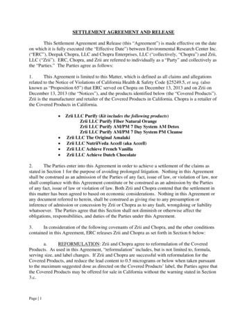
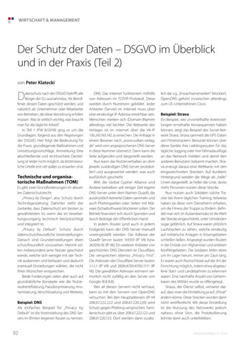
08/01/20153.5Temperature/Air Flow RequirementsThe SkyGuardTWX Transceiver meets all DO-282B requirements without external cooling.However, as with all electronic equipment, lower operating temperatures will extendequipment life. It is not recommended to use “outside aircraft” forced air to cool the unit.Instead it is recommended that the unit be mounted in a location that contains an electricforced air fan to assist in cooling the equipment. If this is not possible, then install the unit inan area where the ambient air temperature does not exceed 40C. Do not mount thetransceiver where it will receive direct sunlight as the radiated heat induced from the sunlightmay cause the unit to exceed its maximum temperature rating.3.6Installation MountingThe SkyGuardTWX Transceiver should be mounted to a rigid surface able to withstandinertial forces imposed by the 1.4 pound unit. The transceiver may be mounted using 4bolts/nuts and 8 washers where the washers are placed on both the bolt side and nut side.Refer to the bolt/nut fastener manufacturer for torque guidelines. The SkyGuardTWXTransceiver should be connected to the airframe ground via the mounting bolts with braidedstrap to airframe ground.Figure 2 below describes the Transceiver mounting bracket and attachment bolt pattern:Figure 2: Transceiver Mounting Bracket12
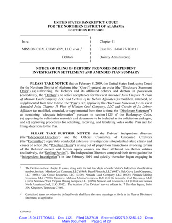
08/01/2015Figure 3: External Antenna ConnectionsFigure 4: System I/F and Power Connections13
08/01/2015The external GPS antenna should not be mounted close to VHF COM transmitter antenna,and other antennas emitting high power. Special care should be taken to ensure that the GPSantenna is not mounted in close proximity to antennas that may emit harmonic interference atthe L1 frequency of 1575.42 MHz.The external GPS antenna placement guidelines can be found in AC 20-138A section 16.For best performance, select an antenna location with an unobstructed view of the sky abovethe aircraft when in level flight.The external UAT Receiver Antenna MUST be installed no less than 4 feet from any L-Band(Transponder, TCAS, TAS) antenna.The external UAT Receiver Antenna MUST be installed no less than 4 feet from anyDistance Measuring Equipment (DME) antenna.The external UAT Receiver Antenna MUST be installed no less than 2 feet from the UATTransmitter antenna.The UAT Transmitter Antenna MUST be installed no less than 3 feet from any L-Band(Transponder, TCAS, TAS) antenna.The external UAT Transmitter Antenna MUST be installed no less than 4 feet from anyDistance Measuring Equipment (DME) antenna.The external UAT Transmitter Antenna MUST be installed no less than 4 feet from anyComm. Radio Antenna.The external UAT Transmitter Antenna MUST be installed no less than 3 feet from anyTransponder Radio Antenna.The 1090mhz Receiver Antenna MUST be installed no less than 2 feet from the UATTransmitter antenna and no less than 3 feet from any L-Band (Transponder, TCAS, TAS)antenna.The Transponder interrogator antenna can be no closer than 4 feet from your Mode CTransponder antenna.Failure to adhere to these critical installation notes could result in failure of the Transceiverand/or other radio equipment in said aircraft and will void your warranty.RG-400 coaxial cable is required for the two UAT antennas and the 1090mhz receiverantenna. UAT Antenna cable loss should not exceed 2 dB. A 9 foot RG400 coaxial cablecomposed of RG400 1.5 dB loss. Limit the RG400 cables length to a maximum of 10 feet.14
08/01/20153.7Electrical ConnectionsAfter the DB9 cable assembly is constructed to interface with the panel annunciator light andoptionally a panel mounted display and installed on the SkyGuardTWX Transceiver, routethe wire bundle as appropriate. Use cable ties to secure the cable assembly. Any ringterminals that are affixed to any cable shields of the cable assembly should be attached to thetransceiver ground via one of the 4 mounting screws that secure the unit mounting bracket.The transceiver should be installed in accordance with Reference to AC 43.13-1B Chapter11. Refer to: The cable assembly should not be exposed to wire chafing The cable assembly should not be located near the fuel lines. The cable assembly should not be located near high electrical capacity lines. The cable assembly should not be routed near high energy sources. The cable assembly should not be located near the flight control cables. Isolate the cable assembly from the engine. Install cable assembly in a protected area of the aircraft. Grounding pigtails should not exceed more than 4 inches in length. Use 24 AWG or larger for all wiring except for power. Use 18 AWG or larger for power wiring.A 9 pin D-Sub connector (female) interfaces to external equipment. This connector can befound at the rear of the SkyGuardTWX Transceiver unit. The following list shows thedefinition of the individual pins in this connector.Pin 1Pin 2Pin 3Pin 4Pin 5Pin 6Pin 7Pin 8Pin 9-15for future useExternal Display RS232 Serial Output @ 460,800 BaudExternal Display RS232 Serial Input @ 460,800 Baudfor future useGroundfor future usefor future usefor future useExternal Annunciator Light (LED) ( 5 VDC)
08/01/20153.71Power ConnectionThe Transceiver power connector to interface with aircraft power can be found at the rear endof the SkyGuardTWX Transceiver unit. A specific “locking power plug” is included as partof the installation kit. The center conductor of this power plug should be connected to the VDC power source for the unit. The shield conductor of this power plug should beconnected to the Ground power return for the unit. The transceiver primary power source assupplied by the aircraft avionics power bus should have an inline circuit breaker rated at 5amps and an on/off switch. The installed ON/OFF switch should be labeled:“ADS-B Transceiver ON/OFF”.The unit will operate utilizing a DC power source ranging from 10 volts to 30 voltswith a minimum of 3 amps of current. The power supply cable going from the inlinecircuit break to the SkyGuardTWX Transceiver should be composed of 18 gauge orlarger stranded wire.3.72Display Connection (Optional)The SkyGuardTWX Transceiver supports interfacing with a panel mounted display fordepiction of GPS position data, ADS-B Weather, and Traffic information. If a fixeddisplay is intended to be used for this installation, then there are three PCB jumpers thatmust be configured inside the transceiver housing. Contact SkyGuardTWX for furtherinstructions on how to set these jumpers.The desired panel display must support the GDL90 software protocol running over anRS232 Serial Data Link. This data link must support the 460,800 serial baud rate.Connect the panel display RS232 input line to DB9-pin 2. Connect the panel displayRS232 output line to DB9-pin 3. Connect the panel display Ground to DB9-pin 5.Contact the display manufacturer to insure it supports the above requirements prior toperforming the install. GRT panel mounted displays have been verified to work withthis interface connection using an RS232 to USB converter cable.16
08/01/20153.73Transponder Hardwired Connection (optional)The SkyGuardTWX Transceiver supports interfacing with a panel mounted Transponderfor acquisition of transponder squawk codes and pressure altitude codes. Normally thiswould not be required as the SkyGuardTWX Transceiver contains a circuit that canwirelessly listen to the Transponder to collect the squawk code and pressure altitudecode. If this is required, then a special version of Transceiver firmware will be requiredas well as additional internal jumper settings. Contact SkyGuardTWX for furtherdetails.3.74Annunciator Light ConnectionThe SkyGuardTWX Transceiver supports control of a panel mounted Annunciator light.The light should be of an LED type and of color GREEN. The light should support adrive current of up to 25 milliamps at 5 VDC. The drive connection of this light shouldbe connected to DB9 pin-9. The ground return connection of this light should beconnected to DB9-5.This light will initially come ON and begin blinking whenever the Transceiver is firstpowered on. Then once the transceiver has acquired a valid GPS position fix and thetransmitter is determined to be ON and transmitting a valid ADS-B message, the lightwill go to a solid ON state. If for any reason the transmitter is found to be at fault andnot transmitting, or the GPS position fix is found to be invalid, this light will blinkON/OFF. If your Mode C Transponder is set to non-altitude reporting mode, the lightwill blink ON/OFF.A label showing “ADS-B Transmitter ON” should be affixed to the panel adjacent to theannunciator light.17
08/01/20154.0Initial Programming of Transceiver Configuration ParametersAfter installation of the SkyGuardTWX UAT Transceiver with power and all antennaconnections in place, the transceiver must be configured, prior to your first flight, tocontain the following required parameters specific to the installed aircraft:-N-number of installed aircraftICAO code of installed aircraftDefault ATC Squawk codeThere are several options for configuring these parameters into the non-volatile memoryof the transceiver. The primary method is to use a wireless tablet display withappropriate software which allows communication with the transceiver. There areseveral flight apps. available for IOS or Android tables that support configuration andupdate of the SkyGuardTWX Transceivers. There is also a dedicated programmingapplication for the Apple iPad/iPhone which is available for download from the AppleApp. Store under the name “SkyGuardTWX”.------If using an iPad/iPhone to perform this initial configuration, first download theSkyGuardTWX app.Make sure you SkyGuardTWX Transceiver is powered on and has a valid GPSposition fix.Then, on your Apple device, go into “Settings” and turn ON Airplane mode.While in “Settings”, turn on WiFi and after a brief search, a WiFi hot spot willappear showing “SkyGuardTWXxx” where “xx” is a numeric value specific toyour ADS-B Transceiver.Select this WiFi hot spot by tapping on it’s name.Wait for approximately 10 seconds for the Apple device to establish a connectionto the ADS-B transceiver over WiFi. If a connection is not established, turn offyour WiFi on the Apple device and power cycle the transceiver. Then try again.Once connected, close “Settings” on the Apple device.Select the SkyGuardTWX app. on your iPad/iPhone or any other Flight App. thatsupports the SkyGuardTWX Vision-Pro UAT/ES Transceiver on the Appledevice.On the SkyGuardTWX app., you will see a main screen display showing Nnumber, ICAO, squawk code, and several other parameters. There are factorydefault values already stored into your Transceivers memory. The transmitter willnot come on until you enter your specific aircraft values for these parameters.Next, enter the N-number of your installed aircraft.Enter the ICAO number for your aircraft. This number can be found by doing anN-number inquiry search on the www.faa.gov web site. Once you put in your nnumber, the site will display a table of parameters about your specific aircraft.The ICAO number is on the right side of this table and is a 6 character alphanumeric number stated as “Mode S Code (base 15/hex).Enter a default squawk code of “1200” by using the number keys on the display.There are several other parameters that can be set/modified such as the following
RTCA/DO-178B Hardware RTCA/DO-254 Environmental UAT Transceiver TSO-C154c Class B1S RTCA/DO-282B Level C Level C RTCA/DO-160F GPS/WAAS Receiver TSO-C199 RTCA/DO-160F 1.2.3 FCC Grant of Equipment Authorization This equipment has been issued an FCC Grant of Equipment Authorization. .