Transcription
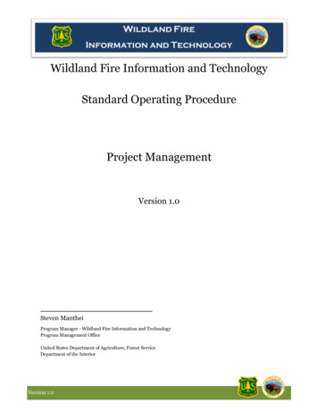
Standard Operating Procedure of Vibrating Sample Magnetometer(VersaLab 3 Tesla Cryogen-free VSM)Part I: Taking VSM MeasurementsI System Preparation for VSM InstallationTo prepare the System for installation of the VSM option, you will use the MultiVu application to warmthe sample chamber to 300K, set the magnetic field to zero (0) Oe, and vent the sample chamber. Then,you will remove any sample puck or option that is currently installed in the chamber. When you do this,be sure to remove the standard centering ring from the chamber opening.(1) Set the system temperature to 300 K:(2) Set the field to zero (0) Oe.(3) Vent the sample chamber.(4) Remove any sample puck or option that is installed in the sample chamber.(5) Remove the standard centering ring (or any other hardware that is present) from the top flange of thesystem.II Install the Coilset PuckThe coilset puck contains the VSM detection coils and a thermometer for monitoring the sampletemperature. You will insert the coilset puck into the sample chamber by using the standard puckinsertion tool. Install the puck before you insert the sample tube.1. On the system, verify that all items have been removed from the sample-chamber opening, includingthe standard centering ring.2. Locate the serial number of the detection coilset puck (4096-204 or 4096-600), as shown in Figure 1-A.This serial number will be used to identify the calibration data for the coilset in a later step.3. Insert the coilset into the sample chamber by using the puck-insertion tool, as illustrated in Figure 1-B.1
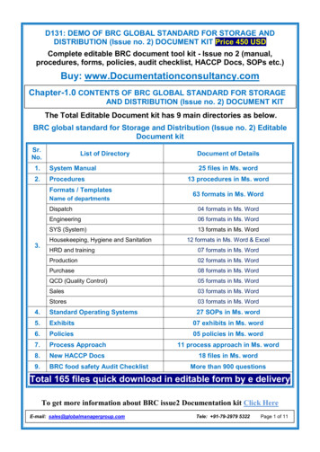
Fig. 1a Coilset puck (4096-204 or 4096-600), with arrows to coilset serial number and to mounting ringfor attaching the puck-insertion tool.Fig. 1b Installing the VSM coilset puck with the puck-insertion tool.III Insert the Sample Tube1. Verify that the standard centering ring has been removed from the top of the system. (A VSMspecific centering-ring assembly has been integrated into the VSM sample-tube assembly.)Important: You cannot use a standard centering ring between the VSM linear motor transport and thesample chamber. As a safety mechanism, the VSM system cannot be installed on the system without theVSM-specific components, such as the VSM sample-tube assembly with its integrated centering-ring andstabilizer post.2. Examine the O-ring on the sample-tube centering ring for dust or dirt. If it is dirty, clean it and lightlygrease it with silicone vacuum grease.3.Using Figure 2-5 as a guide, carefully lower the sample tube assembly into the sample chamber untilthe VSM centering ring seats onto the top flange.Fig. 2a: VSM sample-tube assembly (4096-301 is shown forexample)Fig. 2b: Inserting the VSM sample tube into the sample chamberIV: Mount the VSM Linear Motor Transport2
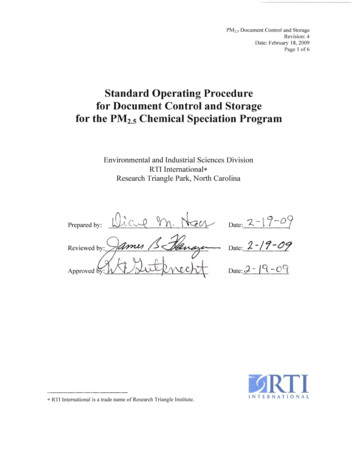
Figure 3: Front and rear views of the VSM linear motor transport (4096-400). The rear view (right)1. Remove the VSM linear motor transport from the stand, keeping it upright. For example, you cansupport the weight of the linear motor transport by gripping it with one hand on the top tube and the otherhand on the extender tube flange.2. Place the VSM linear motor transport onto the top flange of the system by orienting the electricalconnector to the rear of the cryostat. The linear motor transport should slide over the stabilizer post at thetop of the VSM sample-tube assembly.3. Verify that the integrated VSM centering ring is sandwiched snugly between the top flange and thelinear motor transport.4. Attach the flange clamp to the flange. Always use the flange clamp to hold the linear motor transportonto the stabilizer post.3
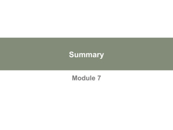
Figure 4: Install the VSM linear motor transport on the top flangeV: Configure the VSM SystemThe serial number of the detection coilset puck identifies the calibration file that is used to calibrate thecoilset. You must verify that the serial number on the puck, You will use the Configure VSM Systemdialogs to specify the puck serial number and test the VSM hardware.1. Locate the puck serial number.2. Click on the Configure VSM System button.3. The Configure VSM System dialog will open. Note the text box where you will enter the serial numberof the standard VSM calibration file.4. Verify that the number in the text box matches the serial number of your detection coilset puck. If nonumber is displayed (as above), enter the serial number of your detection coilset puck in the text box.4
5. Click on the Next button at the bottom of the dialog box. The Configure VSM System dialog willopen, showing the results of system tests to verify system operations.6. When the report in the VSM System Test Results area is complete and no errors are reported, click onthe Finish button. The Configure VSM System dialog will close and you will be back at the VSM ControlCenter and the Install tab.7. If you have completely followed the VSM hardware and software setup steps, the system is now readyfor you to mount a sample, install it in the cryostat, and perform VSM measurements.VI Sample Preparation and Mounting1 Sample mountingThe VSM system uses a touchdown technique for automatic centering of the sample in the detection coils.To optimize the touchdown, take special care with two steps in your preparations:(1) Insert sample holder and aligned rod into VSM at 300 K and nearest zero field. Use wizard tomanually locate the sample position, and verify that the sample is mounted on the sample holder near 35mm (accuracy of 0.5 mm) from the bottom of the sample holder. Measure location (touchdown location) (coilset height) – (sample offset),Figure 5: Reading the position of the sample from the sample-mounting station5
(2) Run exact sequence to be performed when the sample is present. The sensitivity and precision of theVSM style lock-in technique allows accurate background determination, even though a center responsefunction may not be obtainable.(3) After sequence complete, remove parts from brass trough. Weigh both pieces, put powder inside theopening of one and securely close with the remaining piece. Weigh mass of assembly in addition tokeeping track of mass change in source.(4) Secure in brass trough and accurately measure location of gap using mounting station.(5) At first, use wizard to manually locate sample position. Once field is applied, perform centeringfunction. Repeat sequence run with the blank holder.VII Activate the VSM Option and sample installationTo start the VSM application and open the VSM Control Center, select Utilities Activate Option in theMultiVu window.When the Option Manager dialog opens, select VSM and click on the Activate button. This will move theVSM option from the Available Options section of the dialog to the Active Options section. The VSMControl Center and the VSM Log window will open concurrently.Figure 6: The MultiVu window and the VSM Control Center (VSM SIM), including the Install tab, theVSM Status area, and the MultiVu Status bar.6
Install the Sample1. In the Install tab of the VSM Control Center, click on the Install/Remove Sample button.2. Click on the Open Chamber button. The wizard will bring the sample chamber to room temperature,vent the chamber, and move the transport to the load position, and the Instructions area will show thestatus of these processes.3. Insert the sample rod with the attached sample holder into the sample access port until the magneticlock at the top of the sample rod engages the magnetic lock ring in the linear motor transport. Verify thatthe magnetic lock has engaged the magnetic lock ring.Important: The sample will be subject to vertical magnetic fields of up to approximately 200 gausswhen it passes through the head.4. Click on the Next button at the bottom of the VSM Install wizard. If you have the VSM oven optionthen you will select Standard or Oven operating mode here.5. Open a new or existing output data file. Note that all parameters entered here are for informationalpurposes only and are not used in calculating the reported sample moment.6. Click on the Next button at the bottom of the dialog. Here you can Scan For Sample Offset orEnter Offset Manually if you used the sample mounting station to visually locate the sample.Figure 7. Example of a centering scan for a sample with a large positive magnetic moment of 2 emu.A sample signal larger than 10-5 emu is required in order to be detected in the centering scan. This mayrequire the application of magnetic field in order to magnetize your sample.7
7 Click on the Next button at the bottom of the dialog. This button opens the last page of the VSMInstall wizard (Figure 4-4), which reports the sample-offset position and related instructions.Figure 7. The VSM Install wizard, final page8 Select Use Extended Purge any time you plan to use low temperatures (T 270 K). Note that this 10minute extended purge must complete before measurements of temperature variations are started.9 Place the cap on the linear motor transport and click on the Close Chamber button.You can now set up the system to perform sample measurements.VIII VSM MeasurementsA To specify parameters for VSM measurements, click on the Measure button, in the VSM ControlCenter. For most situations, the default settings for VSM measurement should be kept:1. Continuous Measuring will make best use of the fast lock-in based VSM measurement bystreaming data continually.2. Averaging Time 1 second will provide 10-6 emu noise levels and the speed will allow rapidfield sweeping during measurements.3. Logging Interval 0 will write all the measurements to the output data file instead of reducingthe file size by only recording data at the stated interval.4. (In Centering tab) Do Touchdown Centering at Intervals is recommended in order to keep thesample close the center of the coil set. (In Advanced tab) Use Peak Amplitude 2mm, defaultFrequency (usually 40 Hz), and Sticky AutorangeB Sequence-Mode VSM "Moment versus Field"1 FIELD SEQUENCE SETTINGS8
Use the options in the Field Sequence section (Figures 8) to setthe amplitude and order of the field changes during theMoment vs. Field measurement.2 FIELD CONTROL SETTINGSUse the settings in the Field Control section of the Setup tab tocontrol how the magnetic field changes between the field setpoints. Some choices will be unavailable due to differentmagnet types.3 DATA ACQUISITION SETTINGSUse the Data Acquisition section to set the basic parameters ofthe moment versus field measurements.4 APPROXIMATE FIELDSThe Approximate Fields list displays, in sequence, a closeestimate of the fields where the VSM will take data points,based on all your selections in the Field Sequence, FieldControl, and Data Acquisition sections of the Setup tab.5 ESTIMATEDThe Estimated area displays the estimated amount of time (in hours and minutes) that will be needed tocomplete the measurement as well as the estimated number oflines in the output data file. The estimated number of lines inthe output data file is also the total number of data pointsgenerated by your measurement.C Sequence Mode VSM "Moment vs. Temp."1 TEMPERATURE CONTROL SETTINGSUse the options in the Temperature Control subsection (Figure6-30) of the Moment versus Temperature dialog box to set thegeneral parameters of a moment versus temperaturemeasurement.2 DATA ACQUISITION SETTINGSUse the options in the Data Acquisition subsection of thedialog box to set the basic parameters of the moment versustemperature measurement.3 APPROX. TEMPERATURES9
The Approx. Temperatures list (displays, in sequence, a close estimate of the temperatures at which theVSM will take data. These temperatures are based on all your selections in the Temperature Controland Data Acquisition sections of the Setup tab.4 ESTIMATEDThe Estimated area displays the estimated amount of time (in hours and minutes) that will be needed tocomplete the measurement as well as the estimated number of lines in the output data file. The number oflines in the output data file is also the total number of data points that will be generated by yourmeasurement.IX Removing the VSM OptionUse the VSM Install/Remove Sample Wizard to prepare the system so that you can remove the linearmotor transport, sample tube, and coilset puck.Summary of VSM Removal Procedures:1. Prepare for removal of the VSM transport and hardware:a. Set the field to zero.b. Use the VSM Install/Remove Sample Wizard to warm the sample chamber to 300 K, vent thechamber, and move the transport to the load position.c. Remove the sample rod.d. Shut down the linear motor transport.2. Deactivate the VSM software application.3. Remove the linear motor transport and place it in the storage case.4. Remove the sample tube and the coilset puck.10
Standard Operating Procedure of Vibrating Sample Magnetometer(VersaLab 3 Tesla Cryogen-free VSM)Part II: Taking VSM Oven MeasurementsThe VSM Oven hardware requires the Standard VSM hardware and control modules on the system:Use the Install/Remove Sample wizard in the VSM Control Center to: Vent the sample chamber Remove any existing sample rod Choose Oven or Standard operating mode Connect the Oven Control cable between the VSM Oven Module CM-C and the back of the wired accessport Install the wired access port on top of the VSM motorI Sample MountingThe sample should be no wider than 3 mm (0.120 in), as the heater stick itself is 3.6 mm wide.Figure 1. Using the sample mounting platform to mount a sample on the oven heater stick1. Prepare the sample and heater stick and mount the sample (Figure 1A).a. Clean the sample and the surface of the heater stick with a soft cotton swab wetted with alcohol. Clean only thepatterned heater side of the stick.b. After the surfaces are cleaned and dried, place the heater stick in the blue sample mounting platform supplied inthe VSM Oven User's Kit. Push the bottom end of the heater stick against the plastic post located at the "0" marker,and lock it in place by rotating the white plastic tabs.c. Mix the alumina cement thoroughly and apply a generous drop to the heater stick at the center of the heatermeander pattern (at “35 mm” on the scale) where the sample will be placed. The cement should be thick but stillfluid.d. Place the sample on the glue drop before it begins to dry, pressing the sample down so that it is as close aspossible to the surface of the heater. Leaving a visible border of glue around the sample, wipe away any excesscement from the heater stick.11
e. Record the sample offset by using the scale on the mounting platform. The offset should be a value between 33mm and 37 mm for the best temperature accuracy.f. Carefully remove the heater stick from the mounting platform and cure the cement for 10 to 20 seconds by usinga heat gun held about 20 cm (8 in) away. Heating the cement drives away the water base and greatly strengthensthe bond.g. Test the bond by gently pushing the sample from the side to verify that the sample does not easily come off thestick.2. Wrap the sample and heater stick with a copper-foil shield (Figures 1B–1D).a. Select a copper-foil shield that is shiny and free of tarnish and position it in the mounting station as shown inFigure 1B.b. Place the heater stick with the sample on the shield (Figure 1C) and lock it in place with the tabs.CAUTION!Use a clean tool such as the tweezers in the VSM Oven Option User's Kit to handle the copper-foil shield. Do not handle thecopper shield with your fingers, because it might tarnish.c. Using a clean hard tool such as the handle of a pair of tweezers, push down gently on the heater region so thatthe copper shield begins to bend around the stick.d. Fold both flaps of the shield over the top of the heater stick so that the heater and sample are completelycovered (Figure 1D). Flatten the shield so that it is flush with the surface of the stick.e. Use the tweezers to pinch the shield at both ends of the heater region so that it grips the notches in the heaterstick. The locations of the notches are indicated by four “ ” marks on the platform. This compression will preventthe shield from slipping during VSM measurements.3. Remove the heater stick from the mounting platform.4. Plug the heater stick into the bottom end of the VSM oven sample rod.5. Verify that the connector for the heater stick is fully engaged with the sample rod.6. The sample is now ready to install in the system.II Activate the VSM Option and the VSM Control Center1. In the Install tab of the VSM Control Center, click on the Install/Remove Sample button.2. Click on the Open Chamber button, the wizard will bring the sample chamber to room temperature, vent thechamber, and move the transport to the load position, and the Instructions area will show the status of theseprocesses.3. Now use the sequence outlined below to install the sample rod and sample. Note that you can insert or removeyour sample from the cryostat at any stage of the VSM Install wizard, as long as the sample chamber is floodingand the transport is at the load position.a. Install the wired access port on the VSM motor (Figure 5-4).b. Attach the heater stick to the oven sample rod.c. Open the lid on the wired access port on the VSM linear motor transportd. Insert the sample rod into the wired access port until the magnetic lock at the top of the sample rod engages themagnetic lock ring in the linear motor transport. Verify that the magnetic lock has engaged the magnetic lock ring.e. Plug the connector on the top of the sample rod into the plug inside the access port (see Figure 5-3).4. Click on the Next button at the bottom of the window. This will open VSM Install wizard, in which youdesignate the mode of measurement (standard or oven).5. Click in the option button next to VSM Oven and then click on the Next button at the bottom of the window.VSM Install wizard, the Output Data File/Sample Information dialog box, will open so you can designate an outputdata file.6. Click on the Next button at the bottom of the Output Data File dialog box.12
Figure 2. VSM Install wizard (oven mode): Sample-holder coordinates for center position7. Click on the Scan for Sample Offset button if the sample signal is large enough to be detected, typically more-5than 10 emu.8. Click on the Next button at the bottom of the dialog box. This button accepts the sample offset value.9. Click on the Close Chamber button, which is just below the Instructions area.10. The Instructions area will indicate that a touchdown is being performed and it will report on the process as ittakes place.11. The software will then test the heater stick by measuring the resistance of the heater and thermistor andtesting for continuity of the thermocouple. If all these tests succeed, this will be indicated, otherwise you must goback to the sample insertion page and check the electrical connections to the sample rod or use a different heaterstick.Figure 3. VSM install wizard: testing the heater stick.13
12. The chamber will then be purged and high vacuum established. This process can take from 5 to 30 minutes,depending if the VSM hardware has recently been to high vacuum.13. When high vacuum has been reached, the Instructions area will say "Sample Installation complete" and "Press'Finish'."14. Click on the Finish button at the bottom of the window. This button will return you to the Install tab of theVSM Control Center, which now will display the system temperature and other information. The Status area willdisplay "VSM Oven Active" and "VSM Oven selected" .Figure 4. Install tab of the VSM Control Center after the VSM Oven mode has been selected.15. You can now take measurements with the VSM Oven option.III VSM Oven MeasurementsCENTERING TAB and ADVANCED TABWhile operating in VSM Oven mode, the normally recommended setting in the Centering tab is No AutomaticCentering,1 as is shown in Figure 5.Because the thermal expansion of the 2.5 cm long heater region of the oven heater stick produces a negligiblemovement of the sample, touchdowns are typically unnecessary when you are using the oven mode.14
(3) After sequence complete, remove parts from brass trough. Weigh both pieces, put powder inside the opening of one and securely close with the remaining piece. Weigh mass of assembly in addition to keeping track of mass change in source. (4) Secure in brass trough and accurately measure location of gap using mounting station.