Transcription
PHILIPPINE AGRICULTURAL ENGINEERING STANDARDPAES 608:2016Design of a Pressurized Irrigation System – Part B: Drip IrrigationForewordThe formulation of this national standard was initiated by the Agricultural MachineryTesting and Evaluation Center (AMTEC) under the project entitled “Enhancement ofNutrient and Water Use Efficiency Through Standardization of Engineering SupportSystems for Precision Farming” funded by the Philippine Council for Agriculture,Aquaculture and Forestry and Natural Resources Research and Development Department of Science and Technology (PCAARRD - DOST).This standard has been technically prepared in accordance with BPS Directives Part3:2003 – Rules for the Structure and Drafting of International Standards.The word “shall” is used to indicate mandatory requirements to conform to thestandard.The word “should” is used to indicate that among several possibilities one isrecommended as particularly suitable without mentioning or excluding others.In the preparation of this standard, the following documents/publications wereconsidered:American Society of Agricultural and Biological Engineers (ASABE). 2008. ASAE EP405.1APR1988 (R2008) Design and Installation of Microirrigation Systems.Fangmeier, D.D, Elliot, W.J., Workman, S.R., Huffman, R.L. and G.O. Schwab. 2006. Soiland Water Conservation Engineering, Fifth EditionFood and Agriculture Organization of the United Nations. 2001. Irrigation Manual VolumeIII – Module 8.Keller, J. and R.D Bliesner. 1990. Sprinkle and Trickle Irrigation.National Irrigation Administration. 1991. Irrigation engineering manual for diversifiedcropping.National Resources Conservation Service – United States Department of Agriculture. 1997.Part 652: Irrigation Guide – National Engineering Handbook.National Resources Conservation Service – United States Department of Agriculture. 2012.Part 623: Irrigation – National Engineering Handbook.Phocaides, A. 2000. FAO Technical Handbook on Pressurized Irrigation Techniques.Savva, A.P. and K. Frenken. 2002. FAO Irrigation Manual – Localized Irrigation SystemsPlanning, Design, Operation and Maintenance.Schwab, G.O., et al. 1993. Soil and Water Conservation Engineering. Fourth EditionA-209
PHILIPPINE AGRICULTURAL ENGINEERING STANDARDPAES 608:2016Design of a Pressurized Irrigation System – Part B: Drip ls and NomenclatureDefinitionsComponents of a Drip Irrigation SystemGeneral Design CriteriaData RequirementsDesign NNEXESABTypes of EmittersSample Design ComputationA-223A-226A-210
PHILIPPINE AGRICULTURAL ENGINEERING STANDARDPAES 608:2016Design of a Pressurized Irrigation System – Part B: Drip Irrigation1ScopeThis standard provides minimum requirements, criteria and procedure for the designof a drip irrigation system.2ReferencesThe following normative documents contain provisions, which, through reference inthis text, constitute provisions of this National Standard:PAES 602:2016 - Determination of Irrigation Water Requirements3Symbols and NomenclatureParameterArea wetted by one emitterDiameter of wetted areaApplication efficiencyElectrical conductivity ofirrigation waterLctual evapotranspirationLocalized evapotranspirationGross irrgifation requirementNet irrigation requirementGround cover reduction factorLeaching requirementLeaching requirement ratiounder drip irrigationElectrical conductivity ofsaturated soil extract that willreduce the crop yield to zeroNumber of emitters per plantPercentage ground coverPercentage wetted areaEmitter dischargeRainfallEmitter SpacingDistance between the plantswithin a rowRow SpacingDuration of irrigation per dayWetted widthSymbolAwDEaECwUnitm2mdS/m or aymm/daymaxECedS/m or y
PAES 608:2016 – Part B4Definitions4.1drip irrigationtrickle irrigationinvolves dripping water onto the soil at very low rates (2-20 L/h) from the emitterswhere water is applied close to plants so that only part of the soil in which the rootsgrow is wetted4.2emittersapplicator used in drip, subsurface, or bubbler irrigation designed to dissipate pressureand to discharge a small uniform flow or trickle of water at a constant rate that doesnot vary significantly because of minor differences in pressure4.3emitter spacingspacing between emitters or emission points along a lateral line4.4lateral spacingspacing between irrigation laterals4.5leachingdeep percolation of water beyond the root zone of plants, resulting in loss of salts ornutrients4.6manifoldportion of the pipe network between the mainline and the laterals4.7manufacturer’s coefficient of variationCvmeasure of the variability of discharge of a random sample of a given make, modeland size of emitter, as provided by the manufacturer and before any field operationsor aging has taken place determined through a discharge test of a sample of 50emitters under a set pressure at 200C4.8optimal emitter spacingdrip emitter spacing which is 80% of the wetted diameter estimated from field tests4.9wetted widthswidth of the strip that would be wetted by a row of emitters spaced at their optimalspacing along a single lateral lineA-212
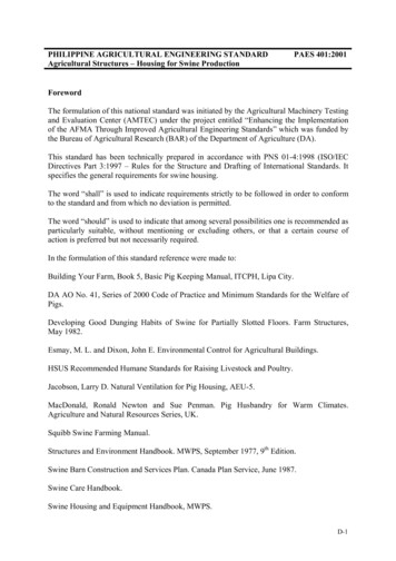
PAES 608:2016 – Part B5Components of Drip Irrigation SystemFigure 1 - A typical drip irrigation system and its componentsSOURCE: Savva and Frenken. FAO Irrigation Manual – Localized Irrigation Systems Planning,Design, Operation and Maintenance. 2002.5.1Control head - consists of valves to control the discharge and pressure in theentire system which may have filters and a a fertilizer or nutrient tank.5.2Pump unit - takes water from the source and provides the right pressure fordelivery into the pipe system5.3Main, submain lines and laterals - supply water from the control head intothe fields which are usually made from PVC or polyethylene hose and should beburied below ground because they easily degrade when exposed to direct solarradiation5.4Manifold – contains filters, pressure regulators, air and/or vacuum reliefvalves5.5Filter – removes particle to prevent emitter clogging where its net diameter issmaller than one-tenth to one-fouth of the emitter opening diameter.5.6Emitters – see section 4.2A-213
PAES 608:2016 – Part B6General Design Criteria6.1Type of Crop –drip irrigation can be used in high value crops such as rowcrops (vegetables, soft fruit), tree and vine crops where one or more emitters can beprovided for each plant.6.2Slope – drip irrigation can be used in any farmable slope where the cropwould be planted along contour lines and the water supply pipes (laterals) would belaid along the contour as well.6.3Soil Type –drip irrigation may be used for most soils.On clay soils, watermust be applied slowly to avoid surface water ponding and runoff. On sandy soilshigher emitter discharge rates will be needed to ensure adequate lateral wetting of thesoil.6.4Irrigation Water –irrigation water shall be free of sediments including algae,fertilizer deposits and dissolved chemicals which precipitate such as calcium and iron.Otherwise, filtration of the irrigation water will be needed.6.5System Layout and Pipe Network6.5.1 The pipe network shall be designed to deliver water to the emitters at theappropriate pressure.6.5.2 The components of the pipe network shall be noncorrosive and non-scalingsuch as polybutylene, polyethylene, or PVC.7Data Requirements7.1 Topographic map – the topographic map shall include the following details:the proposed irrigated area, with contour linesfarm and field boundaries and water source or sourcespower points, such as electricity lines, in relation to water source and area tobe irrigatedroads andother relevant general features such as obstacles Water resources dataquantity and quality of water resources over timewater rightscost of water if applicable 7.27.3cropClimate of the area and its influence on the water requirements of the selected7.4Soil characteristics and their compatibility with the cropsA-214
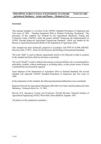
PAES 608:2016 – Part B8Design ProcedureFigure 2 – Design Procedure for a Drip Irrigation System8.1Crop Water Requirement – The water requirement to be considered shall bethe localized evapotranspiration based on the formulae below. This shall be computedon a monthly or decadal basis.ETcrop loc ETa k rwhereETcrop-loc localized evapotranspiration, mm/dayETa actual evapotranspiration, mm/day (estimated as shown in is shown inPAES 602:2016 - Determination of Irrigation Water Requirements)kr ground cover reduction factor (shown in Table 1)A-215
PAES 608:2016 – Part BTable 1 – Values of kr suggested by different authorsGround Cover(%)102030405060708090100Keller Kr according toFreeman Decroix CE: Savva and Frenken, FAO Irrigation Manual – Localized Irrigation Systems Planning,Design, Operation and Maintenance, 2002Formula by Keller and Bliesner may also be used,ETcrop loc ETa [0.1(Pd )0.5 ]whereETcrop-loc localized evapotranspiration, mm/dayETa actual evapotranspiration, mm/day ( estimated as shown in is shown inPAES 602:2016 - Determination of Irrigation Water Requirements)Pd percentage ground cover8.2Leaching RequirementsLR t ECw2 [maxECe ]whereLRt leaching requirement ratio under drip irrigationECw electrical conductivity of irrigation water, ds/m or mmhos/cmmaxECe electrical conductivity of saturated soil extract that will reduce thecrop yield to zero, dS/m or mmhos/cmIR n ETcrop loc R LRLR LR t [IR n]EawhereLR leaching requirement, mm/dayLRt leaching requirement ratio under drip irrigationIRn net irrigation requirement, mm/dayEa application efficiency, %A-216
PAES 608:2016 – Part BTable 2 – Minimum and maximum values of ECe for various cropsCropECe (dS/m)MinMaxField CropsCotton7.7Sugar beet7.0Sorghum6.8Soya bean5.0Sugarcane1.7Fruit and Nut CropsDate palm4.0Fig .7Apple, pear1.7Walnut1.7Peach1.7Vegetable 1.7Crop2724131019CornFlaxBroad beanCow 665.5415Sweet corn1.710Sweet URCE: Keller and Bliesner, Sprinkle and Trickle Irrigation, 19908.3ECe (dS/m)MinMaxIrrigation RequirementIR g ETcrop loc R LREawhereIRg gross irrigation requirement, mm/dayETcrop-loc localized evapotranspiration, mm/dayEa application efficiency, %R rainfall, mm/dayLR leaching requirement,mm/dayA-217
PAES 608:2016 – Part B8.4Percentage Wetted AreaPw 100 Np Se WSp SrwherePw percentage wetted area, %W wetted width or width of wetted strip along lateral with emitters, mSr distance between plant rows or row spacing, m8.5Number of Emitters Per Plant and Emitter SpacingNp Area per plant PwAwwhereNp Number of emitters per plantPw Percentage wetted area/100 (%/100)Aw Area wetted by one emitter, m2Se SpNpwhereSe emitter spacing, mSp distance between the plants within a row, mNp number of emitters per plantAw π D24whereAw area wetted by one emitter, m2D diameter of wetted area, m (see Table 3)8.6Irrigation Frequency and DurationTa IR gNp qwhereTa duration of irrigation per day, hIRg gross irrigation requirement, mm/dayNp number of emitters per plantq emitter discharge, L/hA-218
PAES 608:2016 – Part BTable 3 – Estimated Areas Wetted by a 4 L/h Drip Emitter Operating UnderVarious Field ConditionsSoil or Root Depthand Soil Texture1Depth 0.75 m:CoarseMediumFineDepth 1.50 m:CoarseMediumFineDegree of Soil Stratification2 and Equivalent Wetter SoilArea3 (Se’ x W), m x mhomogeneousstratifiedlayered40.4 x 0.50.7 x 0.90.9 x 1.10.6 x 0.81.0 x 1.21.2 x 1.50.9 x 1.11.2 x 1.51.5 x 1.80.6 x 0.81.0 x 1.21.2 x 1.51.1 x 1.41.7 x 2.11.6 x 2.01.4 x 1.82.2 x 2.72.0 x 2.4NOTE:1 Coarse – coarse to medium sands; Medium – loamy sand to loam; Fine – sandy clay to loamto clay (if clays are cracked, treat like coarse to medium soils)2 Stratified – relatively uniform texture but having some particle orientation or somecompaction layering, which gives higher vertical than horizontal permeability;Layered – changes in texture with depth as well as particle orientation and moderatecompaction3 W – long area dimension, equal to the wetted diameter; Se’wetted area dimension 0.8 x W4 For soils with extreme layering and compaction that causes extensive stratification, Se’ andW may be as much as twice as largeSOURCE: Savva and Frenken, FAO Irrigation Manual – Localized Irrigation Systems Planning,Design, Operation and Maintenance, 20028.7Emitter Selection - The following parameters shall be considered in selectingthe type of emitter8.7.1 Types of Emitters – Different types of emitters are shown in Annex A.8.7.2 Discharge and Pressure Relationship – a lower value of x indicates that theflow will be less affected by pressure variationsq Kd Hxwhereq emitter discharge, L/hKd discharge coefficient that characterizes each emitterH emitter operating pressure head, mx emitter discharge exponentTable 4 – Emitter Discharge Exponents for Various Types of EmitterEmitter TypexFully-compensating emitter0Long-path emitter0.7-0.8Tortuous-path emitter0.5-0.7Orifice type emitter0.5Vortex emitter0.4SOURCE: Savva and Frenken, FAO Irrigation Manual – Localized Irrigation Systems Planning,Design, Operation and Maintenance, 2002A-219
PAES 608:2016 – Part B8.7.3 Coefficient of VariationTable 5 – Coefficient of Variation for Different Emitter TypesEmitter TypeCv RangeClassificationPoint-source 0.05excellent0.05 to 0.07average0.07 to 0.11marginal0.11 to 0.15poor 0.15unacceptableLine-source 0.10good0.10 to 0.2average 0.2marginal to unacceptableNote: While some literature differentiates between ‘point-source’ and ‘line-source’,based on the distance between the emitters, in this Module the difference is based onthe material used for the dripline or lateral. The thick wall material is considered asbeing ‘point-source’, while the tape type of material is considered as being ‘linesource’.SOURCE: Savva and Frenken, FAO Irrigation Manual – Localized Irrigation Systems Planning,Design, Operation and Maintenance, 20028.7.4 Temperature and Discharge Relationship – as an emitter is subjected to ahigher temperature, discharge increases as well, except for vortex-type emitter8.7.5 Head and Discharge Relationship Between Two Emitters with the SameCharacteristicsHa H [q a 1/x]qwhereqa average emitter flow rate obtainable under pressure Ha, L/hq emitter flow rate obtainable under pressure H, L/hx emitter exponent8.8Design Emission UniformityEU 100 1 1.27Cv Np qmqawhereEU design emission uniformity, %Np number of emitters per plantCv manufacturer’s coefficient of variationqm minimum emitter discharge for minimum pressure in the sub-unit, L/hqa average or design emitter discharge for the sub-unit, L/hA-220
PAES 608:2016 – Part B8.9Allowable Pressure Variation Hs 2.5 (Ha Hm )1 xqmHm Ha ( )qawhere Hs allowable pressure variation that will give an EU reasonably close tothe desired design value, mHa pressure head that will give the qa required to satisfy EU, mHm pressure head that will give the required qm to satisfy EU, m8.10 Pipe Size Determination - pipe sizes shall be selected depending on thelayout, selected material and number of outlets. These pipes shall not exceed theallowable pressure variation.8.10.1 Friction Loss in Main Lines – can be determined using Hazen-WilliamsEquation, Darcy Weisbach or other friction loss formula. The formula given below isbased on Hazen WilliamsQ 1.852Hf 1.21 1010 L ( C )D4.87where:Hf total friction loss in pipe with the same flow throughout, mL length of pipe, mQ total discharge, L/sC pipe roughness coefficient145 to 150 for plastic pipe120 for aluminum pipe with couplers and new or coated steel pipeD inside diameter of pipe, mm8.10.2 Friction Loss in Laterals and Manifoldshf Hf Fwherehf friction loss in the lateral, mHf total friction loss in pipe with the same flow throughout, mF correction factor depending on the number of outlets in the lateral ormanifold (Table 6)A-221
PAES 608:2016 – Part BTable 6– F factors for various number of outletsNumber of .4150.4020.394Number of 710.3680.3640.3610.356SOURCE: Savva and Frenken, FAO Irrigation Manual – Localized Irrigation Systems Planning,Design, Operation and Maintenance, 20028.11 Total Head Requirement - The total head requirement shall be computed asthe sum of the following: Suction liftSupply lineControl headMainlineManifoldLateralsOperating pressure10% of the sum of the above heads for fittingsDifference in elevation8.12 Pump and Power Selection – the pump power requirement shall be computedas follows:P Q TDH360 EpwhereP power requirement, kWQ system capacity, m3/hTDH total dynamic head against which the pump is working, mEp pump efficiency from the pump performance chartA-222
PAES 608:2016 – Part BANNEX ATypes of Emitters(Informative)B.1Based on pressure dissipation mechanismB.1.1 Long–path – water is routed through a long, narrow passage at laminar flowto reduce the water pressure and to create a more uniform flow; flow areas: 1 mm2 to4.5 mm2.Figure 1 – Long-Path EmitterSOURCE: NRCS-USDA, Part 652: Irrigation Guide – National Engineering Handbook, 1997B.1.2 Tortuous – have relatively long flow paths with larger path cross-section withturbulent flow regimeFigure 2 – Tortuous-Path EmitterSOURCE: NRCS-USDA, Part 652: Irrigation Guide – National Engineering Handbook, 1997B.1.3 Short-path – almost similar with long-path emitters but with shorter waterpath; ideal for use in very low pressure systems.Figure 3 – Short-Path EmitterSOURCE: NRCS-USDA, Part 652: Irrigation Guide – National Engineering Handbook, 1997A-223
PAES 608:2016 – Part BB.1.4 Orifice – the fully turbulent jet emitted at the outlet of the emitter is brokenand converted into drop by drop flow; flow area: 0.2 mm2 to 0.35 mm2Figure 4 – Orifice Type EmitterSOURCE: NRCS-USDA, Part 652: Irrigation Guide – National Engineering Handbook, 1997B.1.5 Vortex – its flow path is a round cell that causes circular flow. The fastrotational motion creates a vortex which results to higher head losses that allow forlarger openingsB.2Based on the ability to flushB.2.1 On-off flushing – flushes for a few moments each time the system is startedand again when turned offB.2.2 Continuous flushing – eject large particles during operation since this typehas relatively large-diameter flexible orifices in series to dissipate pressureB.3Based on the connection to the lateralB.3.1 On-line – intended for direct or indirect installation in the wall of theirrigation lateralFigure 5 – On-Line EmitterSOURCE: Savva and Frenken, FAO Irrigation Manual – Localized Irrigation Systems Planning,Design, Operation and Maintenance, 2002A-224
PAES 608:2016 – Part BB.3.2 In-line – intended for installation between lateralsFigure 6 – On-Line EmitterSOURCE: Savva and Frenken, FAO Irrigation Manual – Localized Irrigation Systems Planning,Design, Operation and Maintenance, 2002B.4Based on field applicationB.4.1 Line-source – water is discharged from closely spaced perforations, emittersor a porous wall along the lateral line.B.4.2 Point-source – water is discharged from emission points that are individuallyand relatively widely spaced, usually over 1 m (3.3ft). Multiple-outlet emittersdischarge water at two or more emission points.A-225
PAES 608:2016 – Part BANNEX BSample Computation(Informative)ParameterValueArea to be irrigated, ASoilCropActual Evapotranspiration, ETaPercentage groundcoverRainfallApplication EfficiencyTree spacing, area per plantPercentage Wetted Area, PwArea wetted by one emitter, AwB.1300 m x 150 mLoamyMature Citrus7.1 mm/day70%00.866mx6m50%4 m2Compute for the crop water requirement.ETcrop loc ETa k r 7.1 0.82 5.8 mm/day (Keller and Karmelli)6.04 mm/day (Freeman and Garzoli)5.7 mm/day (Decroix CTGREF)5.9 mm/day (Keller and Bliesner)ETcrop loc ETa [0.1(Pd )0.5 ] 7.1 [0.1(0.7)0.5 ] 5.9 mm/dayB.2Compute for the irrigation requirements.mmIR n ETcrop loc R LR 6.0 0 LR 6.04 day LRIR g B.3IRnEa 6.04mm LRday0.86mm 7.02 day LRCompute for the leaching requirement.LR t ECw2 [maxECe ] 22 [8] 0.13IRLR LR t [ E n] 0.13 [7.02] 0.91aB.4Compute for the irrigation requirements.mmIR n ETcrop loc R LR 6.0 0 0.91 6.95 daymmmmIR g 7.02 day LR 7.93 dayB.5Determine the number of emitters per plantNp Area per plant PwAw (6 x 6) 0.54 4.5 or 5 emittersA-226
PAES 608:2016 – Part BB.6Determine the emitter spacing.Se B.7SpNp6 5 1.2 mCheck to see if Pw is within the recommended limit.100 Np Se WPw Sp Sr 100 5 1.2 2.266 6 38%Lower Pw suggests that one line of emitter is not satisfactory. Because of this,use two emitter lines. For uniformity, add another emitter. Moreover, adjustthe wetted width between the laterals, where the spacing between the lateralsshould not excedd 80% of the wetted width 0.8 2.26 1.81100 Np Se WPw B.8Sp Sr 100 6 1.2 1.816 6 60%Compute for the irrigation frequency and duration. Choose from the optionsbelow for the operation.mmIR g 7.03 day 6m 6m Ta IRgNp q 285 5.946 8hdaym3tree0.285day 285Ltree/dayfor 8 L/h drippersTa 7.92 h/day for 6 L/h dripperTa 11.88 h/day for 4 L/h dripperB.8.1 6 L/h dripper with 2 sub-units operating for 15.8 h/dayB.8.2 8 L/h dripper with 3 sub-units operating for 17.8 h/day, as long as no runoffoccursB.8.3 4 L/h dripper with increased discharge by sligtly increasing the pressure suchthat Ta 11 h/day, q 4.32 L/h operating for 22 h/dayB.9Select a 4 L/h emitter for option B.8.3. From manufacturer’s catalogues,x 0.42, q 4 L/h at H 10 m, Cv 0.07.B.10Determine the pressure required to deliver 4.32 L/h.q1/xHa H [ qa ]B.11 10 [4.32 1/0.424] 12.0 mDetermine qm such that EU of 90% will be attained.qm EU qa1 1.27Cv100 Npqm1 xHm Ha ( q )a 90 4.32100 1 1.27 0.07 64.03 12 (4.32) 4.03 L/h1 0.42A-227 10.2 m
PAES 608:2016 – Part BB.12Compute for the allowable pressure variation. Hs 2.5 (Ha Hm ) 2.5 (12 10.2) 4.5 mThe design process provisions should be made so that the head losses andelevation difference within each hydraulic unit do not exceed the 4.5 m.B.13Compute for the allowable pressure variation when EU 95%, Hs 1.0 m.B.14Layout the pipe network.B.15Determine the size of laterals, manifolds and mainline.B.15.1 Lateral – Since there are 6 emitters per plant, 3 emitters per lateral will beconsidered. The first row of plants will start half the spacing from the boundary. Theemitters are of in-line type which losses are equivalent to 0.22 m per emitter.NpLQ No. of trees q a plant 25 4.32 3 324 h 0.09 L/sL 148 m; F 0.358 (75 outlets);C 150 (soft polyethylene pipe); D 16mm0.09 1.852hf 0.358 1.21 1010 148 ( 150 )164.87 0.946 mAdding the losses from the emitter: hf 0.946 m 0.156 m 1.1 mThe selected size for the laterals is acceptable.The remaining head for maintaining the allowable pressure variation of 4.5mis 3.4 m.B.15.2 Manifolds – There will be 4 manifolds (M1, M2, M3, M4) where 2 operates at atime so that the total irrigation duration is 22 hours. M1 and M3 will supply 13 rows(26 laterals) while M3 and M4 will supply 12 rows (24 laterals). Additional 10% headloss will be added to account for the manifold-to lateral connection.ParameterQ (L/s)L (m)FC (uPVC 4)D (mm)hf (m)Elevation Difference (m)Total 0.372150500.740.701.44Since the maximum head in the manifold is less than the remaining allowablepressure variation, the selected size for the manifolds is acceptable.A-228
PAES 608:2016 – Part BB.15.3 Main – It should be sized such that it will allow for the separate use of the firsttwo manifolds from the last two manifolds. Consider 2 cases:Case 1: Last 2 manifolds in operation (M3 and M4)D 75 mmL 150 m (distance between M1 and M3)C 150 (uPVC 4)Q Q3 Q4 4.5 L/sHf 2.03 mD 63 mmL 78 m (distance between M3 and M4)C 150 (uPVC 4)Q4 2.16 L/sHf 0.63 mTotal Hf 2.66 mCase 2: First 2 manifolds in operation (M1 and M2) Since M1 offtake is at thebeginning of the mainline, the flow in the mainline will be the flow required inM2 .D 75 mmL 75 mC 150 (uPVC 4)Q2 2.16 L/sHf 0.34 mSize the mainline based on Case 1.B.15.4 Compute for the total head requirement.ComponentSuction LiftSupply LineControl HeadHead (m)2.000.407.00MainlineManifoldLateralsOperating PressureSUBTOTALFittingsElevation DifferenceTOTALRemarksAssumedD 75 mm; L 25 mAssumed based on filtrationchemigation requirement2.660.921.112.0026.082.68.2036.9B.15.5 Compute for the power requirement. Assume Ep 55%P Q TDH360 Ep 16.2 36.9360 0.55 3.02 kWA-229and
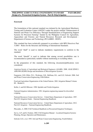
PAES 608:2016 – Part BFigure C.1 – Field MapA-230
Design, Operation and Maintenance, 2002 Formula by Keller and Bliesner may also be used, Tcrop loc Ta 0 [0.1(Pd).5] where ET crop-loc localized evapotranspiration, mm/day ET a actual evapotranspiration, mm/day ( estimated as shown in is shown in PAES 602:2016 - Determination of Irrigation Water Requirements) P d percentage ground cover