Transcription
FAILURE AND CRITICALITYANALYSISME 481 Senior Design IFall 2020Dr. Trevor C. Sorensen
The Engineer’sCrystal BallT. Sorensen, M. NejhadME 481 – Fall 20202 of 57
The Engineer’s Crystal Ball Quality is a relative term often based on customerperception or the degree to which a product meetscustomer expectations Traditionally quality activities have focused ondetecting manufacturing and material defects thatcause failures early in the life cycle Today, activities focus on finding and preventingfailures before they can occurEmphasis on Failure PreventionT. Sorensen, M. NejhadME 481 – Fall 20203 of 57
The Engineer’s Crystal BallInfant MortalityNormal (Useful) LifeEnd-of-LifeDecreasing Failure RateLow Random Failure RateIncreasing Failure RateT. Sorensen, M. NejhadME 481 – Fall 20204 of 57
The Engineer’s Crystal BallT. Sorensen, M. NejhadME 481 – Fall 20205 of 57
The Engineer’s Crystal BallRELIABILITY/FAULT ANALYSIS PROCEDURESHW/SW ANDHUMAN ERRORSHARDWARE/SOFTWAREFAILUREST. Sorensen, M. NejhadME 481 – Fall 20206 of 57
The Engineer’s Crystal BallFault TreetT. Sorensen, M. NejhadME 481 – Fall 20207 of 57
The Engineer’s Crystal BallRELIABILITY/FAULT ANALYSIS PROCEDURESHW/SW ANDHUMAN ERRORSHARDWARE/SOFTWAREFAILUREST. Sorensen, M. NejhadME 481 – Fall 20208 of 57
ReliabilityAnalysisT. Sorensen, M. NejhadME 481 – Fall 20209 of 57
Reliability Analysis Reliability is “the probability that a device willfunction without failure over a specified time periodor amount of usage.” [IEEE, 1984]– basic reliability is for no failure of any kind– mission reliability is for no failure that impairs themission - this is the more important reliability for spacemissions and if no qualifier appears before the word“reliability” it is assumed to mean “mission reliability”– Basic equation for reliability for a single function notsubject to wear-out failures:R e - twhere R is the probability that the item will operate without a failure for time t(success probability) and is the failure rateT. Sorensen, M. NejhadME 481 – Fall 202010 of 57
Reliability Analysis– The probability of failure, F is:F 1-R– For a vehicle made up of n nonredundant elements, allequally essential for vehicle operation, the system (or series)reliability, Rs, is:n- itR s Ri e1where Ri (i 1 n) is the reliability and i the failure rate of individualcomponents.– For failure probabilities ( t) 0.1 or R 0.9, thene- t 1 - tT. Sorensen, M. NejhadME 481 – Fall 202011 of 57
Reliability Analysis– For a system with n elements in parallel where eachof these elements can by itself satisfy therequirements, the parallel (or redundant) reliability,Rp, is given by:nRp 1 - (1 - Ri)1– When the reliability of the parallel elements is equal(Ra) the above equation simplifies to:Rp 1 - ( 1 - Ra)nT. Sorensen, M. NejhadME 481 – Fall 202012 of 57
Reliability AnalysisSeries and Parallel Reliability ModelsT. Sorensen, M. NejhadME 481 – Fall 202013 of 57
Reliability AnalysisEffect of Partitioning on Reliabilityt is the time from start of the missionR is the mission reliability or theprobability that at least essentialmission elements will surviveN is the number of individual blocks is the failure rate of an individualblock 1/MTBF, where MTBF is the meantime between failures for each blockFor the whole system:Rs exp(- st) where s is 1/MTBF forthe whole systemT. Sorensen, M. NejhadME 481 – Fall 202014 of 57
Reliability AnalysisT. Sorensen, M. NejhadME 481 – Fall 202015 of 57
Reliability AnalysisT. Sorensen, M. NejhadME 481 – Fall 202016 of 57
Reliability AnalysisT. Sorensen, M. NejhadME 481 – Fall 202017 of 57
Reliability Analysis Design life is the intended operational time ofmission– important parameter for reliability program– determines amount of consumables that must be provided– establishes quality and test requirements for items subjectto wear-out (e.g., batteries, solar cells, bearings)– mission reliability calculated at the design life is themission success probability ( 1.0)– Expected life is less than the design life– Mean mission duration, MMD, given by:MMD TdRwhere T is horiz. time line and dR is the associated increment in reliability– MMD expresses avg. mission duration at 100% reliability– MMD is frequently used as a FoM for reliabilityT. Sorensen, M. NejhadME 481 – Fall 202018 of 57
Reliability Analysis Mission effectiveness is a single metric thatrepresents the reliability weighted by the operationalcapability level to which that reliability is applicable– mission effectiveness gives credit for what a vehicle canstill do after a partial failure– can be used as an alternative to mission reliability tobetter express what is really required– specifying mission effectiveness generally reduces bothcost and development time compared to specifyingmultiple reliability values– effectiveness curve will lie above the reliability curvewhen the latter is constructed for the entire system– complement of mission effectiveness (area aboveeffectiveness curve) represents the failure probabilityweighted by the consequence of the failureT. Sorensen, M. NejhadME 481 – Fall 202019 of 57
Reliability AnalysisFrequently Used Reliability ConceptsAvg. reliability RdtMMD TdRMMD is Mean Mission DurationDesign life is governed by wear-out and expendable stores. Mean mission duration is less thandesign life because failures can terminate a mission before end-of-life conditions are reached. tT. Sorensen, M. NejhadME 481 – Fall 202020 of 57
The Engineer’s Crystal BallRELIABILITY/FAULT ANALYSIS PROCEDURESHW/SW ANDHUMAN ERRORSHARDWARE/SOFTWAREFAILUREST. Sorensen, M. NejhadME 481 – Fall 202021 of 57
Failure Mode & Effects Analysis(FMEA)Failure Mode, Effects & CriticalityAnalysis (FMECA)T. Sorensen, M. NejhadME 481 – Fall 202022 of 57
FMEA/FMECADefinition A methodology to analyze and discover:– All potential failure modes of a system– The effects these failures have on the system– How to correct or mitigate the failures or effects on the system FMEA and CIL (Critical Items List) evaluations also crosscheck safety hazard analyses for completeness Together FMEA and CIL are sometimes call Fault Modes,Effect, and Criticality Analysis (FMECA)T. Sorensen, M. NejhadME 481 – Fall 202023 of 57
FMEA/FMECABenefits FMECA is one of the most important tools of reliabilityanalysis and failure prevention– If done early enough in the design process it can havetremendous impact on removing causes for failure of developingsystems that can mitigate their effects.– FMECA exposes single point failure modes in a subsystemassumed to be redundant– FMECA identifies opportunities for functional redundancy– FEMCA permits components to assume a safe mode in theabsence of required signals or power– Failures are usually recorded at the part levelT. Sorensen, M. NejhadME 481 – Fall 202024 of 57
FMEA/FMECABenefits Cost benefits associated with FMECA are usually expected tocome from the ability to identify failure modes earlier in theprocess, when they are less expensive to address.– “rule of ten” If the issue costs 100 when it is discovered in the field,then It may cost 10 if discovered during the final test But it may cost 1 if discovered during an incominginspection. Even better it may cost 0.10 if discovered during thedesign or process engineering phase.T. Sorensen, M. NejhadME 481 – Fall 202025 of 57
FMEA/FMECAHistory The history of FMEA/FMECA goes back tothe early 1950s and 1960s.– U.S. Navy Bureau of Aeronautics, followed bythe Bureau of Naval Weapons– National Aeronautics and SpaceAdministration (NASA) Department of Defense developed andrevised the MIL-STD-1629A guidelinesduring the 1970s.T. Sorensen, M. NejhadME 481 – Fall 202026 of 57
FMEA/FMECAHistory (cont.) Ford Motor Company published instructionmanuals in the 1980s and the automotiveindustry collectively developed standards inthe 1990s. Engineers in a variety of industries haveadopted and adapted the tool over the years.T. Sorensen, M. NejhadME 481 – Fall 202027 of 57
FMEA/FMECAPublished Guidelines J1739 from the SAE for the automotive industry. AIAG FMEA-3 from the Automotive Industry ActionGroup for the automotive industry. ARP5580 from the SAE for non-automotive applications. Other industry and company-specific guidelines exist.For example:– EIA/JEP131 provides guidelines for the electronicsindustry, from the JEDEC/EIA.– P-302-720 provides guidelines for NASA’s GSFCspacecraft and instruments.– SEMATECH 92020963A-ENG for the semiconductorequipment industry.T. Sorensen, M. NejhadME 481 – Fall 202028 of 57
FMEA/FMECASFMEA, DFMEA, and PFMEA When it is applied to interaction of parts it is calledSystem Failure Mode and Effects Analysis (SFMEA) Applied to a product it is called a Design Failure Modeand Effects Analysis (DFMEA) Applied to a process it is called a Process Failure Modeand Effects Analysis (PFMEA).T. Sorensen, M. NejhadME 481 – Fall 202029 of 57
FMEA/FMECARelationship Between SFMEA, DFMEA, and PFMEASYSTEMDESIGNPROCESSMain SystemsSubsystemsComponentsMain SystemsSubsystemsComponentsFocusFocusMinimize failureeffects on theSystemMinimize failureeffects on nvironmentObjectivesObjectivesMaximizeSystem quality,reliabilityReduce cost andmaintenanceMaximize Designquality, reliabilityReduce cost andmaintenanceT. Sorensen, M. NejhadME 481 – Fall 2020FocusMinimize failureeffects on theProcessObjectivesMaximize Processquality, reliabilityReduce cost andmaintenance30 of 57
FMEA/FMECAFMEA/FMECA in Systems EngineeringT. Sorensen, M. NejhadME 481 – Fall 202031 of 57
FMEA/FMECAFMEA/FMECA Procedure FlowchartT. Sorensen, M. NejhadME 481 – Fall 202032 of 57
FMEA/FMECAFMEA/FMECA Procedure1.Review the design or process– Determine function of all components– Create functional and reliability block diagrams– Document all environments and missions of system2.3.4.5.6.7.8.9.10.Brainstorm potential failure modesList potential failure effectsAssign severity ratingsIdentify potential causes of each failure modeAssign occurrence ratingsList current controls for each causeAssign a detection ratingsCalculate the Risk Priority Number (RPN)Determine criticality of the failure, ranking & CIL– Develop Critical Items List (CIL)11. Develop action plan for follow-up or corrective actions12. Take action and reevaluate RPNT. Sorensen, M. NejhadME 481 – Fall 202033 of 57
FMEA/FMECAStep 2: Failure Modes Definition: the manner in which a system, subsystem, or componentcould potentially fail to meet design intent In what ways can they fail? How likely is this failure? Do one or more components interact to produce a failure? Is this a common failure? Who is familiar with this particular item?Remember to consider:absolute failurepartial failureintermittent failureover functiondegraded functionunintended functionT. Sorensen, M. NejhadConsider potential failure modes under:Operating Conditions:o hot and coldo wet and dryo dusty and dirtyUsage:o above average life cycleo harsh environmento below average life cycleME 481 – Fall 202034 of 57
FMEA/FMECAStep 3: Potential Failure Effects Definition: Effects of the failure mode on the function asperceived by the customer/user Ask yourself- ”What would be the result of this failure?”or “If the failure occurs then what are the consequences” Describe the effects in terms of what the customer mightexperience or notice State clearly if the function could impact safety ornoncompliance to regulations Identify all potential customers. The customer may be aninternal customer, a distributor as well as an end user Describe in terms of product performanceT. Sorensen, M. NejhadME 481 – Fall 202035 of 57
FMEA/FMECAStep 3: Examples of Failure Effects noise loss of fluid seizure of adjacentsurfaces loss of function no/low output loss of systemT. Sorensen, M. Nejhad intermittent operationsrough surfaceunpleasant odorpoor appearancepotential safety hazardcustomer dissatisfiedME 481 – Fall 202036 of 57
FMEA/FMECA Step 4: SeverityDefinition: assessment of the seriousness of the effect(s)of the potential failure mode on the next component,subsystem, or customer if it occursSeverity applies to effectsFor failure modes with multiple effects, rate each effectand select the highest rating as severity for failure modeTypical scale: 1 Not Severe to 10 Very Severe1510 Examples (for car):– Cannot see out of front window – severity 9– Does not get warm enough – severity 5T. Sorensen, M. NejhadME 481 – Fall 202037 of 57
FMEA/FMECAStep 5: Causes of Failure Modes Definition: an indication of a design weakness,the consequence of which is the failure mode Why do things fail? Every conceivable failure cause or mechanismshould be listed Each cause or mechanism should be listed asconcisely and completely as possible so effortscan be aimed at pertinent causesT. Sorensen, M. NejhadME 481 – Fall 202038 of 57
FMEA/FMECAStep 5: Examples of Failure Modes Fatigue/fractureStructural overloadElectrical overloadWear (lube failure or contamination)Seal failureChemical attackOxidationMaterial removalRadiationSoftware errorsEtc.T. Sorensen, M. NejhadME 481 – Fall 202039 of 57
FMEA/FMECAStep 6: Occurrence Definition: likelihood that a specific cause/ mechanismwill occur and create failure modes Obtain from past data if possible Removing or controlling the cause/mechanism through adesign change is the only way to reduce the occurrencerating Typical scale: 1 Not Likely to 10 Very Likely1T. Sorensen, M. Nejhad5ME 481 – Fall 20201040 of 57
FMEA/FMECAStep 7: Current Controls Definition: activities which will assure the design adequacy for thefailure cause/mechanism under consideration Confidence Current Design Controls will detect cause andsubsequent failure mode prior to production, and/or will preventthe cause from occurring– If there are more than one control, rate each and select the lowest for thedetection rating Control must be allocated in the plan to be listed, otherwise it’s arecommended action Two types of Controls1. Prevention from occurring or reduction of rate2. Detection– detect cause mechanism and lead to corrective actions– detect the failure mode, leading to corrective actionsT. Sorensen, M. NejhadME 481 – Fall 202041 of 57
FMEA/FMECAStep 7: Examples of Current Controls Type P control Type D controls– Warnings which alertproduct user to impendingfailure– Fail/safe features– Designprocedures/guidelines/specificationsT. Sorensen, M. NejhadME 481 – Fall 2020––––––––Road testDesign ReviewEnvironmental testFleet testLab testField testLife cycle testLoad test42 of 57
FMEA/FMECAStep 8: Detection Definition: Detection is the value assigned toeach of the detective controls If detection values are based upon internallydefined criteria, a reference must be included inFMECA to rating table with explanation for use Detection values of 1 must eliminate the potentialfor failures due to design deficiency Typical scale:1 Easy to Detect to 10 Difficult to Detect1T. Sorensen, M. Nejhad5ME 481 – Fall 20201043 of 57
FMEA/FMECAStep 9: Risk Priority Number (RPN) Definition: RPN is the product of severity, occurrence,and detection scores Lowest detection rating is used to determine RPNSeverityX Occurrence XDetection RPN RPN is used to prioritize concerns/actions The greater the value of the RPN the greater theconcern RPN ranges from 1-1000 The team must make efforts to reduce higher RPNsthrough corrective action General guideline is over 100 recommended actionT. Sorensen, M. NejhadME 481 – Fall 202044 of 57
FMEA/FMECAStep 10: Criticality and CIL Assign criticality categories based on redundancy,results of failure, safety, etc. Develop criteria for what failure modes are to beincluded in a Critical Items List (CIL) Develop screens to evaluate redundancy Analyze each critical item for ways to remove it, ordevelop “retention rationale” to support the premise thatthe risk be retained Cross check critical items with hazard reportsT. Sorensen, M. NejhadME 481 – Fall 202045 of 57
FMEA/FMECAStep 10: Criticality Categories (Typical) 1 – Single failure point that could result in loss of vehicle orpersonnel 1R – Redundant items, where if all failed, the result would beloss of vehicle or personnel 1S – A single point of a system component designed to providesafety or protection capability against a potential hazardouscondition or a single point failure in a safety monitoring system(e.g., fire suppression system) 1SR – Redundant components, where if all failed, the result issame as 1S above 2 – Single point of failure that could result in loss of criticalmission support capability 3 – All otherT. Sorensen, M. NejhadME 481 – Fall 202046 of 57
FMEA/FMECAStep 10: Analyze Critical Items Prepare retention rationale for item– What current design features minimize the probability ofoccurrence?– What tests can detect failure modes during acceptance tests,certification tests, checkout for operation?– What inspections can be performed to prevent the failuremode from being manufactured into hardware?– What failure history justifies the CIL retention?– How does operational use of the unit mitigate the hardwarefailure effect?– How does maintainability prevent the failure mode?T. Sorensen, M. NejhadME 481 – Fall 202047 of 57
FMEA/FMECAStep 11: Actions Recommended Definition: tasks recommended for the purpose of reducing anyor all of the rankings Only design revision can bring about a reduction in the severityranking All critical or significant characteristics must have recommendedactions associated with them Recommended actions should be focused on design, and directedtoward mitigating the cause of failure, or eliminating the failuremode If recommended actions cannot mitigate or eliminate the potentialfor failure, recommended actions must force characteristics to beforwarded to process FMEA for process mitigationT. Sorensen, M. NejhadME 481 – Fall 202048 of 57
FMEA/FMECAStep 11: Examples of Actions Perform:– Designed experiments– Reliability testing– Finite element analysis Revise design– Revise test plan– Revise material specificationT. Sorensen, M. NejhadME 481 – Fall 202049 of 57
FMEA/FMECAStep 12: Action and Reevaluation All recommended actions must have a person assignedresponsibility for completion of the action Responsibility should be a name, not a title There must be a completion date accompanying eachrecommended action Unless the failure mode has been eliminated, severity should notchange Occurrence may or may not be lowered based upon the results ofactions Detection may or may not be lowered based upon the results ofactions If severity, occurrence or detection ratings are not improved,additional recommended actions must be definedT. Sorensen, M. NejhadME 481 – Fall 202050 of 57
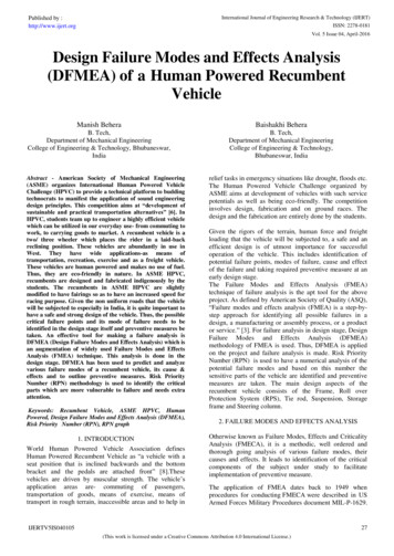
51FMEA/FMECATypical FMEA FormNote: FMECA Form would have CIL column after RPNIdentify failure modesand their effectsT. Sorensen, M. NejhadIdentify causes of thefailure modesand controlsME 481 – Fall 2020PrioritizeDetermine andassess actions51 of 57
FMEA/FMECAGeneral Instructions for FMECA Document Every FMECA should have an assumptions documentattached (electronically if possible) or the first line ofthe FMECA should detail the assumptions and ratingsused for the FMECA. Product/part names and numbers must be detailed in theFMECA header All team members must be listed in the FMECA header Revision date, as appropriate, must be documented inthe FMECA headerT. Sorensen, M. NejhadME 481 – Fall 202052 of 57
FMEA/FMECAT. Sorensen, M. NejhadME 481 – Fall 202053 of 57
FMEA/FMECAShort Term Uses of FMEA/FMECAT. Sorensen, M. NejhadME 481 – Fall 202054 of 57
FMEA/FMECALong Term Uses of FMEA/FMECAT. Sorensen, M. NejhadME 481 – Fall 202055 of 57
Bibliography MIL-STD-1629A , Procedures for Performing a Failure Mode, Effectsand Criticality Analysis, Nov. 1980. Sittsamer, Risk Based Error-Proofing, The Luminous Group, 2000 MIL-STD-882B, 1984. O’Conner, Practical Reliability Engineering, 3rd edition, Revised, JohnWiley & Sons,Chichester, England, 1996. QS9000 FMEA reference manual (SAE J 1739) Wertz, Everett, and Puschell (ed.), Space Mission Engineering: The NewSMAD, Microcosm Press, Hawthorne, CA, 2011/ McDerrmot, Mikulak, and Beauregard, The Basics of FMEA,Productivity Inc., 1996. TM 5-698-4, Failure Modes, Effects and Criticality Analysis (FMECA)for Command, Control, Communications, Computer, Intelligence,Surveillance, and Reconnaissance (C4ISR) Facilities, HQ, Departmentof the Army, September, 2006.T. Sorensen, M. NejhadME 481 – Fall 202056 of 57
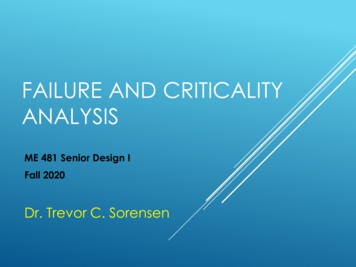
Space Spectaculars!STS-98 Launch2/7/2001MMIII LaunchVAFB 9/19/02Clementine’s View ofEarth Over Lunar NorthPole Mar. 1994T. Sorensen, M. NejhadME 481 – Fall 202057 of 57
Backup SlidesT. Sorensen, M. NejhadME 481 – Fall 202058 of 57
Alternative FMECA Form - 1T. Sorensen, M. NejhadME 481 – Fall 202059 of 57
Alternative FMECA Form - 2T. Sorensen, M. NejhadME 481 – Fall 202060 of 57
The Engineer’s Crystal BallRELIABILITY/FAULT ANALYSIS PROCEDUREST. Sorensen, M. NejhadME 481 – Fall 202061 of 57
Operational ErrorsT. Sorensen, M. NejhadME 481 – Fall 202062 of 57
Operational ErrorsT. Sorensen, M. NejhadME 481 – Fall 202063 of 57
Operational ErrorsT. Sorensen, M. NejhadME 481 – Fall 202064 of 57
Design for ReliabilityT. Sorensen, M. NejhadME 481 – Fall 202065 of 57
Design for Reliability Reliability Program Plan (RPP) specifies thereliability objectives, assigns responsibility forachieving them, and establishes milestones forevaluating the achievements– RPP adds little to the cost of the program and is usefulfor even the smallest spacecraft programs– RPP serves as an agreement with other spacecraftfunctions regarding their responsibilities in support ofreliability– Most significant interfaces are with quality assurance,test, configuration management, and thermal controlT. Sorensen, M. NejhadME 481 – Fall 202066 of 57
Design for Reliability Failure Reporting and Corrective Actions (FRACAS)– FRACAS informs concerned parties that a failure has beenobserved– FRACAS furnishes a record through which trends andcorrelations can be evaluated at a future time– FRACAS permits reassessment of the predicted failure ratesand is the basis for consequent modifications of the faultavoidance or fault tolerance provisions– an operating log is maintained for each part number withseparate records for each serial number– To establish a FRACAS the following must be identified: Scope of the activities (e.g., system test, field test, normal usage) Responsibility for cost and for report initiation Method and frequency of reporting (e.g., paper or electronic, eachincident or by time interval)T. Sorensen, M. NejhadME 481 – Fall 202067 of 57
Design for Reliability– A typical FRACAS will contain the following information: Incident identification number (e.g., report serial number)Date, time and locale of the incidentPart no., name of the failed component, and its serial numberHigher level part or system identifiers (subsystem or majorcomponent)Lower level part or system identifiers (usually available only afterdiagnosis)Operation in progress and environmental conditions when failure wasdetectedImmediate and higher level effects of failureNames of individuals responsible for detection, verification, andanalysisDiagnosis of immediate, contributory and root causes of the failureDates and nature of repair and results of retestT. Sorensen, M. NejhadME 481 – Fall 202068 of 57
Design for ReliabilityRepresentative Piece Part Failure Rates for High Reliability PartsValues are the failure rate, (failures in 109 hours)T. Sorensen, M. NejhadME 481 – Fall 202069 of 57
Design for Reliability Mission failure probability is allocated to subsystemsand adjusted whenever requirements change– Allocation based on prior experience or uniformly tomajor subsystems– Weak link is a recognized subsystem whose complexity ordegree of innovation will contribute greatly to the failureprobability– The failure/value ratio, F/V, is the probability of missionfailure, F, for a subsystem divided by its estimatedresource requirements, VE F/VT. Sorensen, M. NejhadME 481 – Fall 202070 of 57
Design for ReliabilityReliability Allocation to SubsystemsIn the allocation process,the values of F and V mustboth sum to those in thebox from which they wereallocatedValues shown are F, Vand E ( F/V)T. Sorensen, M. NejhadME 481 – Fall 202071 of 57
Design for ReliabilityFailure Prevention Major causes of failures are workmanship anddesign– workmanship can be controlled by quality assurance– design failures occur primarily because: the strength of the component is not adequate for the theenvironment in which it is used, or the manufacturing process allows too much variability incomponent characteristics– Design failures can be controlled by allowingsufficient design margin and performing extensivetestingT. Sorensen, M. NejhadME 481 – Fall 202072 of 57
Design for ReliabilityNote: RMA is Reliability, Maintainability, AvailabilityT. Sorensen, M. NejhadME 481 – Fall 202073 of 57
Design for ReliabilityT. Sorensen, M. NejhadME 481 – Fall 202074 of 57
Design for ReliabilityRedundancy Strategies for Fault ToleranceT. Sorensen, M. NejhadME 481 – Fall 202075 of 57
Design for ReliabilityAttribute Control by ScreeningScreening rejects parts likely to fail in service.T. Sorensen, M. NejhadME 481 – Fall 202076 of 57
Design for ReliabilityAttribute Control by Process ControlIn a controlled population fewer parts are near theacceptance limit than in a screened population.T. Sorensen, M. NejhadME 481 – Fall 202077 of 57
Design for ReliabilityFour Possible Outcomes and Their Probabilitiesfrom Two Independent, Probabilistic EventsT. Sorensen, M. NejhadME 481 – Fall 202078 of 57
J1739 from the SAE for the automotive industry. AIAG FMEA-3 from the Automotive Industry Action Group for the automotive industry. ARP5580 from the SAE for non-automotive applications. Other industry and company-specific guidelines exist. For example: -EIA/JEP131 provides guidelines for the electronics industry, from the JEDEC/EIA.