Transcription
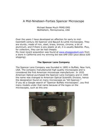
Spencer MultistageFabricated CentrifugalBlowers – SOH,4BOH & 4BOBSerial No:Model No:Operating andMaintenance Manual4BOB Four-Bearing Outboard4BOH Four-Bearing OverhungSOH Standard OverhungImportantRead and become familiar with this manual prior to installing your Spencer blower. Following the instructions detailedhere will help you realize its full potential of efficient service and extended lifespan. Damage resulting from failure to followcorrect procedure will void the warranty.The Spencer Turbine CompanyWindsor, Connecticut 06095Form AA16
ContentsIPageIntroduction . . . . . . . . . . . . . . . . . . . . . . . . . . . . . . . . .2Product Description . . . . . . . . . . . . . . . . . . . . . . . . . .3IILimited Warranty . . . . . . . . . . . . . . . . . . . . . . . . . . . . .3III Safety Precautions & Operating Guidelines . . . . . . .3IV Handling and Storage . . . . . . . . . . . . . . . . . . . . . . . . .4Lifting and Moving . . . . . . . . . . . . . . . . . . . . . . . . . . .4Storage . . . . . . . . . . . . . . . . . . . . . . . . . . . . . . . . . . . .4Unpacking . . . . . . . . . . . . . . . . . . . . . . . . . . . . . . . . .4VInstallation . . . . . . . . . . . . . . . . . . . . . . . . . . . . . . . . . .4Location . . . . . . . . . . . . . . . . . . . . . . . . . . . . . . . . . . .4Foundation . . . . . . . . . . . . . . . . . . . . . . . . . . . . . . . . .4Blower Setup . . . . . . . . . . . . . . . . . . . . . . . . . . . . . . .41. Piping . . . . . . . . . . . . . . . . . . . . . . . . . . . . . . . . . .42. Flexible Connectors . . . . . . . . . . . . . . . . . . . . . . .43. Butterfly Valve . . . . . . . . . . . . . . . . . . . . . . . . . . . .54. Filters, Silencers and Filter Silencers . . . . . . . . . .55. Check Valve . . . . . . . . . . . . . . . . . . . . . . . . . . . . .56. Electrical . . . . . . . . . . . . . . . . . . . . . . . . . . . . . . . .57. Coupling Alignment . . . . . . . . . . . . . . . . . . . . . . . .58. Shaft Seals . . . . . . . . . . . . . . . . . . . . . . . . . . . . . .79. Motor Rotation . . . . . . . . . . . . . . . . . . . . . . . . . . .7VI Operation and Adjustments . . . . . . . . . . . . . . . . . . . .7Startup Precautions . . . . . . . . . . . . . . . . . . . . . . . . . .7Blower Startup . . . . . . . . . . . . . . . . . . . . . . . . . . . . . .7Surge . . . . . . . . . . . . . . . . . . . . . . . . . . . . . . . . . . . . .8Normal Operating Limits . . . . . . . . . . . . . . . . . . . . . .8Periodic Operation . . . . . . . . . . . . . . . . . . . . . . . . . . .8Parallel Installation . . . . . . . . . . . . . . . . . . . . . . . . . . .8VII Lubrication . . . . . . . . . . . . . . . . . . . . . . . . . . . . . . . . . .8Motor Bearings . . . . . . . . . . . . . . . . . . . . . . . . . . . . . .8Blower Bearings, 4BOH & 4BOB . . . . . . . . . . . . . . . .8Flexible Couplings, 4BOH & 4BOB . . . . . . . . . . . . . .9VIII Maintenance . . . . . . . . . . . . . . . . . . . . . . . . . . . . . . . . .9Replacement Parts . . . . . . . . . . . . . . . . . . . . . . . . . . .9Equipment Service . . . . . . . . . . . . . . . . . . . . . . . . . . .9Material Safety Data Sheets . . . . . . . . . . . . . . . . . . .9Emergency Service . . . . . . . . . . . . . . . . . . . . . . . . . .9Service and Operating Assistance . . . . . . . . . . . . . . .9SOH Diagram and Recommended Spare Parts . . .10SOH Disassembly/Reassembly Instructions . . . . . .114BOH Diagram and Recommended Spare Parts . .124BOH Disassembly/Reassembly Instructions . . . . .134BOB Diagram and Recommended Spare Parts . . .144BOB Disassembly/Reassembly Instructions . . . . .15IX Troubleshooting Guide . . . . . . . . . . . . . . . . . . . . . . .16Insufficient Air or Gas . . . . . . . . . . . . . . . . . . . . . . . .16Excessive Machine Noise . . . . . . . . . . . . . . . . . . . .17Machine Vibrating . . . . . . . . . . . . . . . . . . . . . . . . . . .17Motor Hot . . . . . . . . . . . . . . . . . . . . . . . . . . . . . . . . .18I. IntroductionWelcome as a Spencer customer and owner of a new centrifugalblower. Your blower incorporates exclusive Spencer engineeringtechnology, based on more than a century of leadership in blowerdesign and manufacture.This manual contains the information you need for handling,installing, operating and maintaining your new equipment correctly,to ensure trouble-free operation and long service life. Pleaseread it thoroughly. Illustrations and instructions contained hereapply to three series of blowers; Standard Overhung (SOH),Four Bearing Overhung (4BOH) and Four Bearing Outboard(4BOB). If you need assistance in determining which model youhave, please consult your Spencer Representative.Your Spencer Representative will also answer any questions youmay have about the procedures or recommendations presentedin this manual. The Spencer Service and Engineering Departmentscan provide assistance as well.Be sure the machine model number and serial number are correctly recorded in the boxes on the front cover of this manual.These numbers may be found on the nameplate (see samplesbelow) located on the machine housing.Having this information easily accessible will expedite partsorders and other communication with the factory. To serve yourmaintenance and repair needs promptly, Spencer maintains alarge inventory of parts for all blower models.Centrifugal BlowerRead instructions before handling and starting equipmentSerial No.Model No.Manufactured under the following Registered Trademarks:62,801; 140,976; 652,701; 1,616,417; 134,026; 341,418;1,348,270; 959,254; 7,218,205; 7,218,284Use Original Factory Parts & ServiceThe Spencer Turbine Company, Windsor, CT 06095800-232-4321 860-688-8361www.spencerturbine.comMade in U.S.A.Plate No. PLN90054Gas BoosterRead instructions before handling and starting equipmentSerial No.Model No.Manufactured under the following Registered Trademarks:62,801; 140,976; 652,701; 134,026; 341,418; 1,348,270;959,254; 595,313; 7,218,205; 7,218,2852Use Original Factory Parts & ServiceThe Spencer Turbine Company, Windsor, CT 06095800-232-4321 860-688-8361www.spencerturbine.comMade in U.S.A.Plate No. PLN90051
Ill. Safety Precautionsand OperatingGuidelines Read and follow all instructions in this manual. If you haveany questions, consult your Spencer Representative. Use appropriately rated lifting equipment for installation,removal or disassembly of heavy components.Product DescriptionStandard Overhung DesignThese Spencer blowers are multistage centrifugal units whichhandle air and other gases, working either as blowers orexhausters. They increase the pressure of the incoming air orgas by guiding it from one stage to the next through diffusers.They are centrifugal because the flow through the blower isturned perpendicular to the axis of rotation.The most prevalent Spencer blower configuration is the standard overhung type which has all the impellers mounted directlyon an extended motor shaft.The four-bearing overhung blower uses a standard shaft motorand an overhung impeller design. The rotating blower assemblyis supported by a rigid ball bearing bracket and shaft, which isconnected to the motor via a flexible coupling.In four-bearing outboard blowers, the impellers are mounted ona shaft supported between two outboard bearings and driven bya standard shaft motor through a flexible coupling.II. Limited WarrantyWe warrant that this product will be free from defects in materialand workmanship for a period of 18 months from date of shipment or 12 months from date of startup, whichever comes first.Within the warranty period, we shall repair or replace, F.O.B.our Factory, such products that are determined by us to bedefective.This warranty will not apply to any product which has been subjected to misuse, negligence or accident, or misapplied orimproperly installed. This warranty will not apply to any productwhich has been disassembled, repaired or otherwise altered byany persons not authorized by the Spencer Service Department.The guarantees of the motor, control and component manufacturers govern the extent of our guarantee on such equipment.Warranty work on motors, controls and components must beauthorized by Spencer and must be performed in an authorizedshop as designated by the motor, control and component manufacturers. The Spencer Turbine Company reserves the right toinvoice all expenses incurred when repairs are made in the fieldat the specific request of a customer. For complete warrantyinformation, refer to Form 706, “Spencer's Terms and Conditionsof Sales.” Remove inlet and discharge covers, silica gel bags and crating materials prior to blower installation. Inspect all openings for tools and foreign matter before connecting accessories or piping. Perform all installing and operating procedures with care,following sound practices to avoid accidents and damage. Avoid climbing on or over the blower; use proper staging andladders for exterior machine access. Be sure isolation pads are placed beneath the blower. Seepage 4. Install flexible connectors on inlet and discharge flanges toisolate piping loads from the blower. Ensure that piping, machine guards and accessories such asfilters or valves are properly installed and fastened. Install a filter on the inlet when the blower is used in pressureservice and keep it clean. Allow only qualified electricians to work on electrical equipment. Lock electrical circuits open and tag them during servicing ofequipment. Align the coupling as instructed on page 5 (4BOH and 4BOBblowers only). Then remove alignment tools and replacecoupling guard before restarting blower. Turn the blower shaft by hand to verify free rotation withoutrubbing or noise. Check motor rotation as instructed on page 7. Do not operate the blower where there is an ambient temperature above 104 F (40 C), unless it has been designed forsuch conditions. Operate blower with sufficient restriction at all times (via connected piping system or throttled butterfly valve) to avoidmotor overloading. Do not allow blower operation in surge (unstable low flow) ordamage may result. Rotate shaft of stored or inactive blowers a few times byhand every week. Use only genuine Spencer parts for repairs and service.3
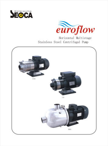
IV. Handling andStorageEach Spencer blower is carefully balanced and tested at thefactory. For optimum performance, it must be handled with careduring unloading and installation.Check the shipment for damage upon arrival; file any claimswith the shipper and notify Spencer.Lifting and MovingMoving of this equipment is the customerʼs responsibility andshould be performed or directed by experienced riggers usingaccepted rigging practices and safety precautions. The blower/motor assembly can be lifted and relocated with a forklift, overhead crane or hoist. Always use lifting equipment rated for theloads involved.Consideration should be given to the noise generated by thisequipment and its contribution to the ambient noise level.Optional noise reduction accessories include blower housingsound attenuation jackets, filter silencers or silencers for theblower inlet and/or discharge, and silencers for the motor.NOTE: Duct noise attenuation is a customer responsibility.FoundationA level concrete pad is recommended, although any flat levelsurface that can support the machine weight is satisfactory. Theblower base should be placed level on the furnished isolationpads or equivalent. Each pad must be shimmed, if necessary,to ensure that it is carrying its share of the load. If lag bolts andnuts are used to restrain the blower, hand-tighten only.NOTE: Spencer does not recommend grouting of machines.InletDischargeCAUTION: Do not lift the blower by its shaft or bearinghousing; use the furnished lifting eyes or slots in theblower base.StorageCheckValveIf a blower is stored for an extended period before use orbetween uses, protect it from dampness, dirt and vibration.Suspend bags of silica gel desiccant in the inlet and discharge.Cover the entire blower if possible or at least cover the inlet anddischarge openings to keep out foreign matter. Rotate the blower shaft a few times by hand every week, keeping a log.FlexibleConnectorsButterflyValveCAUTION: Failure to comply with the required storageprovisions, including weekly shaft rotations, will void thewarranty.Unpacking1. Uncrate the blower, saving all literature, boxes and parts.2. Remove inlet and discharge protective caps and all packingmaterials.3. Use the packing slip to check off and confirm the presenceof all ordered components.4. Read any instructional and warning labels on the machinebefore installation and operation.V. InstallationNOTE: If any problems are encountered during installation orstartup, consult your local Spencer Representative.LocationCAUTION: Do not locate blower or controls where they willbe subject to ambient temperatures above 104 F (40 C)during operation, unless specially equipped for highertemperatures.Spencer blowers may be installed outdoors, preferably undercover, or indoors. When choosing an indoor location, be surethere is sufficient ventilation to allow unrestricted airflow to theblower. In addition, it is advisable to leave several feet of spacearound the blower and motor for ease of servicing. Inaccessibilitycan prove costly.4Blower Setup1" Isolation Pad(shim if necessary)CAUTION: Make sure blower inlet and discharge ports areunobstructed before connecting piping to blower.1. PipingAll piping connected to the blower should be of ample size tominimize frictional loss. All system joints must be airtight; leakypipes waste air and power.All piping must be properly aligned and supported to avoidstress on the blower and restrained to prevent movement awayfrom the blower caused by air pressure. Flexible connectorsmust be used to connect piping to the blower.NOTE: The diagram above shows the proper orientation of apiping elbow in-line with the blower shaft. The butterfly valveshould have its shaft at right angles to the blower shaft and thevalve should open as indicated (counterclockwise in this example). These steps will assure uniform loading of the blowerʼsfirst stage.
2. Flexible ConnectorsCAUTION: Connected piping must not touch the blower.Use flexible connectors (expansion joints or rubber sleeves)on both the inlet and discharge to create an isolating gapbetween blower and piping.3. Butterfly ValveTo regulate (throttle) blower volume and/or pressure, a butterflyvalve may be installed—preferably on the inlet. A valve mayalso be installed on the discharge as an isolation valve.4. Filters, Silencers and Filter SilencersSpencer blowers will accept a filter or filter silencer, typically onthe inlet, and a silencer, typically on the discharge. Inlet filtrationis recommended for pressure applications.5. Check ValveCAUTION: A check valve must be installed in the dischargeline (downstream of any blow-off line) of each blower operating in parallel, or in the inlet line (upstream of any bleedline) of each vacuum producer operating in parallel toprevent reverse flow through idle units.Orient the check valve during installation to equalize loading onthe valve shutters. Usually, the hinge post of the check valveshould be installed perpendicular to the blower shaft. If thecheck valve is installed in a horizontal piping line, position thevalve shaft vertically. Make sure the internal moving parts canmove freely.6. ElectricalNOTE: All wiring and electrical adjustments or installations mustbe done by a qualified electrician in accordance with theNational Electrical Code and local codes.CAUTION: The electrical service at the installation sitemust supply the voltage stamped on the motor nameplate.Operation at an incorrect voltage may damage the motorand void its warranty.In making electrical connections, follow the wiring instructionsfurnished. Wire and fuses should be of ample capacity toensure that proper voltage is maintained at the motor terminalswhile starting and running. It is important that proper startingequipment is used. The starters should have thermal overloadprotection as well as true low-voltage protection.Electrical Accessories. The following optional safety accessories are available from Spencer. For copies of the productbulletins listed, contact your Spencer Representative orwww.spencerturbine.com. Load Control Safety Switch (LCSS)—Bult. No. TDS-223 Electronic Modulating Bleed Control (EMBC)— Bult. No.TDS-224 Bearing Temperature Monitor Control (BTMC)— Bult. No.TDS-222 Standard Blower Safety Control Panels (LCSS, BTMC andVM, Vibration Monitor)—Bult. No. TDS-237 and TDS-236NOTE: Use of a BTMC, vibration monitor and an LCSS orEMBC may be advisable in crucial or unattended applications,anywhere there are wide load fluctuations or where machinesare operating at high pressure or vacuum.Both the LCSS and EMBC are designed to prevent a blower orvacuum producer from operating in a low load (surge) condition.7. Coupling Alignment, 4BOH & 4BOBThe coupling on this machine was carefully aligned at the factoryand the coupling halves and shell(s) marked to indicate optimum relative position. However, transportation may havecaused coupling misalignment.CAUTION: Check the motor and blower shafts for misalignment and carefully realign them if necessary after installation and before startup, as misalignment can causedestructive vibration. Coupling alignment should berechecked again after an hourʼs operation. Final alignmentshould be made at average operating temperature. Aftereach alignment check, add lubricant per instructions andreplace coupling guard.WARNING: DISCONNECT AND LOCK OUT ELECTRICALPOWER BEFORE PERFORMING ALIGNMENT.On certain blowers, the coupling is disassembled after factoryalignment and marking. The coupling halves are specially protected against the elements during shipping. Prior to startup,assemble the coupling, align keyways using factory markingsand lubricate as instructed.Coupling alignment lines up the motor shaft and blower shaft inhorizontal and vertical planes. It also ensures an adequateclearance (gap) between the two coupling halves. Only qualified personnel should attempt to align a coupling. If problemsarise, contact Spencer or your Spencer Representative.Sier Bath Gear-Type Couplings, manufactured to our rigidspecifications, are most commonly supplied with Spencerequipment.Sier BathCoupling Size, in.7/81-1/222-1/233-1/244-1/25Hub to HubGap, in.1/81/81/81/41/41/41/41/41/4Remove one snap ring and slide the sleeve off the hub halves.Using a feeler gage, verify that the gap between the couplinghalves agrees with this table.CAUTION: Some motor shafts are spring-loaded axially. Becareful when using the feeler gage to avoid compressingthe shaft and disturbing the normal at-rest position.Machinery Soft FootImperfections or unevenness between the machine base andany foot of the motor or blower creates a condition known assoft foot, which may be parallel or angular. If uncorrected, softfoot leads to increased stress and high vibration. Although boththe motor and blower feet were preset at the factory, each footmust be checked for soft foot prior to alignment. Any vertical orangular soft foot that exceeds .003” is excessive and must becorrected.5
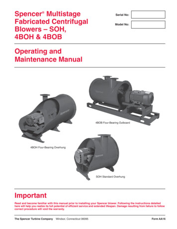
Laser Alignment Technique (Recommended)Laser systems have significant advantages such as reducedmaintenance costs and energy consumption; prolonged life forbearings, seals and couplings; decreased bearing temperaturesand lower vibration levels. Many laser systems also identify andmeasure soft foot conditions.NOTE: Consult an alignment specialist if laser equipment is notavailable.Blower ShaftCAUTION: Complete the following procedures beforeattempting coupling alignment with sleeve bearing motors.Use a flange-type gear coupling for both 1800 and 3600 RPMmotors. Do not use a sleeve-type coupling.Sleeve bearing motors have a specified end play. End play limitsand the magnetic center (where motor will run) should bescribed on the shaft by the manufacturer.Use the following procedure to align a sleeve bearing motorwith a blower.1. Make sure the motor shaft is level.2. Position the motor so that when the rotor is pushed towardthe blower as far as it will go, there will 0.030" clearancebetween the ends of the motor and blower shafts (or thealignment faces on the coupling hubs).Motor ShaftReverse Indicator Method (Permissible)This method may be done electronically following the instrument manufacturerʼs instructions or by means of dial indicatorsas follows:1. Reinstall the coupling sleeve, seal and snap ring.2. Clamp dial indicators on shafts 180 apart as shown.3. Place indicator probes on opposite shafts as shown.4. Rotate both shafts simultaneously in the correct operatingdirection, taking readings at 90 intervals.5. Adjust motor to achieve parallel and angular alignment. Ifquestions arise, contact the Spencer Service Department.3. Proceed with coupling alignment using the appropriateinstructions.Alignment Tips Make sure the blower is level before alignment. Avoid disturbing any factory-installed shims unless they areto be replaced. Mark the axial location of the motor before alignment as areference point to be sure it does not move.Do soft foot corrections first; loosen all mounting bolts beforecorrecting any foot.During the final vertical adjustment of the motor, work onone side at a time, loosening the jack bolts first so the motordoes not move laterally as mounting bolts are loosened. Use the smallest shim that will slide over the mounting bolts.StraightedgeBlower ShaftFeeler GageMotor Shaft Minimize the number of shims. One thick shim and 2-3 thinshims are usually satisfactory. Remove all traces of dirt or contaminants from shims andmachine parts. Use stainless steel shims only. Never reuse shims.StraightedgeMotorShaftStraightedge Method (Permissible)1. Remove old lubricant and clean the hub teeth.2. Set a machine shop quality straightedge across the couplinghubs (at the root diameter of the gear teeth).3. Adjust the motor so the straightedge is evenly supportedbetween the coupling hubs at the 3, 6, 9 and 12 oʼclockpositions.4. Using a feeler gage, measure the clearance between thecoupling hubs at the 3, 6, 9 and 12 oʼclock positions.5. Adjust the motor so the gap is identical at all four positionsand in accord with the table of hub to hub gaps.6Coupling Alignment with Sleeve Bearing MotorsCAUTION: After each alignment check, add coupling lubricant if required.WARNING: REPLACE THE COUPLING GUARD BEFORERESTARTING THE BLOWER.
8. Shaft Seals (SOH, 4BOH, 4BOBBlowers & Gas Boosters)VI. Operation andAdjustmentsStartup PrecautionsBefore operating a new blower for the first time, review itsinstallation and setup to be sure that no steps have been overlooked.1. Installation Check ListCarbon Ring Is there any damage from transportation or installation? Is the machine level? Have all packing, shipping materials and tools been removed? Is the inlet filter in place? Are isolation pads in place? Is the piping connected and supported? Are flexible connectors in place between blower and piping? Are safety guards in place?2. Adjustment ChecksMechanical SealShaft seals at both the inlet and discharge ends minimize leakageof gas into or out of the blower. Single Carbon Ring Seals arestandard on 4BOH and 4BOB blowers over 71/2 psig dischargepressure. Double Carbon Ring Seals, Single Mechanical orDouble Mechanical Seals may be used on Gas Boosters.Vellumoid Gasket and Felt or HTC-9850 Gasket is standard forEnd Head and Division Head Packing for low pressure / temperature applications. Consult Spencer Form DD or applicablemanufacturerʼs instructions. Is the coupling aligned within tolerances and lubricated?(4BOB & 4BOH blowers only)3. Operational Checks Is the throttling valve closed or properly positioned? Do the blower shaft and driver spin freely? Is the isolation valve (if any) open? Is the system ready for air or gas delivery? Has motor rotation been checked? Are motor and electrical accessories properly wired? Is the control panel energized? Have maintenance and operations personnel been notified?CAUTION: This blower must have adequate system resistance at all times to avoid operation at or near free delivery(wide open). It is typically imposed by the process andsupplemented with a throttling valve. Running the bloweroverloaded will damage the motor.Blower Startup9. Motor RotationThe motor must be wired correctly to rotate the blower in theright direction. A rotation arrow is located on the blower housing.“Bump” or jog the start button and observe the direction of rotationof the motor shaft. This movement must agree with the rotationarrow. If the rotation is incorrect, the motor wiring must bechanged.This diagram shows the available discharge positions, viewedfrom the intake end, and the direction of blower rotation associatedwith each discharge position.With the system connected and the throttling valve closed, turnthe blower on. Quickly assess the current draw of the motor.Adjust the system load or throttling valve until the desired flowis reached, being careful not to operate in surge or to exceedthe full-rated motor capacity. Initially, blowers will temporarilydevelop more differential pressure and take more power. Checkfinal settings after operating temperature is achieved, typicallyafter one-half hour. If the throttling valve is not fully open whenthe motor capacity has been reached, it should be fixed at thispoint to prevent further opening and possible overloading of themotor.7
SurgeCAUTION: Do not operate blower in surge (unstable lowflow range). Damage to blower caused by operating insurge is not covered by Spencer warranty.A blower in surge produces a rush or pulsating rhythmic airsound caused when airflow into or out of the blower is restricted.In addition to its characteristic noise, surge may be detected bypower or pressure fluctuations. Surge is destructive because itis accompanied by excessive temperatures and aerodynamicforces that will ultimately cause mechanical failure. A surge condition is simply eliminated by increasing the airflow either into thesystem or to a bypass or vent. Various surge control devicesare also available from Spencer—see page 5.NOTE: If a blower surges violently at startup, avoid recurrencesby leaving the throttling valve open at or near its normal operatingposition.Normal Operating LimitsNOTE: Use of a Spencer bearing temperature monitor andvibration monitor is recommended to alert personnel to bloweroperation outside the following limits. Vibration should not exceed 1.5 mils @ 3500 rpm, 1.8 mils @2900 rpm or 3.0 mils @ 1750 rpm at each bearing housing.All of these speeds have a velocity limit of 0.275 in/sec. Follow the motor manufacturerʼs recommendations for maximum motor bearing and winding temperatures. Blower bearing temperatures should not exceed the followingvalues at the bearing housing surface.SeriesInlet End F ( C)Discharge End F ( C)4BOB165 (74)150 (66)4BOH150 (66)150 (66)If abnormal operation is detected, shut the blower down andrefer to the Troubleshooting Guide in the back of this manual orcontact Spencer.Periodic OperationCAUTION: All blowers should be operated periodically.In multiple blower installations, periodically rotate each blowerfrom standby to operating status.Parallel InstallationCAUTION: A check valve must be installed in the dischargeline of each blower or inlet of each vacuum producer operating in parallel to prevent reverse flow through idle units.CAUTION: Do not operate centrifugal blowers in parallelwith positive displacement blowers. Such operation maydamage the centrifugal blowers and will void the warranty.When operating two or more blowers in parallel (typically identicalblowers), each must carry its share of the load. The currentreadings of all motors should be approximately the same. Itmay be necessary to adjust the individual throttling valve stopsto attain similar readings.8VII. LubricationWARNING: DISCONNECT AND LOCK OUT ELECTRICALPOWER BEFORE PERFORMING LUBRICATION.Motor BearingsFollow the motor manufacturerʼs recommendations. Somemotors are equipped with sealed bearings not intended forrelubrication; these motors have no grease or drain plugs.Blower Bearings (4BOH & 4BOB)4BOH and 4BOB blowers are equipped with deep-groove ballbearings designed to carry the thrust and radial loads. Thesebearings are packed at the factory with sufficient grease for1500 to 8000 hours of continuous operation prior to relubrication.Lubrication prior to blower operation is not recommended andshould not be attempted.If, however, the blower has been stored for three months or longer,remove the bearing caps and check for moisture or hard grease.Discard any hard or dry grease and relubricate if necessary.An average lubrication interval should be established based onexisting conditions. Several factors affect the frequency oflubrication:1. Operating temperature of the bearing2. Indoor or outdoor blower location3. Clean or dusty conditions4. Ambient temperature5. Predicted duty cycle6. Bearing size and speedUnder actual operating conditions, the ideal lubrication intervalof 8000 hours should be adjusted according to the followingtable.NOTE: The higher limit of each range shown is for small bearings(#308 and smaller); the lower limit is for large sizes. This tableis only a guide. An extremely dirty atmosphere could decreasethe lubrication interval as much as 50%.Operating ConditionLubrication IntervalII6000—8000 hoursIIllIV1. 120—150 F bearing temp.2. Indoor installation3. Clean atmosphere4. 40—100 F ambient temp.5. Continuous operationSame conditions as I exceptintermittent operation1. 120—155 F bearing temp.2. Outdoor installation3. All atmospheres4. 0—104 F ambient temp.5. Continuous operationSame conditions as Ill exceptintermittent operation4000—6000 hours3000—5000 hours5000—7000 hours
Lubrication ProcedureCAUTION: Keep the grease clean and maintai
Spencer Multistage Fabricated Centrifugal Blowers - SOH, 4BOH & 4BOB Important Read and become familiar with this manual prior to installing your Spencer blower. Following the instructions detailed here will help you realize its full potential of efficient service and extended lifespan. Damage resulting from failure to follow