Transcription
QT and QTS SeriesCompressorsInstruction ManualThis manual contains important safety information and must becarefully read in its entirety and understood prior to installationby all personnel who install, operate and/or maintain this product.Product warranty information is available at www.quincycompressor.com/about/warrantiesManual No. 50161-108January 2013 Edition
ContentsSECTION 1SAFETYSECTION 2SYSTEM DYNAMICSSECTION 3INSTALLATIONSECTION 4START-UP & OPERATIONSECTION 5MAINTENANCE & LUBRICATIONSECTION 6TROUBLESHOOTINGSECTION 7REFERENCE INFORMATIONSafety First.2Summary of Changes.4Description & Application.5Principles of Compression Cycles.5Principles of Lubrication Systems.5Principles of Cooling Systems.6Principles of Dryers & Filters.6Receiving Delivery.7Freight Damage.7Location.8Electrical Supply Requirements.9Wiring & Piping Schematics.10Mounting.18System Components.18Induction System.20Compressed Air Discharge System.21Pre-Starting Checklist.26Initial Starting & Operating.27Daily Starting Checklist.27Stopping for Maintenance.29Maintenance Schedule.29Maintenance Schedule Checklist Sample.29Lubrication.31Pulley / Sheave Alignment & Belt Tension.32Pressure Switch Adjustment.33Pilot Valve Adjustment Instructions.34Troubleshooting.35Decal Locations.39QT/QTS Series50161-108, January 2013Quincy Compressor13501 Wismann Lane, Quincy Ill. - 62305-3116
SECTION 1SAFETYSafety FirstAt Quincy Compressor safety is not only a primary concern, but a faithfullyperformed practice. Beginning with the design stage, safety is built into “TheWorld’s Finest Compressor”. It is the inten tion of this manual to pass alongthe “safety first” concept to you by providing safety precautions throughoutits pages.“DANGER !”, “WARNING !”, and “CAUTION !” are displayed in largebold capital letters in the left hand column to call attention to areas of vitalconcern. They represent different degrees of hazard seriousness, as statedbelow. The safety precaution is spelled out in bold upper and lower case lettersin the right hand column.DANGER !Immediate hazards which will result in severe personal injury ordeath.WARNING !Hazards or unsafe practices that could result in personal injury ordeath.CAUTION !Hazards or unsafe practices which could result in minor personalinjury, product or property damage.Each section of this instruction manual, as well as any instruc tions suppliedby manufacturers of supporting equipment, should be read and understoodprior to starting the compressor. If there are any questions regarding any partof the instructions, please call your local Quincy distributor, or the QuincyCompressor factory before creating a potentially hazardous situa tion. Life,limb, or equipment could be saved with a simple phone call.Compressors are precision high speed mechanical equipment requiringcaution in operation to minimize hazard to property and personnel. Thereare many obvious safety rules that must be ob served in the operation of thistype of equipment. Listed below are some additional safety precautions thatmust be observed. Transfer of toxic, dangerous, flammable or explosive substances using QuincyCompressor products is at the user’s risk. All installation, maintenance and repair must be performed by a qualifiedtechnician and/or electrician. Turn off and lockout/tagout (per OSHA regulation 1910.147) the main powerdisconnect switch before attempting to work or perform any maintenance. Do not attempt to service any part of the unit while it is operating. Per OSHA regulation 1910.147, relieve the system of all pressure before attempting to service any part of the unit.QT/QTS Series50161-108, January 2013Quincy Compressor23501 Wismann Lane, Quincy Ill. - 62305-3116
Allow ample time for the compressor to cool before performing service procedures. Some surface temperatures exceed 350 F when the compressor isoperating. Do not operate the unit with any of its safety guards, shields, screens, enclosure panels or doors removed. Do not remove or paint over any DANGER!, WARNING!, CAUTION!, orinstructional materials attached to the compressor. Lack of information regarding hazardous conditions can cause property damage or personal injury. Periodically check all pressure relief valves for proper operation. Do not change the pressure setting of the pressure relief valve, re strict thefunction of the pressure relief valve, or replace the pressure relief valve witha plug. Do not install a shutoff valve in the compressor discharge line with out firstinstalling a pressure relief valve of proper size and design between the shutoffvalve and the compressor. Do not use plastic pipe, rubber hose, or lead-tin soldered joints in any partof the compressed air system. Alterations must not be made to this compressor without Quincy Compressor’s approval. Be sure that all tools, shipping and installation debris have been re movedfrom the compressor and installation site prior to starting the compressor. Do not operate the compressor in excess of the ASME pressure vessel ratingfor the receiver or the service rating of the compressor, whichever is lower. Make a general overall inspection of the unit daily and correct any unsafesituations. All fasteners must be kept tight. Reckless behaviour of any kind involving compressed air is dangerous andcan cause very serious injury to the participants. Wear safety glasses and hearing protection during operation, service andmaintenance procedures. Provisions should be made to have the instruction manual readily availableto the operator and maintenance personnel. If for any reason any part of themanual becomes illegible or the manual is lost, have it replaced immediately.The instruction manual should be read periodically to refresh one’s memory.It may prevent a seri ous or fatal accident. Never use a flammable or toxic solvent for cleaning the air filter or any parts.DANGER !Air used for breathing or food processing must meet OSHA 29 CFR1910.134 or FDA 21 CFR 178.3570 regulations. Failure to do so maycause severe injury or death.QT/QTS Series50161-108, January 2013Quincy Compressor33501 Wismann Lane, Quincy Ill. - 62305-3116
WARNING !Oil and moisture residue must be drained from the air receiverdaily or after each use. Accumulations of oil residue in the receivercan be ignited by embers of carbon created by the heat of compression, causing an explosion, damage to property and injury to personnel.CAUTION !When using battery cables to start engine driven units do not usemore than a total of 40 ft. of #4 gauge cable (GND & HOT).The owner, lessor or operator of any compressor unit manu factured byQuincy Compressor is hereby warned that failure to ob serve the safety precautions and procedures outlined in this manual may result in serious personalinjury, damage to property, and may void your warranty. Quincy Compressormust authorize all warranty service. Before contacting your distributor or thefactory, check the maintenance requirements and the troubleshooting guidefor your compressor. Most warranty issues can be resolved by following propermaintenance procedures.Quincy Compressor neither states as fact, nor in any way implies that theabove list of safety precautions is an all inclusive list, the observance of whichwill prevent all damage to property or injury to personnel.Every effort has been taken to ensure that complete and correct instructionshave been included in this manual. However, possible product updates andchanges may have occurred since this printing. Quincy Compressor reservesthe right to change specifications with out incurring any obligation for equipment previously or subse quently sold.Summary of Changes to This Manual(since previous printing dated December 2011):· Removed warranty statement and added URL address on front cover forwarranty information available on the Quincy Compressor website.· The wiring diagram for a single phase combination pressure switch /overload relay wired to a 3600 RPM motor was added to this manual.· Edited Electrical Supply Requirements to include Canadian StandardsAssociation (CSA) requirements.· Added Air Tank Inspection information and a graphic explanation of thetank drain decal.· Added QTS Series information.QT/QTS Series50161-108, January 2013Quincy Compressor43501 Wismann Lane, Quincy Ill. - 62305-3116
SECTION 2SYSTEM DYNAMICSDescription & ApplicationQT Series compressors are heavy duty, splash lubricated, air cooled, belt drivencompressors capable of delivering 175 PSIG of compressed air.QTS Series single stage compressors (capable of delivering 125 PSIG ofcompressed air) and vacuum pumps are air-cooled and splash lubricated. Seeappropriate parts manual for recommended RPM operating range and pressure. The QTS-3VAC & QTS-5VAC vacuum pumps are approved for sweetdry natural gas applications. It is the installers responsibility to meet theappropriate codes and regulations for this type of installation.Principles of Compression CyclesSingle Stage CompressorsDuring the downstroke of a single stage compressor, air is drawn through anintake valve in the head of the compressor and into the cylinder. At the bottom of the stroke, the intake valve closes and air is trapped in the cylinder.The air is then compressed in the cylinder during the upstroke of the piston.Total compression, from atmo spheric pressure to the final discharge pressure,is accomplished in one stroke of the piston.Two Stage CompressorsDuring the downstroke of the piston of a two stage compressor, air is drawnthrough an intake valve in the head of the compressor into the low pressurecylinder and compressed during the upstroke of the piston.The compressed air is then released through a discharge valve in the headof the compressor to an intercooler (usually finned tub ing) where the heatresulting from compression is allowed to dissipate. The cooler compressed airis then drawn into a second compression cylinder, the high pressure cylinder,for compression to final pressure.From there the compressed air is released through a discharge valve to anair receiver tank or directly to a network of compressed air supply lines. Inone revolution of the crankshaft a compression cycle is completed.Principles of Lubrication SystemsSplash Lubricated CompressorsWith each stroke of the compressor, a dipper attached to the bottom of theconnecting rod , dips into an oil bath at the bottom of the crankcase. Thisdipper splashes oil throughout the interior of the crankcase, lubricating allmoving parts.It is important with this system that the correct oil level be maintained. Ifthe oil level is too high, excessive oil carryover could result. If the oil level istoo low, or the compressor is not operated within the correct RPM range, themoving parts will not be adequately lubricated.QT/QTS Series50161-108, January 2013Quincy Compressor53501 Wismann Lane, Quincy Ill. - 62305-3116
Principles of Cooling SystemsThese compressors are equipped with a compressor sheave with fan blades.The fan blades force ambient air across cylinder head and intercooler fins tocool the compressor. These compressors are designed to be operated with thecompressor sheave turning in a counterclockwise rotation (as viewed “tummyto the sheave”).Principles of Dryers & FiltersMoisture occurs naturally in air lines as a result of compression. Moisturevapor in ambient air is concentrated when pressurized and condenses whencooled in downstream air piping. Compressed air dryers reduce the moisturevapor concentration and prevent water formation in compressed air lines.Dryers are a recommended companion to filters, aftercoolers, and automaticdrains for improving the productivity of compressed air systems.Water and moisture vapor removal increases the efficiency of air operatedequipment, reduces contamination and rusting, increases the service life ofpneumatic equipment and tools, prevents air line freeze-ups, and reducesproduct rejects.QT/QTS Series50161-108, January 2013Quincy Compressor63501 Wismann Lane, Quincy Ill. - 62305-3116
SECTION 3INSTALLATIONReceiving DeliveryImmediately upon receipt of compressor equipment and prior to completelyuncrating, the following steps should be taken:WARNING !Step 1)Inspect compressor equipment for damage that may have occurredduring shipment. If any damage is found, de mand an inspectionfrom the carrier. Ask the carrier how to file a claim for shippingdamages. (Refer to SECTION 3, Freight Damage for completedetails.) Shipping damage is not covered by Quincy Compressor warranty.Step 2)Insure that adequate lifting equipment is available for movingthe compressor equipment.Improper lifting can result in component or system damage, orpersonal injury. Follow good shop practices and safety procedureswhen moving the unit.Step 3)Read the compressor nameplate to verify the model and size ordered.Step 4)Read the motor nameplate to verify that the volt, phase and hertzratings are the same as the electrical power supply connecting tothe motor. NOTE: Do not use a triple voltage (115/208-230)single-phase motor or (208-230/460) 3-phase motor for 208volts or lower. Use a 200 volt or 208 volt motor only.Step 5)Read the pressure relief valve nameplate to be sure it does notexceed the working pressure shown on the compressor or any othercomponent in the system.Step 6)Read and understand the safety precautions containedwithin this manual. The successful and efficient operation ofcompressor equipment depends largely upon the amount of caretaken to install and maintain the equipment. Quincy Compressorstrongly recommends that any or all person(s) in charge of installing, maintaining, or servic ing one of our compressors read andunderstand the entire contents of this manual in order to performsuch duties safely and efficiently.Freight DamageIt is extremely important that you examine every carton and crate as soon asyou receive it. If there is any obvious damage to the shipping container, havethe delivering carrier sign the freight bill, noting the apparent damage, andrequest a damage report.If concealed damage is discovered at a later date, the carrier mustbe notified within 15 days of initial receipt of freight. Concealed shipping damage is not covered by Quincy Compressor Warranty. Contactthe carrier as soon as possible, giving them an opportunity to inspect the shipQT/QTS Series50161-108, January 2013Quincy Compressor73501 Wismann Lane, Quincy Ill. - 62305-3116
ment at the premises where the delivery was made. Do not move the damagedfreight from the premises where the original delivery was made. Retain allcontainers and packing for inspection by the carrier.A claim form can be requested from the carrier: Standard Form for Presentation of Loss and Damage Claims (form # 3208). Your claim will need tobe substantiated with the following documents:a.)form #3208b.)original bill of ladingc.)original paid freight billd.)original invoice or certified copye.)other particulars obtainable in proof of loss or damage (photos, damage inspection, etc.)The proper description and classification of our product in the NationalMotor Freight Classification 100-H, contained in item 118100, reads as follows: Compressors, air, or air ends: with or without air tanks, hose or nozzles,mounted or not mounted.”We suggest that these instructions be circulated to your shipping andreceiving personnel.LocationQuicy air compressors must be installed and operated in a secure, level, uprightposition in an area that is clean, dry, well lighted, adequately ventilated, andnot less than 12 inches to a wall or other compressor. (Note: A gas engine willproduce carbon monoxide; always provide adequate ventilation!) Inspectionand mainte nance checks are required daily. Therefore, sufficient space needsto be provided around the compressor for safe and proper in spection, cleaning,and maintenance.Ample circu la tion of air must be provided across the compressor cylinders,heads and cooler (if so equipped). If at all possible, the pulley drive system(i.e. motor pul ley, compressor sheave, belts and guard) should face a wall tominimize any danger created by the drive system while the compressor isoperating. Do not allow hot air from additional equipment to blow towardsthe compressor.Quincy compressors should be operated in temperatures under 104 F. Incold cli mates, the compressor should be installed in a heated building.CAUTION !Do not operate this compressor in ambient temperatures lowerthan 0 F. A crankcase heater is recommended for a compressorthat is to operate in temperatures under 32 F.WARNING !Under no circumstances should a compressor be used in an areathat may be exposed to toxic, volatile, or corrosive atmo sphere. Donot store toxic, volatile, or corrosive agents near the compressor.QT/QTS Series50161-108, January 2013Quincy Compressor83501 Wismann Lane, Quincy Ill. - 62305-3116
NoiseNoise is a potential health hazard that must be considered. There are federaland local laws governing acceptable noise levels. Check with local officials forspecifications.Excessive noise can be effectively reduced through various meth ods. Totalenclosures, intake silencers, baffle walls, relocating or iso lating the compressorcan reduce noise levels. Care must be taken when constructing total enclosuresor baffle walls. If not properly constructed or positioned, they could contributeto unacceptable noise levels or over heating. Consult your local Quincy distributor if assis tance is required.WARNING !Unusual noise or vibration indicates a problem. Do not operate thecompressor until the source has been identified and corrected.Electrical Supply RequirementsThe electrical installation of this unit must be performed by a qualified electrician in accordance with the National Electrical Code (NEC) or the CanadianElectrical Code (CEC), the National Electrical Safety Code (NESC), OSHAand/or state and local codes. Failure to abide by the national, state and localcodes may result in physical harm and/or property damage.Before installation, the electrical supply must be checked for adequatewire size and transformer capacity. Verify that the electrical supply voltagematches the requirements of the motor. A suitable circuit breaker or fuseddisconnect switch should be provided. When a 3 phase motor is used to drivea compressor, any unreasonable voltage imbalance between the legs must beeliminated and any high or low voltage corrected to prevent excessive currentdraw. Note: This unit must be grounded.DANGER !High voltage may cause personal injury or death. Disconnect andlockout/tagout per OSHA regulation 1910.147 all electrical powersupplies before opening the electrical enclosure or servic ing.WARNING !Never assume a compressor is safe to work on just because it is notoperating. It could restart at any time. Follow all safety precautions outlined in SECTION 5, Stopping For Maintenance.WARNING !Electrical enclosures and components must be in compliance withNEMA environmental ratings for the areas in which they are beinginstalled.Overload RelayAn overload relay monitors the compressor motor electrical current and turnsthe compressor motor off when an overload is sensed. It is mounted on thebottom of the motor starter. The overload relay is designed for motors with a1.15 service factor. The overload relay setting should be adjusted to the motor nameplate amp rating. If the motor has a service factor rating other thanQT/QTS Series50161-108, January 2013Quincy Compressor93501 Wismann Lane, Quincy Ill. - 62305-3116
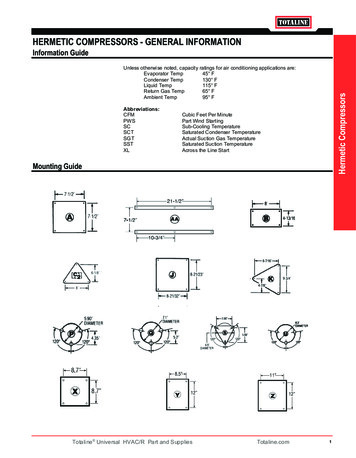
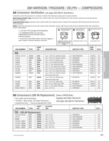
QT/QTS Series50161-108, January 2013Quincy Compressor103501 Wismann Lane, Quincy Ill. - 62305-3116Fig. 3-13 Phase Magnetic Motor Starter With Automatic Start / Stop ControlWiring Schematic WP1744A (Rev. D)At Installation, the customer is to provide:Disconnect and branch circuit overcurrent protection and groundingbetween the power supply and the electrical control enclosure in accordance with the National Electrical Code (NEC), the Canadian ElectricalCode (CEC) and / or any local codes having precedence.Dashed lines represent wires supplied by others.All wires are red unless otherwise specified.CAUTION !Verify all wires are secureand fasteners are torquedbefore connecting power tothe unit.OverloadRelayContactorConnect incoming power linesat screw terminals L1, L2 & L3.Magnetic Starter
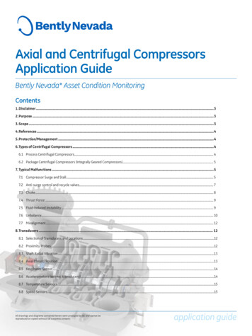
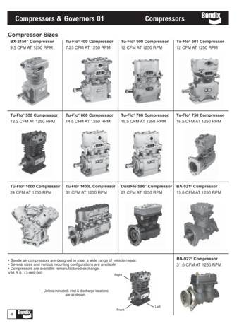
QT/QTS Series50161-108, January 2013Quincy Compressor113501 Wismann Lane, Quincy Ill. - 62305-3116Fig. 3-2Single Phase Magnetic Motor Starter With Automatic Start / Stop ControlWiring Schematic WP1744B (Rev. D)At Installation, the customer is to provide:Disconnect and branch circuit overcurrent protection and groundingbetween the power supply and the electrical control enclosure in accordance with the National Electrical Code (NEC), the Canadian ElectricalCode (CEC) and / or any local codes having precedence.Dashed lines represent wires supplied by others.All wires are red unless otherwise specified.OverloadRelayContactorVerify all wires are secureand fasteners are torquedbefore connecting power tothe unit.CAUTION !Connect incoming power linesat screw terminals L1 & L2.Magnetic Starter
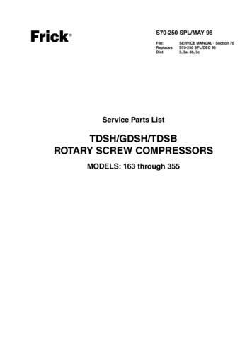
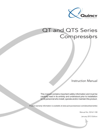
QT/QTS Series50161-108, January 2013Quincy Compressor123501 Wismann Lane, Quincy Ill. - 62305-3116Fig. 3-3Single Phase Combination Pressure Switch / Overload RelayWired to an 1800 RPM MotorConnection DiagramBranch circuit overcurrent protection and grounding between the power supplyand the pressure switch in accordance with the National Electrical Code (NEC),the Canadian Electrical Code (CEC) and / or any local codes having precedence.At Installation, the customer is to provide:CAUTION !Verify all wires are secureand fasteners are torquedbefore connecting power tothe unit.Connect incoming power linesat screw terminals L1 & L2.DO NOT FORCE!3. Re-install the small cover screws and tighten.To Re-install the Cover:1. Make sure the switch handle is in the “OFF”position (as shown).2. Carefully slide the cover over the pressureswitch.Pressure SwitchTo Remove the Cover:1. Turn the switch handle to “OFF” position.2. Remove small screws on side of the cover.3. Pull the cover away from the pressure switch.
QT/QTS Series50161-108, January 2013Quincy Compressor133501 Wismann Lane, Quincy Ill. - 62305-3116Fig. 3-4Single Phase Combination Pressure Switch / Overload RelayWired to a 3600 RPM MotorConnection DiagramBranch circuit overcurrent protection and grounding between the power supplyand the pressure switch in accordance with the National Electrical Code (NEC),the Canadian Electrical Code (CEC) and / or any local codes having precedence.At Installation, the customer is to provide:CAUTION !Verify all wires are secureand fasteners are torquedbefore connecting power tothe unit.Connect incoming power lines atscrew terminals labeled “LINE”.DO NOT FORCE!3. Re-install the small cover screws and tighten.To Re-install the Cover:1. Make sure the switch handle is in the “OFF”position (as shown).2. Carefully slide the cover over the pressureswitch.Pressure SwitchTo Remove the Cover:1. Turn the switch handle to “OFF” position.2. Remove small screws on front of the cover.3. Pull the cover away from the pressure switch.
Fig. 3-5Start / Stop ControlPiping Schematic WP1781BQT/QTS Series50161-108, January 2013Quincy Compressor143501 Wismann Lane, Quincy Ill. - 62305-3116
Fig. 3-6Continuous Run - Load / Unload ControlPiping Schematic WP1781CQT/QTS Series50161-108, January 2013Quincy Compressor153501 Wismann Lane, Quincy Ill. - 62305-3116
Fig. 3-7Dual Control with Pilot Valve UnloadingPiping Schematic WP1781AQT/QTS Series50161-108, January 2013Quincy Compressor163501 Wismann Lane, Quincy Ill. - 62305-3116
Fig. 3-8Dual Control with Solenoid Valve UnloadingPiping Schematic WP1781QT/QTS Series50161-108, January 2013Quincy Compressor173501 Wismann Lane, Quincy Ill. - 62305-3116
1.15, the overload relay setting must be adjusted to compensate. Contact yourQuincy distributor for assistance.Overload relays are designed to protect the motor from damagedue to motor overload. If the overload relay trips persistently, DONOT CONTINUE TO PUSH THE RESET BUTTON! Contact your local Quincy distributor for assistance.CAUTION !MountingWARNING !The compressor unit must be removed from the shipping skid priorto operation.Properly mounting Quincy compressor units is crucialto the safe operation and longevity of the equipment.The installation requires a flat and level concretefloor or pad (for mobile units see Mounting MobileUnits). Satisfactory results can usually be obtained bymounting horizontal tank units on vibration isolatingpads available from your local Quincy distributor. Allvertical tank units must be anchored! Refer toFig. 3-9, Isolator Installation for Unanchored orAnchored Receivers. Quincy recommends that allvertical tank units be mounted as indicated withoutisolators.1/2” locknut1/2” flat washer1/2” locknut1/2” flat washertank foottank footisolator backing plate1/2” locknutisolator backing plate1/2” flat washerisolatortank foot1/2” x 2” bolt1/2” floor studisolatorHORIZONTAL TANK UNITSUNANCHORED(provided by customer)HORIZONTAL TANK UNITSANCHORED1/2” floor stud(provided by customer)VERTICAL TANK UNITSANCHOREDFig. 3-9 Isolator Installation forUnanchored or Anchored ReceiversState or local codes may mandate that the compressor be bolted to the floor. In this case the unit mustbe leveled and bolted making absolutely certain thefeet are not stressed in any manner. Leave the locknut loose! Uneven feetdrawn tightly to the concrete pad will cause severe vibrations resulting incracked welds or fatigue failure. The customer is responsible for pro viding asuitable foundation & isolator mounting where necessary.Mounting Mobile UnitsGas engine driven compressors mounted to truck beds should be fas tenedin such a way so as not to create any stress to the air receiver tank. Truckbeds, characteristically, have a tendency to flex and could cause damage tothe receiver tank if the tank is fastened directly to the truck bed. It is theuser’s responsibility to provide an adequate means of fas tening the unit inthese applica tions.CAUTION !Do not operate this compressor more than 15 off level or move itwhile it is operating.System componentsEfficiency and safety are the primary concerns when sel
The fan blades force ambient air across cylinder head and intercooler fins to cool the compressor. These compressors are designed to be operated with the compressor sheave turning in a counterclockwise rotation (as viewed "tummy to the sheave"). Principles of Dryers & Filters Moisture occurs naturally in air lines as a result of compression.