Transcription
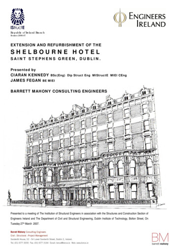
Republic of Ireland BranchSession 2006-07EXTENSION AND REFURBISHMENT OF THESHELBOURNE HOTELSAINT STEPHENS GREEN, DUBLIN.Presented byCIARÁN KENNEDY BSc(Eng) Dip Struct Eng MIStructE MIEI CEngJAMES FEGANBE MIEIBARRETT MAHONY CONSULTING ENGINEERSPresented to a meeting of The Institution of Structural Engineers in association with the Structures and Construction Section ofEngineers Ireland and The Department of Civil and Structural Engineering, Dublin Institute of Technology, Bolton Street, OnTuesday 27th March 2007.
The Shelbourne Hotel, Saint StephensGreen has been a Landmarkestablishment in Dublin for over 175years. The hotel has recently beenrefurbished and enhanced by theadditional of a substantial extension.This paper documents the renovationworks to the protected structure andthe construction of the new edialworksperformed to the heritage wings aredescribed and an overview given ofthe new build element.It is reputed that the hotel wasacquired by William Jury and CharlesCotton in 1865 and was completelyrebuilt in the present Victorian manner.The new hotel was designed byarchitect John McCurdy and was fittedout with all the latest Victoriancomforts of that time. The originalbuilding has undergone severalalterations and remodelling over theyears in order to continue serving asan operating hotel.The hotel staged one of the definingmoments of Irish history in 1922 as thelocation for the drafting of The IrishConstitution under the chairmanship ofMichael Collins in what is retained asthe constitution room.More recent acquisitions includednumber 33 and 34 St Stephens Greenwhich were in use as Hostel buildingsup to the 1960s.1.1.1Historic MapsA study of the historic maps of Dublinstarts with Speeds map of 1610 whichshows a city layout resembling Dublininner city of today centred aroundChristchurch Cathedral and DublinCastle. There are no buildings of anysignificance noted in the area nowoccupied by the Shelbourne hotel.Figure 11.1HistoricalBackgroundThe Shelbourne Hotel, one of Dublin’sbest known establishments, occupieswhat is no doubt one of the finestlocations in Dublin. Facing onto StStephens Green with a view over thepark and out to the Dublin Mountains.It has for many years held thereputation of being the finest hotel inthe city.The Hotel was founded in 1824 byMartin Burke when the three houses27, 28 & 29 were joined together andknown as ‘Burkes Hotel’. This quicklybecame the most fashionable place tostay in Dublin at the time. The threehouses that comprised the originalstructure replaced a much olderresidence known as Carey Housewhich was constructed in the 18thCentury .ThehotelwasrenamedtheShelbourne Hotel in recognition of thefact that the Earl of Shelbourne onceresided in Carey House. The use ofthis title and the association with theearl undoubtedly added prestige, aprestige that has been maintained untilthe present day.De Gomme’s map of 1673 shows anamount of development in the 60 yearssince Speed. St. Stephens Green isclearly defined, neither MolesworthStreet or Kildare Street are shown.Charles Brookings map of 1728 showsthe Green as walled with the tree linedpromenade around the periphery. Onthe map, the north side of the Green isshown as fully built and all the streetinfrastructure,includingDawsonStreet, Molesworth Street and KildareStreet are shown. However, KildareStreet does not penetrate the buildingsto intersect with the Green.Figure 2 John Rocques Map 1756Ordnance Survey Sheet 18-68Revised 1908, Published 1909 showsthe footprint of the buildings to St.Stephens Green with the bay windowsand is noted as Shelbourne Hotel. Atthe rear, almost the entire site hasbeen covered with buildings includingthe lane.1.2Existing Site Layout1.2.1SiteandLayoutBuildingA plan of the existing elements prior tothe recent alteration and extension isshown in figure 3 and an aerial viewcontained in photographs 1 & 2, themain components are listed as follows;1.TheMcCurdyWing,StStephens Green Wing WestSt Stephens Green Wing EastKildare WingReception Block1960’s WingBallroomPool and Leisure CentreAdmin Annex BuildingsBoiler House Stores & PlantRooms1990s Block (above 7, Leisure)The Shelbourne Garage2.3.4.5.6.7.8.9.10.11.Twenty eight years following BrookingJohn Rocques map of 1756 showsconsiderablechangealongtheNorthside of the Green. Kildare Streethas penetrated the buildings tointersect with the GreenOrdnance Survey Sheet 27-Surveyedin 1838 and published 1847 is the firstof the ‘modern’ maps available. Itshows No’s 27, 28, 29, 30 and 31 StStephen’s Green as a terrace, butdoes not note them as the ShelbourneHotel. No 27 is the corner building andreturns down Kildare Street. Theoutbuildings and garden layout areclearly shown.KILDARE STREET1 IntroductionNORTH ST. STEPHEN'S GREENFigure 3 Key Plan2
1.2.2Existing Structures1.2.2.1 Heritage WingsThese buildings occupy numbers 27 to34 St Stephens Green and the Kildarewing buildings (ie nos 1, 2 and 3 aslisted above).pool and further bedrooms in the northeastern side of the site linking inbehind number 34 St. his block comprises a reinforcedconcrete frame up to mezzanine levelsupporting a steel cantilever structuresupporting prefabricated bedroompods ZANINE20.801st1.2.2.4Annex buildingsThese were of traditional .1.2.3Figure 4The heritage wings are generally oftraditional construction comprising loadbearing masonry elements supportingtimber floors. Cut timber roofs arefinished in slate. These blockscomprise elements which have been dinternaldimensions reflect these past layouts.These buildings are reported to havebeen reconstructed around 1850 andare described in further detail later inthis paper.ExistingInterconnectionsThe point of interconnection betweenthe different blocks varies at eachlevel. The floor to ceiling heights varyfrom block to block and from floor tofloor within individual blocks. Thisresults in a wide variance inrelationships between floorsThe St. Stephens Green Block hasfloors at basement ground, first,second, third, fourth and fifth with apitched roof above. The ground floorlevel is within 400mm of the publicfootpath. There is a close relationshipbetween the ground level of theShelbourne Wing / Kildare Wing andreception area. The ground floor of theSt Stephens Green Wing East frontingthe leisure centre are accessed offsteps from St Stephen’s Green publicfootpath and are 600-800mm abovethe level of the Mc Curdy Block, to thewest.1960s buildingAs the term suggests this block wasconstructed during extension andredevelopment works carried outduring the 1960’s. The structurecomprises a reinforced concrete frameconsisting of reinforced concrete wallsand piers running north to south with acantilevered structure overhead.The building is eight storeys aboveground level namely ground, upperballroom, mezzanine second, third andonto sixth relating to some degree withthe heritage wing floors but albeitloosely. An existing shear wall existson the north end gable providingstructural stability in the narrower east/ west direction.1.2.2.31990’s buildingA project to increase accommodationwas embarked upon in the early1990’s under the direction of theowners and occupiers at that time.This element included the constructionof the leisure centre, gym, swimmingGROUND13.8011.10BASEMENTFigure 6 Section Through St Stephens and Rear WingThis floor numbering system maintainsthe relationship between the upperfloors. This system has been appliedthroughout all the blocks from the1960’s refurbishment, 1990’s andthrough to the present day alterations.This relationship is shown in sectionon figure 6 above.Photograph 2 Ariel View From Rear2 DesignDevelopmentOne of the main design objectives wastoenhancetheexistingaccommodation and increase thenumber of bedrooms, conference andcommercial accommodation. Coupledwith this the opportunity was taken toimprove the circulation throughout thehotel with particular regard tohorizontal travel to achieve universalaccess and more efficient housekeeping trolley routes.Figure 51.2.2.2FIRST15.08Photograph 1 Ariel View From FrontThe St. Stephens Green wing groundand first floor levels provide some ofthe most precious public space. Thefloor to ceiling height of these areasare very generous, the first floor levelof the Kildare wing is lower than thefirst floor level of the St StephensGreen Wing. What would normally betermed the third floor level of theKildare wing relates very close to thesecond level of the St Stephens Greenand is referred to as the second floorwith the level below referred to as themezzanine level.Photograph 3 Internal Steps3
As part of the accommodationreconfiguration the previous use of thebasementforbackofhouseoccupations were identified as areasthat could be relocated to createpremier space fronting onto the publicareas. The floor and floor to ceilingheights in these areas variedconsiderably throughout, in additionthe areas were subdivided by manywalls.An aesthetic gain was sought toremove in as far as possible largeservices items from the roof level toclean up the roof line. The bulk of thewater storage capacity for the existinghotel was provided for in various waterstorage tanks such as the oneillustrated in photograph 4 supportedoff steel beams spanning betweenchimney stacks over the Kildare wing.floor of the 1960’s wing whereas theeast wing relates to the 1990’s block.There are ramps incorporated betweenthe Kildare corridor and West wing toeliminate steps.Ramps are incorporated between thewest and east components of the newextension to maintain level access.Due to the fluctuation in therelationship, the West wing starts offlower than the east wing however thesituation is reversed once we reachthe upper levels. In addition to ramps adouble aspect lift is provided in thenew build coinciding with the leveltransition.A new lift shaft located in the newreception area now serves the newextension, Kildare Wing, 1960’s,1990’s Wing. The remaining areas ofthe St Stephens and McCurdy wingsare accessed off other lifts that areretained. Interconnection betweenthese levels can be found at basementand other ‘back of house’ areas.2.2AccommodationThe accommodation schedule for theexisting building pre development andpost extension is summarised in table1 below.Photograph 4 Roof Top Water TanksPhotograph 52.1Proposed Site Layout& CirculationThenavigabilitywasseverelyrestricted by the widespread presenceof steps. The design brief was tocorrect and alter this situation toimprove general access and allow amore efficient circulation.The design intention was to eliminatethe annex buildings and provide a newextension which would increaseaccommodation and provide a linkbetween the three rear projectingwings, namely the Kildare, 1960s and1990s. The new extension has beendesigned to incorporate changes inlevel and aid the transition betweenthe aforementioned blocks. The newbuild extension is divided into twoparts, the East and West wings. Thewest wing is generally level with the2.3Planning applicationA planning application was lodged inDecember 2002 for the extension andredevelopmentworksandwassubsequently granted permission.Further planning applications and partV declarations for alterations to theprotected structure were submittedduring the course of the works asdesigns were further developed andopportunitiesrealised.Beingaprotected structure the planningapplications included alterations to theexisting building to allow for theinstallation of services to meet withmodern hotel requirements.Figure 7Theinitialplanningapplicationincluded for the installation of a firesprinkler system in the protectedstructure and included details for floorstrengthening works, alterations andnotching to allow other serviceinstallations.2.4Fire Safety CertificateThe overall height of the proposedextension called for a 90 minute firerating. The fire strategy includes theuse of protected corridors and stairshafts including the use of a firefighting lift shaft. These protectiveelements are designed to have a 120minute fire rating.The existing building renovations andreconfiguration have been carried outto achieve a 60 minute fire rating.Automatic Fire doors and smokeextract form part of the fire strategy toprotect the occupants in the heritagewings. In addition, although no benefitis accepted in terms of fire protectionby the Local Authority, the building hadto comply with the operators own firestrategy and is protected in its entiretyby sprinklers.This building is considered the first inthe country of such heritage value tobe protected by the introduction of asprinkler system.Schedule of AccommodationReconfigured Heritage AreasGround Level Public spaceUpper level Bedrooms & Conference spaceTotal Heritage Floor AreaHeritage Bedroom Count(Count excludes annex buildings and demolitions)Retained Modern Blocks 1990 & 1960s1960 1st to 6th floor1990 Excluding Leisure Club1960 & 1990 Room CountNew Build AreasNew Extension Double level BasementNew Ground Level ExtensionNew Extension Floor Area above GroundNew Roof / Plant SpaceNew Build Bedroom Count (plus 6 junction rooms)New Build Total Floor AreaBallroomPrevious BallroomRevised BallroomNew Basement Below BallroomTotal Bedroom CountTotal Floor AreaTable 1 Schedule of AccommodationPreviousNew1,950 m26,720 m28,670 m212083950 m2860 m270 -770 m21,275 m25,440 m2680 m21148,165 m2350 m2190455 m2350 m226719,450 m24
The bridge was offered support by theannex buildings at one end andintermediately by a transfer beamspanning off a chimney stack andmasonry pier built off the leech suitewalls. Demolition of the annex buildingwas halted once progress reacheddown to the bridge level until thebridge could be removed. Demolitionof the enclosure was performed byhand off a scaffold platform until themain steel beams were exposed. Thebeams were then craned out anddemolition of the annex continued.3 Construction3.1Site investigationThe constraints imposed by theoperating hotel and the near fullyoccupied site footprint limited thescope of the initial site investigation. Agood knowledge of the anticipatedground conditions was establishedfrom the review of investigations ofneighbouring sites that the Practicehad been involved with and from astudy of borehole logs recorded fromthe 1990s development.To ascertain the conclusions made bythese studies two boreholes wereperformed as part of early site works tothe rear laneway around the time thatthe hotel was winding down operationsin March 2005. Boreholes werechosen as the most appropriate meansof investigation since they limited theextent of interruption and the depths ofthe proposed formation were wellbelow the reach of trial pits. Theresults of this investigation validatedthe earlier design assumptions andprovided additional information withregard to ground water characteristics.These boreholes were taken from aground level of c.10.8mAOD. Recordsof these bore holes are shown in figure8 and are generalised as follows;varying levels of fill over a brownboulder clay/ gravel with an allowable2bearingpressureof200kN/mExtending to a depth of approximately5m where Black boulder clay waspresent. The water level was found tobe approximately 2.5 below the rearyard at a level of 9.4mAOD. Refusal,suspected rock, was found at 8.2mbelow the ground tingHeritagewings.Site Commencementand DecantingFigure 8 Borehole RecordDecanting and storage of items, manyof which are of historic significancewas included as part of the contractorsbrief. Fixtures fittings and furniturewerecategorised,recorded,photographed and packaged forremovaltodesignatedstoragefacilities.Photograph 6 Annex Bridge LinkThe barber shop which was located inthe centre of the site at basement levelwasunderseparatetenancy.Accommodation works were enactedto create a new barber shop located atthe front of the building accessed byan external stairs via the front lightwell.This fit-out and changeover wascompleted within a two week periodand remained the only area occupiedby anyone other than the contractor forthe full duration of the contract.The reinforced concrete structure thatonce housed the store rooms andplant rooms at the rear of the ballroomwas demolished using breakingequipment. The structure was formedwith several cantilever slabs andcorbelled walls which required carefulplanningandsequencing.Thecompletion of this initial phase ofdemolitions made way for thecommencement of the new buildworks.Contractoraccommodationandcompound was provided in theShelbourne garage located on the farside of Kildare Street.A conservation inventory of all fittingsand items in the Annex buildings to bedemolished was required as part of theplanningconditions.Fromthisinventory items that were to besalvaged were identified and a softstrip of these items was then carriedout.Photograph 73.2.33.2.2DemolitionsSite activity commenced in March2005, the original intention was tocomplete the project in several phasesallowing partial occupation and acontinuance of the hotel operations.The initial demolition phase concernedthe annex buildings, constructed oftraditional masonry construction andthe store and electrical plant room ofmass concrete construction.Phasing stages were investigated anda strategy developed. A change inownership of the hotel and operatorsgave an opportunity to re-examine thisapproach. Tackling the works in asingle phase would allow the project tobe completed in a shorter time frameand eliminate the potential difficultiesboth to the contractor and to the hoteloperators with regard to building in alive hotel environment.Demolition of the annex buildings wasperformed by hand off access scaffold.Interconnection between the annexbuildings and the St Stephens Greenwas previously provided at basement,ground and first level. A furtherrdconnection existed at the 3 floor viaan enclosed foot bridge spanning 20mover the historic Leech suite.Floor Assessment andRepairsThe initial assessment of the structurewas restricted by the live hotelenvironment. Limited opening upworks were carried out on a piecemealbasis where entry into unoccupiedhotel bedrooms was permitted. Thisgave an insight into the structural form.Despite the absence of major openingup works the presence of significantsloping and deflecting floors causedsome degree of concern. In someinstances the slopes were measuredover 150mm across the width of atypical four metre wide room.5
Slopes were prevalent in corridorsparticularly at the first floor level.Photograph 10 illustrate the findingsbefore work commenced on site. Thepresence of the laundry trolley at thedownward site is not coincidental. Theslopes had been an issue with thehotel maintenance staff to the extentthat in the past furniture legs had to bealtered to achieve an even seating onsome of the floor surfaces.depth and location of known notcheswere input and the joist capacitycalculated at 100mm intervals alongthe length and compared with thetheoretical stresses. An allowablebending stress of 9.5 N/mm² waspermitted based on the age of thetimbers. Joists were checked for shearand deflection in the same manner.beam was insufficient in terms oftheoreticalstructuralcapacity,displayed signs of distress andpresented an obstacle for the routingof services. The beam was found to besupported off the timber partitionseach side. A similar structural systemwas noted at every level above.Areas were categorised as beingcompliant or otherwise. Generallythere was a consistent relationshipbetween the overstressed joists andthe areas of excessive deflections.Survey Drawings were then compiledto record joist sizes, centres, ph 12 Deflecting Timber BeamPhotograph 8An extensive series of opening upworks was embarked upon at an earlysite stage. The initial findings of theseopening up works revealed timber joistof varying depths thickness andcentres. Various spans lengths anddirections with or without intermediatesupports. The presence of notchesfrom previous alterations at mid span,additional loads from timber partitionsand the transfer of loads from upperlevels.Photograph 11 Corrected SlopeIn parallel with this it was proposed tocarry out mock up rooms in theheritage wings to tease out anypotential difficulties at an early stage.One of these mock-up rooms was tobe located in the Kildare wing atmezzanine level and the second in theSt Stephens Green wing at third floor.These mock up rooms were intendedto help identify service routes. Bycoincidence the mock up roomschosen coincided with areas wheresome of the most interesting structuralconditions existed.3.2.4Mock-up RoomsPhotograph 93.2.4.1 The Kildare Wing MockUpThe previous room 216 at mezzaninelevel in the Kildare wing fronting ontoKildare street was selected to bestrepresent the proposals for that wing.The mock up rooms were to include allworks which would be intrusive on thestructure including service wiring andpiping installations.Photograph 10 Sloping CorridorA spreadsheet was prepared to takeintoconsiderationtherelevantparameters and calculate the bendingand shear stresses experienced by thejoists. Records of the surface finishessuch as leat and plaster ceilings etc.were used to determine the dead loadweight. An allowance of 2.5 kN/m² wasmade for bedroom live loads and4.0kN/m² for corridor UDL loading. TheFloor boards were lifted to identifyservice routes and investigate thepossibility of reusing the existingroutes. The joists in this room ran fromthe external wall towards the internalcorridor wall and measured 35 x225mm dp. When the full extent ofboards were lifted it was found that theboards were supported intermediatelybyatimberbeamrunningperpendicular to the joists carryingjoists spanning c3.5m each side. ThisThe initial survey drawings showedtwo columns located in the officespace immediately below at first floorlevel which was in turn directly overthe Shelbourne Bar.This line ofstructure coincided with the line of thewalls separating bedrooms abovewhich continued up to roof level fivestoreys above. This was on thepartition line that offered support to thetimber beams described above. Adesire was expressed to remove thecolumns as they presented difficultiesin utilising the space efficiently.Opening up works revealed that eachof the so called columns consisted oftwo 6” x 2” timber members nailedtogether and connected by nailing inthrough the side of a single joist whichspanned 7 metres at the first floorlevel. The members appear to havebeen a remnant from an old partition,more than likely intended to spanbetween supporting walls by trussaction. There was evidence ofdiagonal members which had been cutto allow for a past reconfiguration.Alternatively a support wall could havebeen present from ground level whichwas removed to make way for theShelbourne Bar. Either way significantdeflection was evident in this area andno clear load path was obvious. Thecapacity of the partition above wasdetermined to be adequate for thetransfer of vertical forces, however thedistribution of the load back to thesupport point could not be justified.This load bearing line was temporarilypropped back to the basement level toallow work continue advance in themock up room.Steel beams were introduced betweenthe floor joists at every level spanningbetween the front and internal walls.These beams carried intermediatebeams arranged perpendicular andproviding an intermediate support pointto the retained timber joists. In some6
locationsitwasfoundmoremanageable to adopt a ‘like for like’replacement strategy.improvement but were somewhatdistorted by a reversal in the trafficflow around St Stephens green, analteration that increased the trafficcountonKildareStreetandcompounded difficulties in terms of siteaccess, scaffolding and deliveries.3.2.4.2Photograph 13Sloping floors on the upper levelswhere corrected by the introduction offirring pieces of up to 120mm deep.Firrings were cut on site to suit theslope of individual joists. It was notedduring the course of these works thatprevious firing pieces had beenintroduced as a corrective measure butthe cause of deflection had not beentackled and obviously continued since.The new firring pieces were screweddown into the top of the existing joists.The additional depth over the parentjoistprovidedameanstoaccommodate service routes.The span of the floor joists above theShelbourne Bar were very long at 7.5metres. They were found to beinsufficient by theoretical calculation.Excessive deflection at 160mm in thecentre was a symptom of this. Thefloor above the Shelbourne Bar waspropped to provide temporary supportand the floor was strengthened by theintroduction of new steel beamsrunning parallel to the existing joistssupporting perpendicular beams at midspan, laid above the joists andconcealed within the depth ofcorrective firring pieces. Steel strapshung from these cross beams carryingthe joists beneath and hencestrengthening the floor. All this workwas performed without incurring anydamage to the decorative plasterceiling presented in the ShelbourneBar below.Generally the condition of the timbersbearing into the front brick wall werefound to be dry and in good condition.In addition to the structural works,mechanical and electrical fit out andfinishes a secondary glazing systemwas installed which formed part of theacousticenhancementofthebedrooms against noise from the busystreet below. The worst culprit beingheavy vehicles, buses in particularpulling off from the traffic lights. Theresults of the acoustic tests werecompared to base readings taken inadvance of the works commencing.The readings showed a markedSt StephensMock UpGreenThe room selected at the front of thethird floor on St Stephens green wasalso found to have joists spanningfront to back supported off the frontand corridor walls. A timber beam wasfound to be present offering supporthalfway along the joist span. Howeverin this case the supporting beamconsisted of a 175 x 100 joist spanning4.5m and carrying joists spanningalmost 4m each side. The ‘beam’ alsocarried the weight of en-suite partywalls built off the floor as part of a refitin the 1980s. This beam could not bejustified theoretically and even by theleast conservative of methods onlyoffered 8% of the required bendingresistance for the loading applied atthat level.Photograph 14 St Stephens Wing Deflected BeamThis beam was carried by the timberpartitions each side, the partitions fromthe third floor level did not align withthose below and were inset on thebeam by 500mm, meaning that thebeam also acted as a transferstructure.with timbers. The ends of the existingjoists were supported off steel joisthangers as shown in photograph 15. Afurther lift of post was welded to thesteel beam which now acted as a newtransfer element and carried a similarbeam at fourth floor level. All exposedsteelwork was fire protected to achieve60 minutes rating.Photograph 15 Reinstated Support3.2.5BedroomReconfigurationsThe existing bedrooms throughout theheritageblockshavebeenreconfigured to make better use of theavailablespaceandprovideaccommodation more suitable for afive star establishment.Thisprocessrequiredcarefulassessment of the existing layouts byall disciplines of the design team andidentification of the options forreconfiguration. From a structural viewpoint this involved assessing thefunction of all walls and identifyingthose that could be either sensiblyaltered or removed.The result of this exercise has been toincrease the suite numbers in theheritage rooms but to reduce theoverall bedroom count in these blocksfrom 120 to 83 No.After further significant opening upworks it was found that the wall belowwhich carried this beam was in turnsupported off a steel girder at first floorlevel.A route was identified that allowed theinsertion of a new steel post downthrough the timber wall with minimumdisturbance of the decorative cornicingor other important aesthetic finishesand fabric of the building. The timberjoists were propped off two floorsbelow and the beam at third floor levelwas removed, the ends of the joiststhat once met the timber were trimmedback and a new steel beam offered inits place supported off the new steelpost.A wall plate was fixed to the top of thesteel beam and the webs were packedPhotograph 163.2.6The Horseshoe BarThe Horseshoe Bar remains asintended by architect Sam Stephensonas part of the 1957 reworking.The floor joists at the first floor levelrear section directly over theHorseshoe Bar were found to spanfrom the front corridor wall to the rearwall of the St. Stephens Green, a span7
of 7.6 metres, picking up the rearcorridor wall as a point loadapproximately 2.5 metres from thesupport end. This partition wall alsotransferred load from the joists aboveand is shown in figure 9.The joist sizes in this area measured9” x 2” (225 x 44mm) and werepositioned at 1’ (300mm) centres.Significant defection was recorded inthe bedrooms and particularly thecorridors at first floor level. The joistsalso served as the support to theceiling of the Horseshoe Bar, regardedas one of the most sacrosanct areas ofthe hotel. Any attempt to enhancestrengthen or repair these joists wasnot permitted to have any impact onthis room.from the first floor.A horizontal rail comprised of an 80x80RHS was laid on top the joists at firstfloor. Metal straps were hung from theSHS and connected to the joists usingsingle sided shear tooth connectors.The horizontal rail was then hung fromthe truss overhead via 60x60 SHS tiemembers providing an intermediatesupport to the first floor level joists.Photograph 17 TrussThe horizontal rail was concealedwithin the depth of what would becomethe corrected floor level. New firingpieces were measured, cut andoverlaid over the already deflectedjoi
chimney stacks over the Kildare wing. 2.4 Photograph 4 Roof Top Water Tanks app 4 Schedule of Accommodation Previous New Reconfigured Heritagerestricted b Areas Ground Level Public space 1,950 m2 Upper level Bedrooms & Conference space 6,720 m2 Total Heritage Floor Area 8,670 m2 Heritage Bedroom Count 120 83
