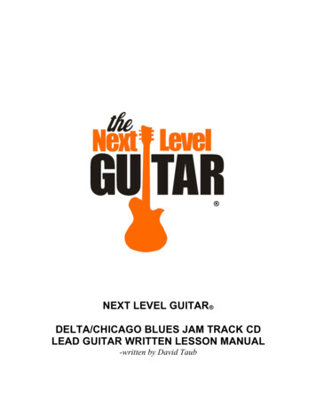
Transcription
Multi-function track recording carsAn objective basis for decision-making makes it possible to set up and implementa sustainable maintenance strategy. Multi-function recording vehicles helpto further improve the safety, cost-effectiveness and availability of the railwayinfrastructure.The railway companies are responsible forthe assurance of reliable rail infrastructurethat meets the needs of the customer, aswell as safe, cost-efficient and punctual operation of the rail services. The main taskof the infrastructure operator is to furtherimprove the safety, cost-effectiveness andavailability despite constantly rising volumes of traffic. Measured data provide anobjective basis for decision-making. Nowadays these basic figures are provided to alarge percentage by track recording cars.Plasser & Theurer is aware of the significance of this and can offer its high competence and experience in finding the verybest solutions for the future.A specific feature of railway infrastructureis the long service life of the track components. However, the service life is onlyachieved based on a suitable design of thetrack and appropriate maintenance. Clearbases for decision-making must be drawnup by a coordinated matrix of safety andquality figures. Maintenance strategies aredeveloped on this basis that makes it possible to manage the track assets over along period. Without comprehensible foundations it is very difficult to obtain the necessary funds for maintenance and renewal.The infrastructure operators have recognised this and therefore particularly overthe past years there has been a change inattitude towards track recording cars. Trackrecording cars are no longer seen purelyas a safety instrument but provide, in thebroadest sense, the means to take theright action at the right time. The change inthe importance of the track recording carsand the new technological possibilities inrecording technology – and here particularlyin video monitoring – have led to strongtechnological progress in recent years. Inthe light of this, Plasser & Theurer offerstrack recording cars with non-contact recording technology and video monitoringoptions for various sectors of the railwayinfrastructure (Fig. 1).1 Principlesits main purpose is focussed on the prevention and elimination of faults.The change in the perception of track recording cars has also been taken into account in international standardisation. Forexample the European standard EN 13848no longer defines any limit values for thevarious measuring signals. Instead it defines intervention limits that enable theuser to plan his maintenance schedule ingood time and well in advance.The acceptance of track recording cars haschanged dramatically in recent years. Originally, the most important function of a trackrecording car was to detect and localisetrouble spots in the track. The focus wasplaced on finding the anomalies and not oneliminating them. In many instances, therole of the track recording cars had a negative image.The intervention limits are described according to EN 13848-5 in three stages. Theresulting course of action to be taken whenthe signals are overstepped can be seenfrom their designation:Many railways have introduced a reversal ofthat trend. Track recording cars are used tooptimise visual inspection and the measuring results are used as a basis for decisionmaking for sustainable asset management.Early detection of anomalies relevant tosafety is also the function of the track recording car. However, with consistent useApart from this fundamental change in attitude, a trend towards the incorporationof new sources of information is also apparent. The railway administrations are increasingly setting store by video monitoringto reduce visual inspection on site. Over thepast years the requirement that measuringsignals always have to be reproducible has Stage 1: Alert Limit Stage 2: Intervention Limit Stage 3: Immediate Action LimitDr.-Ing. Dr. techn.Florian AuerMarketingPlasser & Theurer, Viennaflorian.auer@plassertheurer.com32RTR 3 4/2013Fig. 1: Off-board computer screen showing synchronised video and track data
Multi-function track recording cars nalso been softened. The highest demandson the reproducibility are placed on the classic track parameters such as track gaugeand twist, i.e. in various vehicle compositions and speed ranges the measuring systems must always supply the same result.At the same time, the importance of nonreproducible measuring signals such as theaxle box acceleration and pantograph acceleration is increasing. Acceleration peaksare an indicator of a possible trouble spoteven though the causes can often not bededuced from this.The example of Austrian Federal Railways(ÖBB) shows the trend reversal to fault prevention very clearly. In 2000 around 80 %of the permanent way decisions were to alarge extent based on the experience of thelocal district inspectors, but in 2010 thisfigure had dropped to only about 20 %. Theremaining 80 % were made on the basis ofthe results produced by various track recording cars. It did not happen by chancethat in recent years there was a reductionof rail breakage frequency and fewer temporary speed restrictions (Fig. 2).2 RequirementsThe railway infrastructure system consistsof various subsystems such as the trackand catenary, the control and signalling systems, the power system and other areas.To ensure as few operational hindrancesas possible, it is advisable to carry out themeasurement of parameters important forthe various maintenance operations simultaneously using one and the same track recording car. Moreover, this combined measurement offers the opportunity to performcorrelations between different track defectsand identify any possible connections ormutual influences. The costs for the operation of a multi-function track recording carare the same irrespective of whether oneor several parameters are measured. Thecost-efficiency of the track recording carrises with the number of parameters measured per run.Fig. 2: The influence of recording technology on maintenance performed on ÖBB rose sharply inthe last 10 yearschronised display of all measuring signalsin the off-board analysis software.3 PhilosophyHigh demands are placed on quality andavailability when selecting the measuringsystems. Plasser & Theurer's philosophy isas follows: only measuring systems with the highest accuracy and availability can providesupport for planning maintenance. Measured data and exception reportsmust be retrievable immediately. Onlythis can eliminate the risk of derailments. The latest and most up-to-date measuring systems on the market are incorporated. The track is regarded as a system. Measurements of the overhead line systemand the track structure can be analysedin a combined way. The focus is laid on quality and availability, and then on the price.4 Range of productsPlasser & Theurer offers a comprehensiveselection of basic vehicles. A clear rangeof available and combinable measuring andrecording systems are on offer. These options make it easy to select the right vehicle with suitable measuring equipment.Common to all models is the high-qualitymechanical engineering in conjunction withthe latest measuring technology (Fig. 3).For measuring, recording and analysis ofthe track geometry, the standard equipmentof every track recording car is the track geometry measuring system. This consists ofan inertial navigational measuring systemwith integrated GPS positioning and a dualoptical gauge measuring system. Track geometry faults with wavelengths up to 200 mcan be recorded, regardless of the measuring speed.The choice of the ideal track recording cardepends on the technical and commercialrequirements in coordination with userorientated equipment. Vehicle design andfittings are carried out in proven Plasser &A basic requirement to be met by the trackrecording cars is the on-line processing ofthe signals and information.Work to be done on-board during the measuring run: produce measuring graphs, supply exception reports (km, GPS), calculate track quality indicators (TQI‘s)and draw up line routing parameters.The design of the Plasser & Theurer onboard and off-board analysis systems isvery versatile and allows simultaneousmeasurement and analysis of the parameters directly in the track recording car. Another standard feature is the location-syn-Fig. 3: Plasser & Theurer offers a standardised selection of track recording carsRTR 3 4/201333
n Multi-function track recording carsTheurer quality. These series-built vehiclesalso meet the safety requirements specified for rail traffic. Mainly standardised construction elements are utilised for designand construction.All vehicles are fitted with low-emission diesel engines and two 2-axle bogies and witheither one or both bogies driven depending on the machine model. The measuringsystems can be mounted on either of thebogies.The bogies utilised are a Plasser & Theurerdevelopment and were designed speciallyfor heavy axle loads and speeds of up to200 km/h. The engine outputs range from190 kW on the EM 30 D weighing 21 metrictons to a total engine output of 1200 kW onthe EM 160 weighing 80 metric tons. Selfpropelled machines offer independenceand flexibility in operation.All Plasser & Theurer track recording carscan of course be placed in train consists.For special track situations, the vehiclescan also be designed in narrow gauge orbroad gauge. Diesel-electric generator setsprovide the power supply on board; an uninterruptible power supply unit is installed additionally to protect the measuring and dataprocessing systems. To gain space and atthe same time lower axle loads, large vehicles can be designed in two sections as"tandem vehicles" (EM140T und EM160T).These vehicles can also travel on commuterrailway systems and secondary lines withlow permissible axle loads and the entirenetwork can be measured using one trackrecording car. For example, three track recording cars built by Plasser & Theurer arein operation in New York City.5 Criteria when selecting a trackrecording carThe following main criteria have an influence on the choice of track recording car: Type and number of measuring systems Number of workplaces General space requirements Measuring speed Staff requirements Room layoutThe standard track geometry measuringsystem forms the basic equipment – allother installable measuring systems and/or video recording units and combinationsof these systems depend upon the size ofthe vehicle and the achievable space forthe computers and analysis units.At each of the evaluation terminals themeasured data can be retrieved, displayedand printed out. However, an additional,separate workplace is required to operatethe ultrasonic rail flaw detection system.For the average quota of planned measuringruns, it is necessary to select a measuringspeed taking into account the length of thetrack network, volume of traffic on the lineand the track recording cars available. Theself-propelled track recording cars travel ata maximum speed of up to 160 km/h andup to 200 km/h when hauled.The vehicles are fitted with sound-insulated,air-conditioned cabins and driver’s controldesks for both directions of travel. Depending on the size of the vehicle, additionalfacilities can be installed such as: conference corner, kitchen unit, sleeping berths,washroom with shower and WC, workshop.In addition to the standard crew in the trackrecording car, there are regional track inspectors or other local staff on board formany operations. The space required is defined by the number of personnel. If the sizeof the network and the planned operationsrequire stays of several days for the crew onthe recording car, then other facilities andsleeping berths must be provided.The location of the drive engine has a greatinfluence on the room layout. For reasons ofspace and comfort, it is preferable to installthe engine below floor level. The choice ofa slightly larger vehicle (longer distance between pivots), which allows the engine to bemounted under floor, will provide a far moregenerous room layout. This allows moreworkplaces (Fig. 4) and measuring equipment to be incorporated and thus raisesthe cost-efficiency of each measuring run.6 Measuring and video systemsNot only in the field of vehicle design butalso in the measuring systems the customer has the option of choosing from a widerange of standardised and well-proven systems. A selection of these possible measuring systems can be seen in Table 1.The standard equipment of every Plasser& Theurer track recording car includes thenon-contacting track geometry measuringsystem with integrated GPS navigation andDual OGM optical gauge measurement tomeasure, record and analyse the track geometry.This system measures the following parameters: longitudinal profile of left and rightrail, alignment of left and right rail, trackgauge (dual measurement), cross level,twist, curvature and curve radius, gradientand position using GPS.The high-precision, maintenance-free trackgeometry measuring system is a leader inquality and availability. The results are usedprimarily for planning the tamping work.From the analysis of the longitudinal profilesignal, it is also possible to localise areaswith advanced ballast wear and areas withsubsoil problems.The latest laser and video camera technology is applied to measure the profile andwear condition of the rails. The linear transducer with laser transmitters and receivercameras are mounted on one bogie of thetrack recording car. The laser units are precisely temperature stabilised, eliminatingthe need to shield off ambient light fromthe measuring area on the rails. The receiver cameras capture full cross-sectional railprofiles from the base area to the top-of-railsurface. Rail wear data are used for planning rail exchange, the measuring signalsfor rail inclination and rail base distance aregood indicators for the condition of rail fasteners in tight track curves.It is also possible to issue the value of theequivalent conicity online. This value is anindicator for the lateral running behaviourof the vehicles. Austrian Federal Railwaysbegan early on to develop and implementtargeted counter-strategies. The statisticsshow a clear reduction in areas with increased conicity.Fig. 4: The trackrecording cars areideally equipped for theoperators and the users34RTR 3 4/2013Corrugation and axle box accelerationmeasuring systems are among the systemsmost used. Both are parameters neededfor planning rail grinding.Apart from this, it is mainly the ultrasonicrail flaw detection system, the tunnel clear-
Multi-function track recording cars nance measuring system, the driver’s viewvideo system and the track componentvideo monitoring system that are increasingly being ordered. The four systems aredescribed in detail in the following.6.1 Ultrasonic rail flaw detectionsystemThe ultrasonic rail flaw detection systemis used to detect internal rail flaws. Thesystem is mounted on a telescopic measuring axle and is suitable for speeds upto 60 km/h. The sixteen transducers thatmeasure one rail are located in two wheelprobes which are guided along the centreof the rail. A separate workplace insidethe track recording car is used to operatethe system and to analyse the ultrasonicsignals. The ultrasonic data are used togenerate a side profile of the actual rail(consolidated B scan video image). P atternrecognition software is used to identify andclassify the rail flaws. The measuring system supplies location and track information. Off-line multiple run comparison histograms can be created and analysed.A specially developed wheel probe designleads to highest availability and less waterconsumption. There is optimal lateral guidance of the wheel probes for better detection of vertical rail head cracks. The systemconsists of a fully integrated Windows operating system with redundant data acquisition and storage. There is continual furtherdevelopment in the field of pattern recognition and classification.Table 1: Overview of themeasuring systemsAbove all the following feature is important:the high-tech ultrasonic rail flaw detectionleads to an increase in operating reliability. Early detection of cracks originating atthe running edge (particularly relevant forthe rail flaws known as head checks) isachieved by specially inclined sensors(Fig. 5).Fig. 5: Modernultrasonic probe wheels(installed in rubberwheels) are wear-freeand have low waterconsumption6.2 Tunnel clearance measurementThe measuring system is designed forchecking the standard clearance gauge andalso the lateral and vertical distances tothe adjacent track axis and to station platforms. It consists of a rotating laser scanner mounted on one end of the recordingcar which measures the distance from thescanner to the track surroundings and tothe track bed. Measurements are taken upto 9,000 times per revolution with a rate ofup to 200 revolutions per second (Fig. 6).The measured data are stored lined-up withall other measuring data. The system isnow used increasingly for measuring overhead line (OHL) systems, as the results ofthe laser measurement can also be usedfor OHL position measurement.The system software simultaneously compares the measured data with up to threedifferent clearance envelopes in real time.Infringements are shown in the clearanceexception report. In curves, clearance profiles are automatically adjusted for vehicle-specific overhang using the curvaturemeasured by the track geometry measuring system. At the same time, the systemchecks the ballast distribution along thetrack. By simultaneous comparison of theactual ballast profile with up to three different ballast profiles, the software calculateswhether there is an excess or deficit of ballast on any given location and gives the respective quantities.The laser system presents no danger tothe human eye. It is eye safe and not influenced by ambient light.6.3 Driver’s view videoIt is useful to include the driver's view videofor a variety of analysis applications. Thefact is not surprising that the driver's viewvideo is extremely popular with the railwaysdespite its lack of complexity.This video system records images of thetrack, the track surroundings, and the catenary wire structures, as seen by the driverof the track recording vehicle (Fig. 7).OneRTR 3 4/201335
n Multi-function track recording carssleepers, head checks, etc. The optionalhead check video monitoring system records high resolution images of the gaugeside rail head area.Fig. 6: A 360 laserscanner used formeasuring the trackdistance, the stationplatform edge, theoverhead line positionand much morecamera is mounted in each cabin of thetrack recording vehicle. Only the images ofthe camera seen in the direction of travelare recorded. Images are recorded in selectable intervals, e. g. every 5 m. The highresolution images recorded by the driver’sview video system provide supportive information when analysing track data andmay also be used for inventory purposes.Various illumination systems for the driver’sview video system are offered such as thetunnel wall illumination system. This extremely efficient lighting system providesoptimum illumination of tracks in tunnelsections.6.4 Track component video monitoringsystemThe track component video monitoring system records images of the rail surface, therail fasteners and the sleeper conditions.The side view track component video monitoring system records images of the railhead side area and the rail web area, andthe rail fasteners. By applying real time pattern recognition algorithms to the recordedimages, the track component video monitoring systems provide information about visible anomalies such as missing fasteners,wheel burns, rail surface defects, crackedThe video monitoring system for the trackcomponents monitors each rail using aline scan camera, assisted by an illumination system and a recording and analysiscomputer.The line scan cameras samplethe track laterally in 1 mm and longitudinally in 2 mm increments. The computersystem appends the lines, creating imageswith a resolution of 1 mm x 2 mm (up to200 km/h: 1 mm x 2 mm; finer resolutionsat reduced maximum speeds, i. e. 1 mm x1 mm for speeds up to 100 km/h). By longitudinally appending the lines recorded bythe line scan camera, the system produceshigh resolution images of the rail surface areas, the fastener elements, and the sleeperareas around the left and the right rails.The basic system can be upgraded to monitor not only the rail and sleeper area aroundthe rail foot but also monitor an area of 750 mm around each rail, thus also recording images of sleeper ends, track centres and concrete sleeper cracks. The headcheck video monitoring system recordshigh resolution images of the gauge siderail head area, with a resolution of 0.5 mmx 0.1 mm. Utilising two cameras with designated lighting, optimised for illuminatingthe running edge of the rail, allows detecting and analysing head check problem areas.7 SummaryThe importance of track recording cars hasrisen continuously over the past years. Inthe past it was primarily safety aspectsthat defined the implementation of measuring runs, but now it is increasingly alsoaspects of quality management and the automation of inspections. As before, safetythreshold value exceptions will continue tobe displayed on board, but the collectedinformation, measuring signals, indicatorsand video monitoring results now serve increasingly as a basis for decision-makingfor the maintenance and renewal work to becarried out on the track and the overheadline. This requires the application of robust,high-precision and available measuring systems in combination with an appropriate onboard and off-board analysis system.Plasser & Theurer offers the very latest andmost up-to-date measuring systems on themarket, based on tested and standardisedcomponents. More than 180 track recording cars have been built worldwide, but it isalso possible to find flexible solutions forall customer.Fig. 7: Application of the high-performance tunnel wall illumination system enables the videosystem to be used in unlit or poorly lit sections of track36RTR 3 4/2013
the track geometry, the standard equipment of every track recording car is the track ge-ometry measuring system. This consists of an inertial navigational measuring system with integrated GPS positioning and a dual optical gauge measuring system. Track ge-ometry faults with wavelengths up to 200 m can be recorded, regardless of the measur-ing .