Transcription
HP ProLiant MicroServer Gen8User GuideAbstractThis document is for the person who installs, administers, and troubleshoots servers and storage systems. HP assumes you are qualified in theservicing of computer equipment and trained in recognizing hazards in products with hazardous energy levels.Part Number: 718898-001June 2013Edition: 1
Copyright 2013 Hewlett-Packard Development Company, L.P.The information contained herein is subject to change without notice. The only warranties for HP products and services are set forth in the expresswarranty statements accompanying such products and services. Nothing herein should be construed as constituting an additional warranty. HP shallnot be liable for technical or editorial errors or omissions contained herein.Microsoft and Windows are U.S. registered trademarks of Microsoft Corporation.
ContentsComponent identification . 6Front panel components . 6Front panel LEDs and buttons . 7Rear panel components . 8Rear panel LEDs and buttons . 9System board components . 9DIMM slot locations . 11System maintenance switch . 11NMI functionality . 12Drive numbering . 12FBWC module LED definitions . 13Fan location . 14T-10/T-15 Torx screwdriver . 14Operations. 15Power up the server . 15Power down the server . 15Open the front bezel. 16Remove the front bezel . 17Install the front bezel . 18Remove the chassis cover . 19Install the chassis cover . 19Remove the system board assembly . 20Install the system board assembly . 22Setup. 23Optional installation services . 23Optimum environment . 23Space and airflow requirements . 23Temperature requirements . 24Power requirements . 24Electrical grounding requirements . 24Server warnings and cautions . 25Identifying the server box contents . 25Installing hardware options . 25Connecting peripheral devices . 26Connecting the Ethernet cable . 26Connecting the power cord . 28Powering on and selecting boot options . 29Performing the initial system setup . 30Registering the server . 34Setting up the HP PS1810-8G Switch (optional) . 34Hardware options installation . 41Introduction . 41Bezel faceplate . 41Drive options . 43Contents3
Drive installation guidelines . 43Installing a non-hot-plug drive . 43Controller options . 45Installing a storage controller . 46Installing the FBWC module and capacitor pack . 47Optical drive option . 49Memory options . 52HP SmartMemory . 52DIMM identification . 52Single-rank and dual-rank DIMMs . 53Memory subsystem architecture . 53ECC memory . 53General DIMM slot population guidelines . 54Installing a DIMM . 54Expansion board options. 55HP Trusted Platform Module option . 57Installing the Trusted Platform Module board . 57Retaining the recovery key/password . 59Enabling the Trusted Platform Module. 59Cabling . 60Cabling overview . 60Storage cabling . 60Four bay LFF non-hot-plug drive cage cabling . 60Capacitor pack cabling . 61Optical drive cabling . 62Front I/O assembly cabling . 62Ambient temperature sensor cabling . 63System fan cabling . 63Power supply cabling. 64Software and configuration utilities . 65Server mode . 65HP product QuickSpecs. 65HP iLO Management Engine . 65HP iLO . 65Intelligent Provisioning . 67HP Insight Remote Support software . 69HP Insight Online . 69Scripting Toolkit . 69HP Service Pack for ProLiant . 70HP Smart Update Manager . 70HP ROM-Based Setup Utility . 71Using RBSU . 71Auto-configuration process . 71Boot options . 72Re-entering the server serial number and product ID . 72Utilities and features . 73Array Configuration Utility . 73Option ROM Configuration for Arrays . 74ROMPaq utility . 74Automatic Server Recovery . 74USB support . 74Redundant ROM support . 75Contents4
Keeping the system current . 75Drivers . 75Software and firmware . 76Version control . 76HP operating systems and virtualization software support for ProLiant servers . 76HP Technology Service Portfolio . 76Change control and proactive notification . 77Troubleshooting . 78Troubleshooting resources . 78System battery replacement. 79Regulatory information . 80Safety and regulatory compliance . 80Belarus Kazakhstan Russia marking . 80Turkey RoHS material content declaration . 80Ukraine RoHS material content declaration . 80Warranty information . 80Electrostatic discharge . 81Preventing electrostatic discharge . 81Grounding methods to prevent electrostatic discharge . 81Specifications . 82Environmental specifications . 82Server specifications . 82Power supply specifications . 82HP 150 W Integrated Power Supply . 83Support and other resources . 84Before you contact HP. 84HP contact information . 84Customer Self Repair . 84Acronyms and abbreviations . 92Documentation feedback . 96Index . 97Contents5
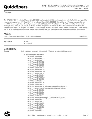
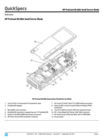
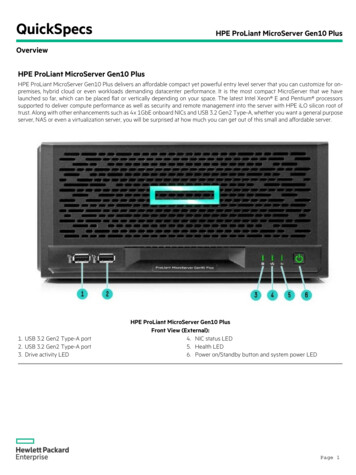
Component identificationFront panel componentsItemDescription1USB 2.0 connectors2Optical drive (optional)3Drive bays (inside)4Front bezelComponent identification 6
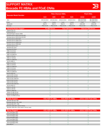
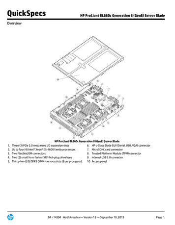
Front panel LEDs and buttonsItemDescriptionStatus1Power On/Standby buttonand system power LEDSolid green System onFlashing green (1 Hz/cycle per sec) Performing power on sequenceSolid amber System in standbyOff No power present*2NIC status LEDSolid green Link to networkFlashing green (1 Hz/cycle per sec) Network activeOff No network activity3Drive status LEDSolid green System onFlashing green Drive activityOff System in standby or no power present4Health LEDSolid blue NormalFlashing amber System degradedFlashing red (1 Hz/cycle per sec) System criticalFast-flashing red (4 Hz/cycles per sec) Power fault*** Facility power is not present, power cord is not attached, no power supplies are installed, power supply failure hasoccurred, or the power button cable is disconnected.** To identify components in a degraded or critical state, see the iLO/BIOS logs and the server troubleshooting guide.Component identification 7
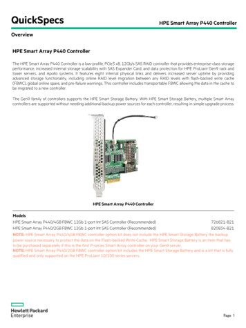
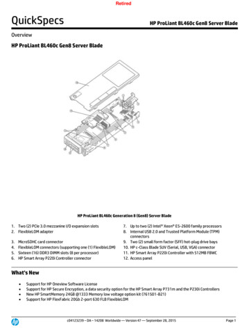
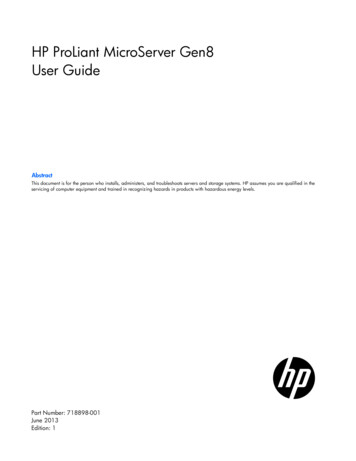
Rear panel componentsItemDescription1Kensington security slot2Power supply3Serial number/iLO information tag*4Power cord connector5Dedicated iLO 4 connector6Video connector7USB 3.0 connectors8USB 2.0 connectors9NIC connector 210NIC connector 1/shared iLO 4 connector11System fan* The serial number/iLO information tag shows the server serial number and the default iLO account information. Thesame information is printed on separate labels located on the rear panel.Component identification 8
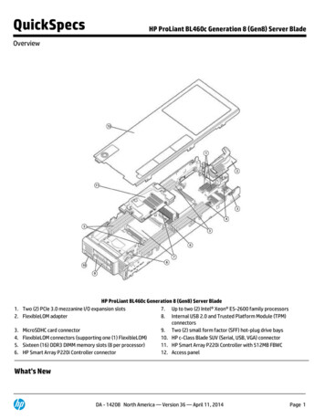
Rear panel LEDs and buttonsItemDescriptionStatus1NIC link LEDSolid green Link existsOff No link exists2NIC status LEDSolid green Link to networkFlashing green (1 Hz/cycle per sec) NetworkactiveOff No network activitySystem board componentsComponent identification 9
ItemDescription1Fan connector2DIMM slots3Front I/O connector4Processor socket5TPM connector6System battery7Mini-SAS connector8Optical drive SATA connector9Ambient temperature sensor connector1024-pin system board power connector11Internal USB 2.0 connector12microSD card slot13NMI header14PCIe2 x16 (8, 4, 1) slot15System maintenance switchComponent identification 10
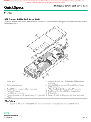
DIMM slot locationsDIMM slots are numbered sequentially (1 through 4) for the processor. The supported AMP modes use theletter assignments for population guidelines.System maintenance switchPositionDefaultFunctionS1OffOff iLO 4 security is enabled.On iLO 4 security is disabled.S2OffOff System configuration can bechanged.On System configuration is locked.S3OffReservedS4OffReservedS5OffOff Power-on password is enabled.On Power-on password is disabled.S6OffOff No functionOn ROM reads system configurationas —ReservedS11—ReservedS12—ReservedTo access redundant ROM, set S1, S5, and S6 to on.When the system maintenance switch position 6 is set to the On position, the system is prepared to erase allsystem configuration settings from both CMOS and NVRAM.Component identification 11
CAUTION: Clearing CMOS and/or NVRAM deletes configuration information. Be sure toproperly configure the server or data loss could occur.NMI functionalityAn NMI crash dump creates a crash dump log before resetting a system which is not responding.Crash dump log analysis is an essential part of diagnosing reliability problems, such as failures of operatingsystems, device drivers, and applications. Many crashes freeze a system, and the only available action foradministrators is to restart the system. Resetting the system erases any information which could supportproblem analysis, but the NMI feature preserves that information by performing a memory dump before asystem reset.To force the system to invoke the NMI handler and generate a crash dump log, do one of the following: Use the iLO Virtual NMI feature. Short the NMI header ("System board components" on page 9).For more information, see the HP SupportManual/c00797875/c00797875.pdf).Drive numberingThe server supports four LFF non-hot-plug SATA drives.Component identification 12
FBWC module LED definitionsThe FBWC module has three single-color LEDs (one amber and two green). The LEDs are duplicated on thereverse side of the cache module to facilitate status viewing.1 - Amber2 - Green3 - GreenInterpretationOffOffOffThe cache module is not powered.OffFlashing 0.5 HzFlashing 0.5 HzThe cache microcontroller is executing from within itsboot loader and receiving new flash code from the hostcontroller.OffFlashing 1 HzFlashing 1 HzThe cache module is powering up, and the capacitorpack is charging.OffOffFlashing 1 HzThe cache module is idle, and the capacitor pack ischarging.OffOffOnThe cache module is idle, and the capacitor pack ischarged.OffOnOnThe cache module is idle, the capacitor pack is charged,and the cache contains data that has not yet beenwritten to the drives.OffFlashing 1 HzOffA backup is in progress.OffOnOffThe current backup is complete with no errors.Flashing 1 HzFlashing 1 HzOffThe current backup failed, and data has been lost.Flashing 1 HzFlashing 1 HzOnA power error occurred during the previous or currentboot. Data may be corrupt.Flashing 1 HzOnOffAn overtemperature condition exists.Flashing 2 HzFlashing 2 HzOffThe capacitor pack is not attached.Flashing 2 HzFlashing 2 HzOnThe capacitor has been charging for 10 minutes, buthas not reached sufficient charge to perform a fullbackup.OnOnOffThe current backup is complete, but power fluctuationsoccurred during the backup.OnOnOnThe cache module microcontroller has failed.Component identification 13
Fan locationThe server has one system fan located at the rear of the server.T-10/T-15 Torx screwdriverThe server includes a T-10/T-15 Torx screwdriver located on the front panel. Use this screwdriver to loosenscrews during hardware configuration procedures.Component identification 14
OperationsPower up the server1.Connect the power cord to the server ("Connecting the power cord" on page 28).2.Press the Power On/Standby button.The server exits standby mode and applies full power to the system. The system power LED changesfrom amber to green.Power down the serverBefore powering down the server for any upgrade or maintenance procedures, perform a backup of criticalserver data and programs.WARNING: To reduce the risk of personal injury, electric shock, or damage to the equipment,remove the power cord to remove power from the server. The front panel Power On/Standbybutton does not completely shut off system power. Portions of the power supply and some internalcircuitry remain active until AC power is removed.IMPORTANT: When the server is in standby mode, auxiliary power is still being provided to thesystem.To power down the server, use one of the following methods: Press and release the Power On/Standby button.This method initiates a controlled shutdown of applications and the OS before the server enters standbymode.Operations15
Press and hold the Power On/Standby button for more than 4 seconds to force the server to enterstandby mode.This method forces the server to enter standby mode without properly exiting applications and the OS.If an application stops responding, you can use this method to force a shutdown. Use a virtual power button selection through iLO 4.This method initiates a controlled remote shutdown of applications and the OS before the server entersstandby mode.Before proceeding, verify the server is in standby mode by observing that the system power LED is amber.Open the front bezelIf the front bezel is not secured from inside the chassis, open the bezel.If the front bezel is secured from inside the chassis, do the following (Perform steps 1 to 3 only if the serveris turned on.):1.Power down the server (on page 15).2.Disconnect the power cord from the AC source.3.Disconnect the power cord from the server.4.Remove the chassis cover (on page 19).Operations16
5.Slide the release tab upward to unlock the front bezel from the chassis.6.Open the front bezel.Remove the front bezel1.Open the front bezel (on page 16).Operations17
2.Release the bezel hinges from the front panel.Install the front bezel1.If the chassis cover was removed, install it ("Install the chassis cover" on page 19).2.Attach the bezel to the front panel, and then close it.3.If the chassis cover was removed, do the following:a. Connect the power cord to the server ("Connecting the power cord" on page 28).b. Press the Power On/Standby button.The server exits standby mode and applies full power to the system. The system power LED changesfrom amber to green.Operations18
Remove the chassis cover1.Power down the server (on page 15).2.Disconnect the power cord from the AC source.3.Disconnect the power cord from the server.4.Disconnect all peripheral cables from the server.5.If a Kensington security cable is installed, disconnect it from the rear panel. See the security cabledocumentation for instructions.6.Loosen the rear thumbscrews that secure the chassis cover.7.Slide the chassis cover toward the rear panel, and then lift it to remove it from the chassis.Install the chassis cover1.Align the installation markers on the chassis cover with those located on the front edge of the chassis,and then slide the chassis cover back onto the server.Operations19
2.Tighten the rear thumbscrews to secure the chassis cover in place.3.Connect the peripheral devices to the server ("Connecting peripheral devices" on page 26).4.If a Kensington security cable was removed, connect it to the rear panel. See the security cabledocumentation for instructions.5.Connect the server to the network. Do one of the following:oConnect the Ethernet cable ("Connecting the Ethernet cable" on page 26).oConnect the server to the switch ("Setting up the HP PS1810-8G Switch (optional)" on page 34).6.Connect the power cord to the server ("Connecting the power cord" on page 28).7.Power up the server (on page 15).Remove the system board assembly1.Power down the server (on page 15).2.Disconnect the power cord from the AC source.3.Disconnect the power cord from the server.4.Remove the chassis cover (on page 19).5.It is recommended that you take a picture of the current system board cable connections for referenceduring server reassembly.6.If the drive cage is connected to a storage controller board, disconnect the Mini-SAS cable from theboard.7.Disconnect all cables connected to the system board.o24-pin system board power supply cableoSATA cable (only if an optical drive is installed)oMini-SAS cable (only if the drive cage is connected to the system board)oFront I/O cable (pulling up the blue loop to
HP ProLiant MicroServer Gen8 User Guide Abstract This document is for the person who installs, administers, and troubleshoots servers and storage systems. HP assumes you are qualified in the servicing of computer equipment and trained in recognizing hazards in products with hazardous energy levels. Part Number: 718898-001 June 2013 Edition: 1