Transcription
2008-01-1561Effect of Different Regenerative Braking Strategies on BrakingPerformance and Fuel Economy in a Hybrid Electric BusEmploying CRUISE Vehicle SimulationFarhad Sangtarash, Vahid Esfahanian, Hassan Nehzati, Samaneh Haddadi,Meisam Amiri Bavanpour and Babak HaghpanahUniversity of TehranCopyright 2008 SAE InternationalABSTRACTIn regenerative braking system of a HEV, the powerelectronics are controlled such that the traction motoroperates as a generator to provide negative torque onthe wheels and to produce electric energy. To developsuch an assembly of control functions it is necessary tomodel the behavior of the vehicle in a dynamicenvironment. AVL/CRUISE software is used to performvehicle simulation and brake analysis. The simulationprocedure for series braking with optimal braking feel,series braking with optimal energy recovery, and parallelbraking strategies in CRUISE software is explained.Then the braking performance and fuel economy of eachmethod is studied and compared with the others indifferent drive cycles. Finally, the advantages anddisadvantages of each method are evaluated anddiscussed.INTRODUCTIONHybrid electric vehicles have drawn a lot of attention inthe recent years because they reduce fuel consumptionand emission [1]. An important system of hybrid electricvehicles is regenerative braking system (RBS). The RBSprovides hybrid electric vehicles with capability torecover significant amount of energy during braking [23]. For this purpose, the electric motor in EVs and HEVscan be controlled to operate as a generator to convertthe kinetic and potential energy of the vehicle intoelectric energy. The recovered electric energy is storedin batteries for future use.Generally, the braking torque required to decelerate thevehicle is much larger than the torque that an electricmotor can provide. Most HEVs employ conventionalbraking system in addition to a RBS. Thus, the properdesign and control of both mechanical and electricalbraking systems are major concerns. In the area ofregenerative braking in HEVs, some studies have beenfocused on developing regenerative models [4],simulation of regenerative system models [5] and motorcontrol [6].To develop a complex assembly of control functions inregenerative braking system, it is necessary to modelthe behavior of the vehicle in a dynamic environment.AVL/CRUISE software is used to evaluate vehicleperformance and fuel economy using each brakestrategy. This beneficial software is utilized to developand optimize low emission engines, reliable power trainsand sophisticated control systems of engines, cooling,transmission, and braking systems.There is more complexity while designing a regenerativebraking system in the hybrid electric vehicles comparedwith designing conventional braking systems. The wayof distributing the required braking force betweenregenerative braking system and the mechanical frictionbraking system so as to recover the kinetic energy of thevehicle as much as possible without loosing thenecessary braking performance is the main problem,and it faces the designer with many different brakingstrategies.To develop such braking system, a hybrid series electricbus is considered in this research. The vehicle understudy is an O457 city transit bus which is hybridized to aseries hybrid electric bus in “Vehicle, Fuel, andEnvironment” Research Institute, University of Tehran.In this article, after describing the concept of three maindifferent brake control strategies of series braking withoptimal braking feel, series braking with optimal energyrecovery, and parallel braking the way of simulatingthese strategies in CRUISE software is explained. Thenthe braking performance and fuel economy of eachmethod is studied and compared with the others in adrive cycle. Finally, the advantages and disadvantagesof each method are evaluated and discussed separately.BRAKE STRATEGIESThere are two important problems in designing theregenerative braking system. First, how to distribute thetotal braking forces required between the regenerativebrake and the mechanical brake in order to recover the
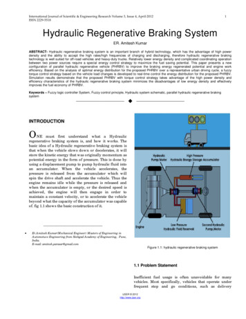
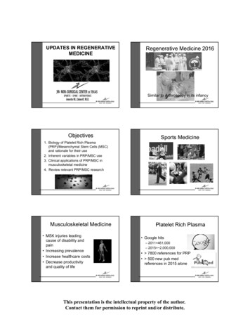
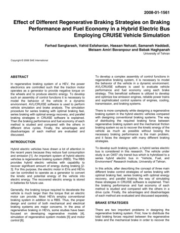
The series braking system with optimal feel consists of abraking controller that controls the braking forces on thefront and rear wheels. The purpose of this strategy is tominimize the stopping distance and optimize the driver’sfeel. The shortest braking distance and good brakingfeel require the braking forces on the front and rearwheels to follow the ideal braking force distribution,curve I [8].Figure 1 illustrates the principle of this braking controlstrategy. When the commanded deceleration is lessthan a certain value (0.2 g, for example), only theregenerative braking on the rear wheels is applied whichemulates the engine retarding function in conventionalvehicles. When the commanded deceleration is greaterthan 0.2 g, the braking forces on the front and rearwheels follow the ideal braking forces distribution curveI, shown by the thick solid line in Figure 1.In our case the braking force on the rear wheels (drivenaxle) is composed of two parts: regenerative brakingforce and mechanically frictional braking force. When thebraking force demanded for rear axle is less than themaximum braking force that the electric motor canproduce, only electrically regenerative braking will apply.But when the commanded baking force is greater thanthe available regenerative braking force, the electricmotor will operate its maximum braking torque, and theremaining braking force is provided by mechanicalbraking system.The principal of series braking system with optimalenergy recovery is to recover the braking energy asmuch as possible in the condition of meeting the totalbraking force demanded for given deceleration,according to Ehsani et al [7]. This principal is illustratedin Figure 2.j 1 gu 10.60.6j 0.9 gu 0.9j 0.8 gI curvej 0.7 gF b r-m e c hu 0.70.5j 0.6 gu 0.60.40.4j 0.5 gu 0.5j 0.4 g0.30.3u 0.4j 0.3 gu 0.30.20.2j 0.2 gu 0.2j 0.1 g0.10.1u 0.1u 0.10R e a r a x le b ra k in g f o r c e r a t ioto v e h i c le w e ig h t, F b r /M v gu 0.80.5F b r-re gF b r-re g -m a xF b r-re gkinetic energy of the vehicle as much as possible;second, how to distribute the total braking forces on thefront and rear axles so as to minimize the stoppingdistance and conserve the vehicle stability. Usually,regenerative braking is effective only for the driven axle,which is the rear axle in this study. The traction motormust be controlled to produce the proper amount ofbraking force for recovering the kinetic energy as muchas possible and, at the same time, the mechanical brakemust be controlled to meet the braking force commandfrom driver. Basically, there are three different brakecontrol strategies: series braking with optimal brakingfeel, series braking with optimal energy recovery; andparallel braking. Ehsani et al. have defined thesestrategies as follows [7].u 0.2u 0.3u 0.4u 0.5u 0.6u 0.7u 0.8u 0.9u 1000.050.10.150.20.250.30.350.40.450.5Front axle braking force ratioto vehicle weight, Fbf/MvgFbf-mechFbf-mechFigure 1: Series brake optimal feel strategyWhen the vehicle is braked with an acceleration rate ofj/g µ, the braking forces on the front and rear wheelscan be varied in a certain range. This variation range ofthe front and rear axles is shown in Figure 2 by the thicksolid line a-b, where µ 0.8 and j/g 0.7. In this case,regenerative braking should be used in priority. If theavailable regenerative braking force (maximum brakingforce produced by the electric motor) is within this range,the braking force on the rear wheels should bedeveloped only by regenerative braking withoutmechanical braking (point a). If, on the same road, theavailable regenerative braking force is less than thevalue corresponding to point b, the electric motor shouldbe controlled to produce its maximum regenerativebraking force. The front and total rear braking forcesthen should be controlled at point c (on the curve I) soas to optimize the driver feel and maintain vehicle’sstability and stearability.The parallel brake system includes both an electrical(regenerative) brake and a mechanical brake, whichproduce braking forces in parallel and simultaneously.The operating principal is illustrated in Figure 3, in whichregenerative braking is applied only to the rear wheels.The parallel brake system has a conventionalmechanical braking which has a fixed ratio of brakingforces distribution on the front and rear wheels.Regenerative braking adds additional braking force tothe rear wheels, resulting in the total braking forcedistribution curve. The mechanical braking forces on thefront and rear axles are proportional to the hydraulicpressure in the master cylinder. Because theregenerative braking force available is a function ofmotor speed and because almost no kinetic energy canbe recovered at low motor speed, the regenerativebraking force at high vehicle deceleration (e.g. j/g 0.8) isdesigned to be zero so as to maintain braking balance.When the demanded deceleration is less than thisdeceleration, regenerative braking is effective.
j 1 gu 10.60.6j 0.9 gj 0.8 gu 0.80.5au 0.70.5c0.4bj 0.5 gdI curveej 0.6 gu 0.60.4fj 0.7 gF br-reg-maxF br-regu 0.5j 0.4 g0.30.3u 0.4j 0.3 gu 0.30.20.2j 0.2 gu 0.2j 0.1 g0.10.1u 0.1u 0.4 u 0.5 u 0.6u 0.1 u 0.2 u 0.3000.050.10.15u 0.8u 0.70.20.25u 0.90.3R e ar ax le b rak in g fo rce ra tio tove h icle w e ig h t, F b r/M vgu 0.9u 10.350.40.4500.5Front axle braking force ratioto vehicle weight, Fbf/MvgFbf-mechR e a r ax le b ra k in g fo rc e ra tito v e h ic le w e ig h t, F b r/M v gFigure 2: Series brake optimal energy recovery strategyFigure 4: Hybrid drive train of O457 busj 1 gu 10.6j 0.8 gu 0.8j 0.7 g0.5u 0.7j 0.6 gI curve0.4u 0.6u 0.5Mechanical brake electrical brakej 0.4 gu 0.4j 0.3 g0.2u 0.3F br-me chj 0.2 gu 0.20.1u 0.10CD 0.55Rolling resistance coefficientCR 0.01Frontal areaAf 6.30 m2Dynamic rolling radiusRw 0.466 mOverall gearbox and differentialefficiencyEFF 0.9Curb WeightM 10230 kgGross WeightM 18000 kgj 0.1 gu 0.10Drag coefficientj 0.5 g0.3F br-regTable 1: Hybrid bus specificationsj 0.9 gMechanical brakeu 0.9u 0.20.05u 0.30.1u 0.4u 0.50.15Fbf-mechu 0.6u 0.70.20.25u 0.8u 0.90.3u 10.350.40.45Front axle braking force ratioto vehicle weight, Fbf/MvgFigure 3: Parallel brake strategyIMPLEMENTATIONDistance of gravity center fromfront axleDistance of gravity center fromrear axleHeight of gravity centerLa 4.410 mLb 1.645 mhg 0.95 mThe first step in development of brake system is tounderstand vehicle performance requirements andvehicle’s geometrical properties such as position ofcenter of mass. The vehicle which is used for currentinvestigations is hybrid version of O457 bus which hasbeen converted to a series hybrid vehicle at “Vehicle,Fuel, and Environment (VFE)” Research Institute,University of Tehran (figure 4). Specification of the busafter hybridization is given in Table 1.In HEVs the most important component which can affectthe amount of regenerated energy is the traction motor.Characteristic map of our traction motors is shown inFigure 5.Two traction motors have been used in the design ofhybrid drive train and in our modeling [1] we have onemotor instead with characteristics of one motormultiplied by two.Figure 5: Traction motor characteristics mapAs described in previous sections, the major function indesign of brake system is I curve which is result ofbraking forces at rear and front axles. Brake forces at
the front and rear axles have been determined as afunction of deceleration j:0.4Front BrakeRear BrakeRegenerative Brake0.350.3(1)0.25(2)vFbr4712 2j j173060556312 2j j8656055F/(M g)Fbf0.20.150.10.0500102030405060708090100Brake Pedal Travel (%)Figure 7: Distribution of braking force in series-optimal feelbrake strategy0.4Front BrakeRear BrakeRegenerative Brake0.350.30.25vF/(M g)These values are normalized by use of vehicle’s weight(Mvg). We have considered maximum of 0.8g forvehicle’s deceleration. It means that maximum travel ofbrake pedal is equivalent with .8g deceleration. Inaddition, the pure regenerative criterion in series brakehas been considered 0.1g.MATLAB SIMULINK has been used for implementationof described braking strategies, it consists of an stateflow controller which determines the braking modeaccording to desired equivalent deceleration andmaximum generator phase torque of traction motors andthen fraction of regenerative force, front brake force andrear brake force are calculated. At the end achievedvalues are translated to brake pressures and desiredtorque of traction motors according to the mechanicalcharacteristics of brake and drive line systems. Figure 6shows the implemented series brake-optimal feel Brakecontroller in SIMULINK.0.20.150.1Hybrid Controller0.0500102030405060708090100Brake Pedal Travel (%)Figure 8: Distribution of braking force in series-optimal energyrecovery brake strategy0.50.45Front BrakeRear BrakeRegenerative Brake0.40.35vF/(M g)0.30.250.20.15Brake ControllerFigure 6: Central controller0.10.05There are to main parts in this controller, hybridcontroller and brake controller that make the centralcontroller of hybrid drive train together. Operation ofhybrid controller is described in a separate paper whichwill be presented in the same conference. Threedifferent central controllers have been developed andfigures 7 to 9 show their output values versus percent ofbrake pedal travel which varies linearly from zero to 100for the mentioned brake strategies.00102030405060708090100Brake Pedal Travel (%)Figure 9: Distribution of braking force in parallel brake strategyAs seen in the Figure 7 and Figure 8, the value ofregenerative braking force in optimal energy recoverystrategy is more than in optimal feel strategy andconsequently there is lower amount of force on themechanical brake system. The value of regenerativebraking force for parallel brake is less than the others
and so the mechanical brake system should bear moreforce in comparison with the former strategies.To check the influence of developed brake controllers onfuel economy and braking performance, thesecontrollers have been implemented in model of hybridbus in Cruise Vehicle Simulation (Figure 10). Details ofthis modeling will be presented in the same conferencein a separate paper.motor draws from the wheels depends on the strategies.The total input energy for the optimal feel strategy is7932.9 kJ. This value for optimal energy recovery andparallel brake is 8626.2 kJ and 3710.4 kJ, respectively. Itmeans that 50%, 54% and 23% of the output energy thatleaves the electric motor can be recaptured for thesebraking strategies, respectively. As it can be seen thisvalue for all the strategies is really considerable and thebest result is for optimal energy recovery.Figure 11: The velocity profile of NuremburgR36 drive cycleFigure 10: Model of hybrid bus in CruiseImplemented controllers are converted to Dynamic LinkLibrary file by use of Real-Time Workshop which is atool of MATLB. Finally, the central controller has beenintegrated into the model by use of MATLAB Interfacemodule of Cruise software. This model contains avehicle module which stands for road loads and brakingforces oriented from rolling resistance, drag force andgrad force and brake modules which are capable ofmodeling different brake systems.RESULTSTo simulate the bus in Cruise a drive cycle should beemployed to investigate the performance of each ofbraking systems and compare the performance andenergy recovery of different regenerative brakingsystems. The employed drive cycle is Nuremberg R36city bus drive cycle. It is a European standard drive cycleand has lots of start and stop conditions, so it candistinct the ability of each brake strategy. The velocityprofiles of Nuremburg drive cycle is illustrated in Figure11.Figures 12 to 14 present the total mechanical energythat is transferred to wheels from electric motor versustime when the vehicle passes the drive cycle and alsothe mechanical energy that is transferred to electricmotor from wheels when it brakes for RBS with optimalfeel, optimal energy recovery, and parallel brake,respectively.The output mechanical energy follows the drive cycleand it is the same for all the strategies and is equal to15966.8 kJ. But the input mechanical energy that electricIn fact, the input mechanical energy that enters theelectric motors is not equal to real value that saves inbatteries because of electric motor, inverter and batterycharging efficiencies. Considering these values leads toreal amount of energy saving that is presented in figures15 to 17 for the mentioned braking strategies,correspondingly. The overall output electric energy frombatteries is the same for all the strategies and equals to19580.5 kJ. To ensure that the amount of batteriesoutput and input energies are equivalent to the electricalenergy received by electric motors, simulations whereperformed in pure electric operation of vehicle to avoidthe probable conflict with produced energy from dieselgenerator. The overall saved energy for the optimal feelstrategy is 6092.6 kJ. This value for optimal energyrecovery and parallel brake is 6669.5 and 2607.2,respectively. It means that 31%, 34% and 14% of theoutput electric energy can be recaptured for thesebraking strategies, respectively. As it can be seen thisvalue for all the strategies is still considerable.
Figure 12: Electric motor input and output mechanical energyfor optimal feel strategyFigure 13: Electric motor input and output mechanical energyfor optimal energy recovery strategyFigure 14: Electric motor input and output mechanicalenergy for parallel brake strategyFigure 15: Overall input and output electric energy for optimalfeel strategyFigures 18 and 19 present the total mechanical energyentered the electric motor and total energy saved inbatteries for the mentioned braking strategies for bettercomparison. All of the presented results are for emptybus. In order to study the effect of weight, the amount ofsaved energy in batteries for the braking strategies arepresented for full load vehicle in Figure 20. As it isshown in this figure the trends are the same. The overalloutput energy for this case is 34209.5 and the totalsaved energy in batteries for the optimal feel, optimalenergy recovery and parallel brake strategies is10191.3, 12483.8, and 5029.9, respectively. It meansthat for full vehicle the amount of recaptured energy isequal to 30%, 36% and 15% of overall output electricenergy for these braking strategies, correspondingly.The results for full vehicle are similar to empty vehicle tosome how. The difference between two first strategies ismore noticeable for this case, because for full vehiclethe braking torque demand from electric motor is moreand the optimal energy recovery can recapture moreenergy.Figure 16: Overall input and output electric energy for foroptimal energy recovery strategy
Figure 17: Overall input and output electric energy for forparallel brake strategyFigure 18: Input energy of Electric motor for the mentionedbraking strategiesFigure 20: Overall electric out put energy and saved energy into the batteries for the mentioned braking strategy in fullvehicle caseThe fuel consumption for these strategies in Nurembergdrive cycles are 30.3 litre/100km, 29.55 litre/100km and36.17 litre/100km for optimal feeling, optimal energyrecovery and parallel brake strategy in empty bus case,correspondingly. This value for conventional bus is45.01 litre/100km and for hybrid bus with a simplethermostat control strategy without RBS is 39.5litre/100km resulting into 12.2% improvement. Details ofthe conventional bus simulation are described in anotherpaper presented at the same conference. It means thatthe fuel consumption improves 32.7%, 34.3% and 19.6%for these strategies, respectively. It shows that in such astart-stop drive cycle how much the braking strategy isimportant in improvement of fuel economy with about20% due to the RBS. The results for both optimal feeland optimal energy recovery are similar to some extend.It happens because the braking deceleration in most ofthe drive cycles is usually less than 0.1g and it leads tohave the same performance for the both brakingstrategy. If the drive cycle has higher brakingdeceleration the difference between these two strategiescan become significant.In order to evaluate the performance of these brakingstrategies a deceleration test with same pedal force(50%) is performed. In this case, the vehicle brakes fromits maximum speed, 85 km/h, and the amount of savedenergy, the time, distance and deceleration curve andsome other outputs are evaluated.Figure 19: Overall saved energy in to the batteries for thementioned braking strategyFigures 21 to 23 present distance, velocity anddeceleration curves for each strategy. With the samepedal force the parallel brake makes the vehicle stopsooner because both mechanical and regenerativebraking systems operate simultaneously. The results forelectric motor torque, speed and mechanical input powerduring braking are shown in figures 24 to 26 for thedifferent braking strategies. It can be seen that for theoptimal energy braking the input power and the relatedtorque of electric motor is more than the others leadingto more energy saving. In Figure 27 the amount ofenergy saved in the batteries for the mentioned brakingstrategies are compared during braking from 85 km/h tostop condition. In this case the overall kinetic energy of
bus, mv2/2, is equal to 2851 kJ. Figure 27 shows that inseries optimal feel, series optimal energy recovery andparallel brake strategies 1018 kJ, 1090 kJ and 527 kJ ofthis energy can be saved, respectively. These valuesare equal to 35%, 38%, and 18% of the total kineticenergy of the vehicle. In fact, the deceleration of such abraking is high and in all strategies the mechanicalbraking is operating. If instead of deceleration about 0.4g we have a value around 0.2 g, the percentage ofsaved energy will increase significantly because themechanical braking system can not dissipate such alarge value of kinetic energy.Finally, for better understanding the value of SoC rise forthis test in different control strategies are comparedtogether. If the initial SoC at the start of braking processis equal to 55%, after vehicle stop this value willincrease to 55.94%, 56.01% and 55.49% for thementioned braking strategies, respectively. Theseresults are illustrated in Figure 28.Figure 23: Distance, velocity and acceleration curves forparalel brake strategyFigure 24 Electric motor Torque, Speed and mechanical powercurves for optimal feel brake strategyFigure 21: Distance, velocity and acceleration curves foroptimal feel brake strategyFigure 25: Electric motor Torque, Speed and mechanical powercurves for optimal energy recovery brake strategyFigure 22: Distance, velocity and acceleration curves foroptimal energy recovery brake strategy
Table 2: Summery of improvement made on fuel economy inNuremburgR36 drive ional45.01-Hybrid without RBS39.512.2%Series braking with optimalbraking feel30.332.7%Series braking with optimalenergy recovery29.5534.3%Parallel36.1719.6%Figure 26: Electric motor Torque, Speed and mechanical powercurves for parallel brake strategyCONCLUSIONFigure 27: Total energy saved in batteries for all brakingstrategies in braking from maximum speed to zeroAt first, an explanation about the hybridizationadvantage and some descriptions about the usedstructure for the hybrid bus are presented. Then thedifferent braking strategies for regenerative brakingsystem in hybrid vehicles are described. By simulatingthe bus with these braking strategies in AVL/Cruise theenergy saving and the related fuel saving are evaluatedfor each strategies. It is observed that in a drive cyclelike Nuremberg using these strategies leads torecapturing 30%, 36% and 15% of overall output electricenergy, correspondingly. These amounts of energysaving in addition to other advantage of hybridizationprovide an improvement of 32.7%, 34.3% and 19.6% infuel economy for these strategies related to conventionalbus, respectively. It shows that in such a start-stop drivecycle how much the braking strategy is important inorder to fuel economy improvementThe braking performance of the bus for all strategies isevaluated and it is concluded that it is considerably finefor all RBS strategies. During braking not only the safetyof bus and braking performance are improved becauseof employing an extra braking system but also aconsiderable part of the kinetic energy recaptured in thebatteries for future use instead of dissipation inmechanical braking system.In addition, the capability of the Cruise software packagein designing hybrid vehicles and analyzing the employedbraking strategy is shown. The Cruise software providesvaluable assistance to vehicle designers and significantunderstanding to researchers in the field of hybridvehicles.Figure 28: Batteries SoC rise for all braking strategies inbraking from maximum speed to zeroIt can be understood from the results of SoC changesduring the constant deceleration braking test that in lowvelocities (large time), the change in SoC is very smalldue to low efficiency of electric motor. This is becausethe regenerated energy is very small even with thesufficient braking torque. Summery of improvementmade on fuel economy is shown in Table 2.Finally, it can be concluded that the employed brakingstrategy has strong effect on both fuel economy andperformance of the hybridized vehicle.
ACKNOWLEDGMENTSThis work was supported by the Vehicle, Fuel andEnvironment (VFE) research institute of University ofTehran in cooperation of Isfahan University ofTechnology and Iran-Khodro Company as parts of theHybrid Vehicle Propulsion System Program, supportedby Vehicle Design office of the ministry of industries andmines. The authors would like to thank AVL for use ofCruise software.REFERENCES1. Khanipour A, Esfahanian M, Sangtarash F, Amiri M,“An Investigation on The Effect Of ration,” Proceedings of ESDA2006, 8thBiennial ASME Conference on Engineering SystemsDesign and Analysis, July 4-7, 2006, Torino, Italy.2. Wicks F,Donnelly K, “Modeling RegenerativeBraking and Storage for Vehicles,” S. Hall, IEEEEnergy Conversion Eng. Conf., 1997, 2030-2035.3. Gao Y, Chen L, and Ehsani M, “Investigation of theeffectiveness of regenerative braking for EV andHEV,” Society of Automotive Engineers (SAE) J.,SP-1466, Paper No. 1999-01-2901- 1999.4. Cikanek S. R., Bailey K. E., “Regenerative BrakingSystem for Hybrid Electric Vehicle,” in Proc. Amer.Control Conf., Anchorage, AK, May 2002, 31293134.5. Yeo H, Kim H, “Hardware in the Loop Simulation ofregenerative Braking for a Hybrid Electric Vehicle,”in Proc. Inst. Mech. Eng. Vol. 216, 2002, pp. 855864.6. Gao H, Gao Y, Ehsani M, “Design issues of theswitched reluctance motor drive for propulsion andregerative braking in EV and HEV,” IEEE ElectricMach. Drives. Conf., (2001), 571-575.7. . Ehsani M., Gao Y., Gay S., Emadi A., Modernelectric hybrid, and fuel cell vehicles, CRC press,2005, Washington, D.C., USA, pp. 338-343.8. Gao Y, Ehsani M, “Electronic braking system of EVand HEV integration of regenerative braking,automatic braking force control and ABS,” FutureTransportation Technology Conference, CostaMesa, CA, August 2001.
AVL/CRUISE software is used to evaluate vehicle performance and fuel economy using each brake strategy. This beneficial software is utilized to develop and optimize low emission engines, reliable power trains and sophisticated control systems of engines, cooling, transmission, and braking systems.