Transcription
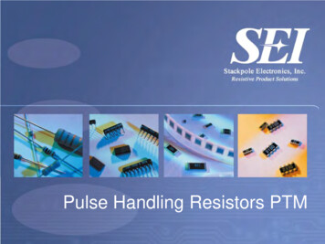
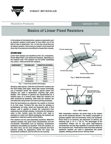
VISHAY BEYSCHLAGResistive ProductsApplication NoteBasics of Linear Fixed ResistorsIn the shadow of microelectronics, passive components suchas discrete resistors would seem to have fallen out of thefield of view in electronics. Yet, it is the rare circuit that cando without resistors. And a look at a modern circuit board willshow that it has become more difficult to locate them visually.Protective lacquerThin film resistive layerPure tin contactOVERVIEWLinear fixed resistors are classified as film, foil, composition,Power Metal Strip , and wirewound resistors, depending onthe material used. Film resistors can be further subdividedinto carbon, metal and thick film resistors.COMPONENTTECHNOLOGYRESISTIVE MATERIALMeander trimmingCarbonFilmMetalThin film inner contactPasteResistorsPower Metal Strip num oxide ceramicFig. 2 - Metal film chip resistorFig. 1 - Linear fixed resistors technologiesGoing by sales figures, metal film and thick film resistors arethe most widely used types. Aside high volume commodityuse of standard carbon film resistors special carbon filmresistors are used in applications requiring high pulsestability. Film resistors in general are characterized by aresistive layer on a ceramic base. Metal film resistors areoften produced by sputtering, while thick film resistors aremanufactured using screen and stencil printing processes.Film resistors can be used essentially anywhere. Metal filmresistors possess very good noise characteristics and lownon-linearity. Parameters such as tolerance, temperaturecoefficient, and stability are excellent. Thick film resistors, onthe other hand, can be more cheaply produced and havesufficient quality for applications where low noise, lowtemperature coefficient, and low drift are not a priority.Document Number: 28771Revision: 11-Nov-08Protective lacquerAlumina ceramic rodSteel termination capplated pure tin on nickelFig. 3 - MELF resistorWith composition resistors, the entire body of the resistoracts as the resistance element. The resistor composition ispressed together with the termination wires and hardened.Since there is no trimming, the tolerances on delivery arerelatively high ( 10 %, 20 %). The advantages of thecomposition resistor are its very good high-frequencycharacteristics and the high capability to overload relative tothe component size. These factors mean that these relativelyexpensive resistors are used in applications like powersupplies, welding controls and as “dummy loads”.For technical questions, contact: m1APPLICATION NOTEOnce the terminations are attached, the resistor is trimmedto its final value. Formerly this was done by grinding orsandblasting, but today, lasers are frequently used. A finallacquer coat is applied to protect the component frommechanical and climatic stresses. Commonly the resistancevalue is then marked using the familiar color rings orstamped on in plain text. Before packaging, the resistors aresubjected to extensive quality control testing.Metal film resistive layer
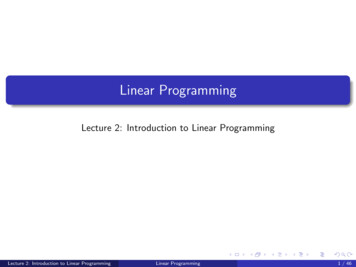
Application NoteVishay BeyschlagBasics of Linear Fixed ResistorsTinnedtermination wiresPermanentterminationsCopper terminal withsolderable finishResistancecolor codingSolid carbonresistance elementResistive ationTerminal-to-element weldFig. 4 - Composition resistorFig. 6 - Power Metal Strip resistorThe interior of a wirewound resistor consists of a ceramic orfiberglass base wound with resistor wire to the desiredresistance value. The wire ends are pressed or brazed to thecaps. The outstanding characteristic of this type of resistor isthe very high surface temperature it can take, up to 450 C,which makes it very tough indeed. Their areas of applicationare comparable to those of the composition resistor, with thereservation that the high frequency characteristics of thewirewound resistor are substantially worse.The metal foil resistor consists of an electrically insulatedetched metallic foil mounted on a material of high heatconductivity. Metal foil resistors are used today in largequantities as low-ohm current measuring resistors (shunts),as well as precision resistors for measurement applications.The most important requirements for these applications arelow temperature coefficient, low thermoelectrical potentialdifference with reference to copper, and high long-termstability.DuroplastcoveringAdhesive andinsulationAluminumbaseMetal foilCopperterminationcontactsAPPLICATION NOTEFig. 5 - Wirewound resistorPower Metal Strip resistor construction consists of solid, selfsupporting, resistance element which is welded to copperterminals. The resistive element is trimmed to a desiredresistance value by increasing the current path. Finally theresistor body is encapsulated and the terminals plated forsolderable connection. Power Metal Strip resistors arecharacterized by very low resistance values (1 Ω to 100 µΩ),tight resistance tolerance ( 1 % standard, 0.5 %available), low temperature coefficient (TCR) (below 75ppm/K) and low thermal EMF (below µV/K). Power MetalStrip resistors are commonly used as shunt resistors. Areasof application include DC/DC converters, Li-Ion batterymanagement, power supplies, and automotive controls forbody, power train and safety.ProtectivelacquerSnPb hot-diptin coatingCu/Ni/Sncontact zoneFig. 7 - Metal foil resistorThese requirements are met extremely well by foil resistorsmanufactured by etching technology and usingmanganese-ceranin alloys. Among their other technicaladvantages are extremely low inductivity and good pulseloading capability. Foil technology is particularly suitable forresistors in the 2 mΩ to 150 kΩ range.Besides the basic types which have been discussed so far,there are several special resistor types: Trimmable resistors which are trimmed by laser to thenominal value only after installation in the application; crowave Fusible resistors which become high-resistive when adefined current is exceeded; Customer specific resistor arrays configuration.www.vishay.com2For technical questions, contact: filmresistors.thinfilmchip@vishay.comDocument Number: 28771Revision: 11-Nov-08
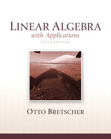
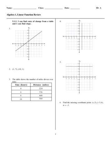
Application NoteVishay BeyschlagBasics of Linear Fixed ResistorsThe essential characteristic of a linear resistor is a constantquotient of voltage and current, or put differently:UR ---- constantIThe ideal resistor never deviates from its rated value, isunaffected by temperature, can handle any electrical load,and does not change its specifications over the course of itslife.However, in the real world physics always gets in the way ofthis ideal. Thus, even with something that at first glanceseems as simple as a resistor, there are properties that adevelopment engineer should consider, whether foranalogue or digital circuits. If he wants to guarantee a certaincircuit behavior, such as very high pulse stability or a goodsignal to noise ratio, there is no way to get around perusal ofthe specification sheets. In the following all relevantcharacteristics will be discussed one by one.Nominal Value: The nominal value is the value the resistorshould have at 20 C based on its design. Although it istheoretically possible to produce any kind of resistor, inpractice the need for inventory simplification has led theindustry to settle on the E-series in accordance withIEC 60063. Based on the principle of constant tolerance andresistor values of 1 Ω, 10 Ω, 100 Ω and 1 kΩ, it forms ageometric sequence of ratings by the following formula:k (n10 )m(n: number of values within a decade; n 6, 12, 24, 48, 96,192; m: element counter; m 0,., n-1; number rounded to2 or 3 significant digits)Tolerance: The tolerance on delivery is the range withinwhich the resistor can deviate percentually from the value atthe time of delivery. During operation further deviation canoccur, such as drift and temperature coefficient. Often thevalues from the E-series are combined with the tolerance sothat the spreads of two successive ratings overlap slightly.Example:E24/5 %E96/1 %E192/0.5 %Temperature Coefficient of Resistance (TCR):Unfortunately, the resistance value changes in a slightlynon-linear fashion with temperature. The temperaturecoefficient α is the relative change in the resistance valuewithin a given temperature interval.R ϑ - R 20α --------------------------------------R 20 ( ϑ - 20 C )ϑ:Rϑ:R20:Operating temperature in CResistance value at temperature JResistance value at 20 CThe TCR is thus the mean rise in the temperature resistancecurve and is valid only in the temperature range specified.Usually, recommended temperature ranges (climaticcategories) are used in standards, e.g. - 55 C ϑ 125 Cfor TCR 50 ppm/K (1). Using ΔR Rϑ - R20 andΔϑ ϑ - 20 C, the maximum resistance change can becalculated for any temperature change within this range:ΔR--------- Δ ϑ αR 20ΔR Resistance changeΔϑ Temperature rise (K)Converting the deviation into percentage scales the TCRspans a permissible range within the resistance value varies.Resistance ChangeCHARACTERISTICS1.0 %0.5 % 50 ppm/KPermitted Range0.0 %- 50 ppm/K- 0.5 %- 1.0 %- 75- 50- 250255075100125150175Temperature ( C)Fig. 8 - Example of possible relative changes in theresistance value due to the TCRNote(1) ppm/K parts per million per Kelvin, 1 ppm 1 · 10-6Document Number: 28771Revision: 11-Nov-08For technical questions, contact: m3APPLICATION NOTEStability: The resistance value can change under thermal,electrical, or mechanical influence. Stability classes indicatethe maximum permissible change. Stability is tested byprocedures defined in standards. Short-term tests includeoverloading, mechanical sturdiness of the terminations,resistance to soldering heat, rapid temperature changes, andvibrations. Long-term testing includes criteria such asclimate sequences, damp heat, long-term exposure to themaximum permissible temperature and long-term exposureat 70 C ambient temperature with cyclic electrical load(load life).
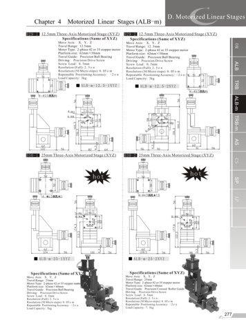
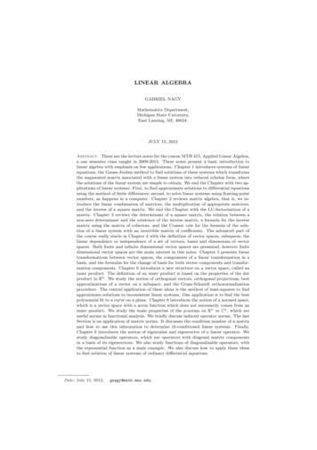
Application NoteVishay BeyschlagBasics of Linear Fixed ResistorsThis table shows the permissible resistance value change tothe assignment of stability classes:STABILITYCLASSESSHORT-TERMTESTINGLONG-TERM TESTING2 (2 % · R 0.1 Ω) (0.5 % · R 0.05 Ω)1 (1 % · R 0.05 Ω) (0.25 % · R 0.05 Ω)0.50 (0.50 % · R 0.05 Ω) (0.10 % · R 0.01 Ω)0.25 (0.25 % · R 0.05 Ω) (0.05 % · R 0.01 Ω)0.10 (0.10 % · R 0.02 Ω) (0.05 % · R 0.01 Ω)0.05 (0.05 % · R 0.01 Ω) (0.025 % · R 0.01 Ω)Rated dissipation: The rated dissipation is the maximumdissipation the resistor is capable of up to a defined ambienttemperature (the rated temperature, typically 70 ºC). At thisloading, the temperatures at the component do not exceedthe maximum. Above this temperature the resistor can onlyutilize a reduced level of power. This is described by aderating curve:Pulse Stability: If a resistor is exposed to pulses instead ofconstant loading, it can accept multiples of its rated loadingfor short periods without impairing its long-term stability.In order to get comparable measurements, there are twostandardised pulses according IEC 60115-1, 4.27: 1.2/50 µsand 10/700 µs. The first figure stands for the rise time and thesecond for the pulse duration (pulse voltage drop to 50 %).The 1.2/50 measurement is taken with 5 pulses at intervalsof at least 12 s; the 10/700 measurement with 10 pulses atintervals of at least 60 s. The pulse load capabilities for theseconditions are established based on suitable criteria, i.e. anappropriate permissible resistance change after pulse load.We prefer to set such criteria in relation the product’s longterm stability, e.g. 0.5 %.For a resistor to possess sufficient pulse suitability for aspecific application, the following criteria must be met: The average load must not be greater than the ratedloading at the required ambient temperature; The permissible pulse loading as a function of the pulseduration must not be exceeded;100 % The pulse voltage at the resistor must be lower than thepermissible pulse peak voltage.PP700%- 55 C 70 C 125 CAmbient TemperatureFig. 9 - A typical derating curveOperating Voltage: This is the highest DC voltage or theeffective sinusoidal AC voltage that can be continuouslyapplied to the resistor.APPLICATION NOTENon-Linearity: Due to inhomogeneities in the resistormaterial or substrate and/or poor transitions betweenterminations and resistor material, even linear resistors arenot completely linear, i.e. the current-voltage characteristic isnot exactly linear. The non-linearity is determined bymeasuring the 3rd harmonic of a 10 kHz sine oscillation. Thevoltage ratioU 10 kHzA 3 20 lg -----------------U 30 kHzis a quality criterion of a resistor. Faulty resistors can beidentified by excessively low A3 values. The measurementprocedure is specified by IEC/TR 60440.Noise: There are two kinds of noise: the thermal noise andthe current noise by the applied voltage. While thermal noiseremains constant over a wide frequency range (white noise),current noise declines with rising frequency. IEC 60195 laysdown the measurement arrangement and procedure, inorder to ensure that noise voltage specifications arecomparable. This standard also includes a code number forthe noise of an individual resistor, the current noise index.www.vishay.com4Thermal Resistance: The thermal resistance counteractsthe dissipation of the heat generated in the resistor. Sincethermal resistance depends in large measure on theassembly conditions, the value given in catalogs is takenfrom a standardised test assembly.For a specific application, the following formula is used todetermine the temperature increase over the ambienttemperature:Δ ϑ P R thP Power load of the resistor (W)Rth Actual thermal resistance (K/W)High Frequency Characteristics: In addition to theresistance value, as frequency increases parasitic propertiesbecome noticeable. This includes the inductivity of thewindings in cylindrical resistors and the capacity betweencomponent terminations. A resistor has good high frequencycharacteristics when the parasitic elements in the frequencyrange in question are negligible.A resistor should also be modelable, i.e., capable ofdescription using a simple equivalent circuit diagram. Its highfrequency characteristics must be reproducible in seriesproduction.Special trimming processes for film resistors and windingprocesses for wire-wound resistors substantially improve thehigh frequency characteristics of these components.For technical questions, contact: filmresistors.thinfilmchip@vishay.comDocument Number: 28771Revision: 11-Nov-08
Application NoteVishay BeyschlagBasics of Linear Fixed ResistorsCHARACTERISTICS IN FIGURESThe following table brings together some typical figures. It ignores specialities, such as ultra-precision metal film resistors( 0.01 % tolerance, TCR 2 ppm/K) or metal film resistors for temperature above 155 C.POWERMETAL STRIPRESISTORSCARBON FILMMETAL FILMTHICK FILMMETAL FOILCARBONCOMPOSITIONResistanceValue10 Ω to 22 MΩ0.22 Ω to 22 MΩ1 Ω to 100 MΩ2 mΩ to 1 MΩ1 Ω to 20 MΩTolerance[%] 2 to 10 0.1 to 2 1 to 5 0.005 to 5 5 to 20 0.1 to 10 0.5 to 1TemperatureCoefficient[ppm/K]- 200 to - 1500 5 to 50 50 to 200 2 to 50- 200 to - 1500 1 to 200 30 to 250MaximumOperatingTemperature[ C] 155 155 155 150 150 400 275RatedDissipationP70 [W]0.25 to 20.063 to 10.063 to 0.250.25 to 100.25 to 10.25 to 1000.1 to 5Stability atP70 (1000 h)ΔR/R [%] 0.8 to 3 0.15 to 0.5 1 to 3 0.05 4/- 6(typical - 3) 1 to 10 1 to 2OperatingVoltageUmax. [V]200 to 100050 to 50050 to 200200 to 500150 to 35025 to 1000P 70 x RCurrentNoise [µV/V] 1 0.1 10 0.0252 to 6negligiblenegligibleNon-linearityA3 [dB] 100 110 50negligible 60negligiblenegligibleWIREWOUND0.1 Ω to 300 kΩ 0.1 mΩ to 1.0 ΩSHAPES AND SIZESThe most elementary distinction is between leaded and SMD (2). High-power resistors are also available with termination clamps.Surface-mounted resistors are further subdivided into cylindrical MELF (3) and rectangular chip devices.The following table decodes the size designations. It applies to film resistors in general. Wirewound, composition and foil resistormanufacturers often use proprietary sizes.SHAPESTANDARDIZED PEREXAMPLE0204EN (5)RC 3715 MEIAJ (6)3216ENRR 3216 MCylindrical (MELF)Rectangular (Chip)Inch Size1206Dimensions: Maximum in 1/10 mmSequence: Length - DiameterResistor, CylindricalL 3.7 mm; Dia. 1.5 mmAPPLICATION NOTEDIN (4)DESCRIPTIONDimensions: Rounded. Maximum in mmSequence: Diameter - LengthDia. 2 mm; L 4 mmDimensions: in 1/10 mmSequence: Length - WidthL 3.2 mm; W 1.6 mmDimensions: in 1/100"Sequence: Length - WidthResistor, RectangularL 0.12"; W 0.06"Notes(2) SMD - Surface Mounted Device(3) MELF - Metal Electrode Face bonding, component fastened to the circuit board by its metal surface (termination surface)(4) DIN - German Standards Institute (Deutsches Institut für Normung)(5) EN - European Norm(6) EIAJ - Electronic Industries Association of JapanDocument Number: 28771Revision: 11-Nov-08For technical questions, contact: m5
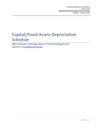
Application NoteVishay BeyschlagBasics of Linear Fixed Resistors041402070204Standard per DINStandard perMELFMINI-MELFMICRO-MELFDIN020702040102ENRC 6123MRC 3715MRC 2211MStandard 50525IEC, ENRR 3216MRR 2012MRR 1608MRR 1005MRR 0525MFigure 10. Common shapes and sizesTRENDSSTANDARDISATIONDevelopments in the world of resistors are by no means over.Miniaturization will continue in the years to come. Size 0402and even 0201 will increasingly be used for applications whereevery square millimeter counts, such as cellular phones.Individual resistors will be combined in arrays with theobjective of gaining space and functional performance.The properties of resistors are described in the datasheet ofthe manufacturers, which come in a variety of scopes andcomprehensiveness or even terminology. Almost needless tomention that also the tests and applied requirements rarelymatch.Another trend runs opposite to this. There is an increasingdemand for SMD resistors that can handle dissipation powerover 0.25 W and are stable under mains voltage. The demandfor MELF size 0207 underlines this development.APPLICATION NOTEEspecially for voltage divider and feedback circuits Thin FilmChip Resistor Arrays became the preferred solution. Suchchip arrays combine two and more resistors on one ceramicsubstrate and have special advantages in terms of stability,tolerance matching and TCR tracking.Along with the extension of resistance value ranges upwardsand downwards, high frequency properties and pulse stabilityare being improved.Specialities are increasingly coming into their own. Forexample, trimmable (by the component user) resistorseliminate the need for costly, time-consuming trimming byexpensive mechanical trimmer potentiometers.Increasing applications in sensors, automobiles, industry andmobile telephones will further anchor the role of the resistor asthe most-needed electronic component.Fortunately some technical cultures have supported theharmonisation of such descriptions, definitions, methods andrequirements into widely accepted standards. This road waspaved by the principles of involvement of all interested partiesand of consensus between all those. It had started within thenational environments (e.g. DIN, JIS, EIA) long time ago andmatured from there to international levels (e.g. CECC,CENELEC and finally IEC). Nowadays the nationalcommittees act as members of the IEC (7) in the drafting andmaintenance of component standards, which are thenadopted back on the national level. In the EuropeanCommunity, CENELEC (8) acts as an intermediate ratificationlevel before these standards are published by nationalstandardisation bodies (e.g. DIN, BSI, UTE, . ).Component standards usually come in a hierarchical structureof generic, sectional and detail. While a generic specificationdeals with the terms, definitions and preselection of applicabletest methods e.g. for all fixed resistors, a sectionalspecifications provides more specific details for a general kindof products, e.g. for surface mount resistors. Lowest level andthus closest to the individual product or product family is thedetail specification with its exact details and requirements,including sophisticated test schedules.Notes(7) IEC - International Electrotechnical Commission; www.iec.ch(8) CENELEC - Comité Européen de Normalisation Electrotechnique (European Committee for Electrotechnical Standardization); www.cenelec.euwww.vishay.com6For technical questions, contact: filmresistors.thinfilmchip@vishay.comDocument Number: 28771Revision: 11-Nov-08
Application NoteVishay BeyschlagBasics of Linear Fixed ResistorsINTERNATIONAL RESISTOR STANDARDSHIERARCHICAL LEVELSTANDARDOWNERIEC 60115-1IECEN 60115-1CENELECGenericIEC 60115-2 (9)IECEN 140100 (10)CENELECEN 140101-806CENELECIEC 60115-8 (9)IECEN 140400 (11)CENELECEN 140401-801CENELECEN 140401-802CENELECEN es(9) Outdated documents, currently under revision(10) To be succeeded by EN 60115-2(11) To be succeeded by EN 60115-8Component users benefit from this standardisation firstthrough the unambiguous perception of all details in aproduct description and then may even be able to save theefforts involved in establishing an own company-internal setof component specifications.QUALITY ASSESSMENT The superior level is marked with the TechnologyApproval, which in addition to the requirements ofQualification Approval assesses the effectiveness of thewhole established quality management system towardssafeguarding the production only of compliantcomponents.Any granted approval is expressed by a certificate, of whichthe manufacturer will be pleased to provide a copy. Anapproval can be verified any time in the certificates databaseon the IECQ (13) website. Attestation of the component'sconformity does not require any individual certificates, butmay simply be expressed by a proper standard referenceand application of the CECC logo as the mark of conformityon the package label. Under Qualification Approval the quality of finishedcomponents is assessed through lot-by-lot and periodicinspections in comparison to the requirements prescribedby the detail specification, regardless of how theestablished quality management system would contributeto achieving the compliance.Fig. 11 - CECC LogoNotes(12) CECC CENELEC Electronic Components Committee(13) IECQ IEC Quality Assessment System for Electronic Components; www.iecq.orgDocument Number: 28771Revision: 11-Nov-08For technical questions, contact: m7APPLICATION NOTENow component standards or specifications not only supportthe harmonisation of the product descriptions, but also serveas a major prerequisite for a reliable quality assessment. Ofcourse every vendor feels entitled to assess the quality of hisproducts on his own, but how would these individualself-assessments compare? Already the CECC (12) haddeveloped a “Harmonized System of Quality Assessment forElectronic Components” which involves accredited NationalSupervision Inspectorates responsible for auditing andcertification. In 2003 IECQ had taken over the qualityassessment of CECC. This system offers different kinds ofapproval: Under Capability Approval the general capability of anorganisation to produce a wide variety of different productswithin a range of technology in line with prescribedrequirements is assessed through dedicated qualificationsamples, much like under Qualification Approval.
Application NoteVishay BeyschlagBasics of Linear Fixed ResistorsOnce an approval has been granted, the benefit is with thecomponent users again, who can save efforts for extensiveincoming inspections and vendor audits and instead rely onan independent inspectorate supervising the production andverifying compliance with the stated requirements on a tightperiodical schedule.BIBLIOGRAPHYZinke, O.; Seither, H.: Widerstände Kondensatoren, Spulenund ihre Werkstoffe, Springer-Verlag BerlinHoffmeister, Georg: Widerstandskunde für Elektroniker - DieFestwiderstande in Berechnung und Anwendung, RPBTaschenbücher 1/6, Franzis Verlag GmbH, München 1978MINI-MELF and MICRO-MELF, Application Guide, TheBEYSCHLAG Company 1993APPLICATION NOTEMetal Film Resistors - Precision, The BEYSCHLAGCompany 1993www.vishay.com8For technical questions, contact: filmresistors.thinfilmchip@vishay.comDocument Number: 28771Revision: 11-Nov-08
Basics of Linear Fixed Resistors Application Note Vishay Beyschlag Document Number: 28771 For technical questions, contact: filmresistors.thinfilmchip@vishay.com www.vishay.com Revision: 11-Nov-08 3 APPLICATION NOTE CHARACTERISTICS The essential characteristic of a linear resistor is a constant quotient of voltage and current, or put differently: