Transcription
Siemens Sm@rt DASUser Guideusa.siemens.com/smartgear
Sm@rt DASbetween the general informationcontained in this publication andthecontents of drawings orsupplementarymaterial or both, thelatter shalltake precedence.Qualified PersonSafety Precautions(a) Only qualified persons familiar withthe construction and operation of thisequipment should perform workdescribedin this set of instructions. Suchwork should be performed only afterreading this complete set ofinstructions.(b) Follow safety related work practices,as described in NFPA 70E, at all times.(c) Hazardous voltages in electricalequipment can cause severe personalinjury or death. Energizing thisequipment for the first time after initialinstallation or maintenance ispotentially dangerous. Inspection andmaintenance should be performed onthis equipment and equipment to whichpower has been cut off, disconnected,and electrically isolated so that noaccidental contact can be made withenergized parts.(d) Some types of electrical equipmentwill cause harmonics in the electricalsystem which may result in overheating.Consider this condition whendetermining this equipment loading, aspossible de-rating of equipment may benecessary.ImportantThe information contained herein isgeneral in nature and not intendedforspecific application purposes. It doesnot relieve the user of responsibility touse sound practices in application,installation, operation, andmaintenance of the equipmentpurchased. Siemens reserves the rightto make changes in the specificationsshown herein or to make improvementsat any time without notice orobligations. Should a conflict ariseFor the purpose of this manualandproduct labels, a qualified person isone who is familiar with the installation,construction, operation or maintenanceof the equipment and the hazardsinvolved. In addition, this person hasthe following qualifications:(a) is trained and authorized tode-energize, clear, ground, and tagcircuits and equipment in accordancewith established safety practices.(b) is trained in the correct care and useof protective equipment such as rubbergloves, hard hat, safety glasses or faceshields, flash clothing, etc., inaccordance with established safetypractices.(c) is trained in rendering first aid.Signal WordsThe signal words "Danger," "Warning"and "Caution" used in this manualindicate the degree of hazard that maybe encountered by the user. Thesewords are defined as:Danger - Indicates an imminentlyhazardous situation which if notavoided, will result in death or seriousinjury.Warning - Indicates a potentiallyhazardous situation which, if notavoided, could result in death or seriousinjury.Caution - Indicates a potentiallyhazardous situation which, ifnotavoided, may result in minor ormoderate injury.Dangerous ProceduresIn addition to other proceduresdescribed in this manual as dangerous,user personnel must adhere to thefollowing warnings:(a) Danger! High Voltage. Qualifiedpersonnel only. Lock off all power tothis equipment before working inside.Always work on de-energizedequipment. Always de-energizeequipment before performing any tests,maintenance or repair.(b) Warning! Always performmaintenance on the interrupting deviceafter the closing mechanism(s) aredischarged.(c) Caution! Always let an interlockdevice or safety mechanism perform itsfunction without forcing or defeatingthe device.(d) Caution! Hydrocarbon spraypropellants and hydrocarboncompounds will cause degradation ofcertain plastics. Contact your localSiemens representative before usingthese products to clean or lubricatecomponents during installation ormaintenance.
Sm@rt DASTable of ContentsChapter 1Chapter 2Chapter 3Chapter 4Chapter 5Introduction4Overview4Sm@rt DAS System5Introduction5Controller5Gateway6Breaker Comm Modules6Breaker Requirements7System Interface8Introduction8One Switch and Light per Breaker8One Switch for System, One Light per Breaker8MODBUS ring the Sm@rt DAS System11MODBUS Function Codes11Siemens Sm@rt DAS Communication Module12-20Commissioning/Common Troubleshooting21Introduction21Basic Commissioning21-24These instructions do not purport to include all details or variations in equipment, nor to provide for every possiblecontingency that may occur in connection with installation, operation or maintenance. Should further information be desiredor should particular problems which are not covered sufficiently for the purchaser’s purposes, the matter should referred to thelocal Siemens sales offi ce. The contents of this instruction manual shall not become part of or modify any prior or existingagreement, commitment or relationship. The sales contract contains the entire obligation of Siemens. The warranty containedin the contract between the parties is the sole warranty of Siemens. Any statements contained herein do not create newwarranties or modify the existing warranty.
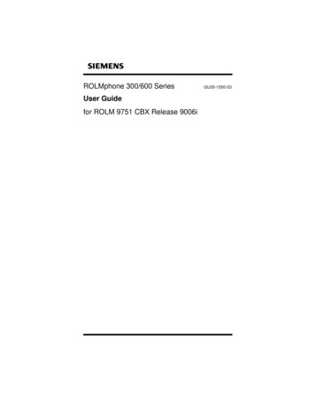
Chapter 1IntroductionOverviewSm@rt Dynamic Arc-Flash Sentry (DAS): Sm@rt DAS is asolution that allows users the ability to automatically togglebetween nominal trip settings and a predefined set of lowertrip settings (also known as a maintenance mode) used whenfacility personnel are nearby the electrical equipment orwithin the arc flash boundary. Sm@rt DAS can be activatedby a simple contact, such as a switch so a wide range ofactivation devices can be used to enable DAS.The purpose of this manual is to help users develop safe andefficient procedures for operation and maintenance of theSm@rt DAS system. The Sm@rt DAS system is used to controlmaintenance mode of VL and WL breakers in Type WLSwitchgear, SB Switchboards, P4 and P5 Panelboards. Thecontroller switches DAS on/off for a combination of up to 9VL/WL breakers. For larger systems, multiple controllers willbe used. The Sm@rt DAS controller allows the panel torespond to triggering of maintenance mode via digital inputs,MODBUS or HMI commands. The system can be activated overan HMI without a switch. Additionally, each input has anoutput confirming activation of maintenance mode.Activation switch(1 per breaker)Indicator light(1 per breaker)ControllerHMI (optional)GatewayModbus networkLow-VoltagePower BreakerInsulated CaseBreakerFigure 1.1: Sm@rt DAS Architecture4Molded CaseCircuit BreakerMolded CaseCircuit BreakerMolded CaseCircuit Breaker
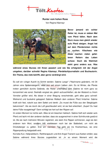
Chapter 2Sm@rt DAS SystemIntroductionDigital Input - Turn on DAS for all BreakersThe Sm@rt DAS system consists of a controller, VL and WLbreakers with MODBUS communication modules, and aMODBUS RTU to TCP/IP gateway.When this input is activated, DAS on all breakers will beturned on.Digital Input - Local OverrideControllerWhen this input is activated, Sm@rt DAS can’t be utilized toturn on breaker DAS remotely using Sm@rtGear Mobilesolftware. DAS can only be activated locally using the Sm@rtDAS activation switch.The heart of the Sm@rt DAS system is the controller. Itconsists of a PLC with pre-loaded software which is the samefor every Sm@rt DAS system. All configuration is done at thefactory. The program is flexible and configuration settings areaccessible over MODBUS.Digital Outputs (9)Each breaker in the Sm@rt DAS system has an assignedoutput from the controller. When it is confirmed that abreaker is in maintenance mode, "24V DC" appears in theoutput. The outputs can drive indicators (typically blue LEDs)for visual confirmation of system status.Figure 2.1 highlights the inputs and outputs available on thecontroller.Digital Inputs (9)Each breaker that has Sm@rt DAS is assigned a digital input. Itmoves from left to right and top to bottom in the lineup. Theinput requires 24V to activate. This is typically done via anactivation switch.Ethernet connectionThe Sm@rt DAS controller communicates with the breakersvia Ethernet connected to an Ethernet-MODBUS RTU gateway.An Ethernet switch or router can be inserted between thetwo to expand communication possibilities.Sm@rt DAS Controller9 Digital Inputs (24VDC)PowerSupply(120VACor 4O.5O.6O.7O.8O.9Ethernetconnection toMODBUSgateway/routerEthernetModbusTCP/IP9 Digital Outputs (24VDC)Figure 2.1: Sm@rt DAS Controller5
Chapter 2Sm@rt DAS SystemGatewayThe Gateway converts MODBUS RTU that is the native communication protocol for the VL breaker to MODBUS TCP/IP.The WL breaker with COM35 communication module alreadycommunicates MODBUS TCP/IP and doesn’t require the Gateway for communication protocol conversion. It is factory configured and no additional user set up is required.Ethernet GatewayPowerSupply(120VACor igure 2.2: Ethernet GatewayBreaker Comm ModulesFigure 2.3: VL MODBUS moduleFigure 2.4: WL MODBUS moduleCOM21 (VL Breakers – Switchboards and Panelboards)COM35 (WL Breakers – Switchgear and Switchboards)The COM21 module connects VL breakers to the Sm@rt DASsystem.The COM35 module connects WL breakers to the Sm@rt DASsystem.6
Chapter 2Sm@rt DAS SystemBreaker RequirementsThe Sm@rt DAS system requires certain features in both theWL and VL breakers. This section highlights the requirementsfor breakers as well as the features for each breaker withSm@rt DAS.Figure 2.5: WL BreakersFigure 2.6: VL BreakersWLVLFeatures ETU 776 required COM35Features ETU 586 COM21Normal settings Parameter A on breaker Default settings are minimum Adjust on breaker to changeNormal settings Parameters on breaker Default settings are minimum Adjust on breaker to changeDAS (maintenance mode) settings Parameter B on breaker Default settings are minimum Adjust on breaker to changeDAS (maintenance mode) settings Stored in controller Default settings are minimum- 1.25X on short time- 100 ms on short time delay- 1.25X on IOC7
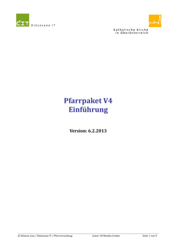
Chapter 3System InterfacesIntroductionOne Switch and Light per BreakerThere are three different ways to activate the Sm@rt DASsystem:This is the default configuration. The first 9 inputs have adedicated output that indicates when breaker has enteredmaintenance mode. Each input activates maintenance modefor one breaker. There is also a dedicated output for eachbreaker that confirms when the breaker has enteredmaintenance mode. Figure 3.1 highlights the configuration.For example, Input 0 (I.0) and Output 0 (O.0) will be the inputand output controlling maintenance mode on breaker one. Activation Switch HMI MODBUS communicationThis section will deal with the different schemes andimplementations available and how they function.One Switch for all BreakersThe 10th input has a connection for a single switch to turnDAS on for all breakers. Each breaker has a dedicated light.24VDCSwitchInputsPowerSupply(120VACor re 3.1: Sm@rt DAS Controller with one switch and one light per breaker8
Chapter 3System InterfacesMODBUS CommunciationThe controller can be accessed over MODBUS TCP/IP toremotely activate maintenance mode. If maintenance modeis activated over MODBUS, it works the same as if the switchwas turned on.The default IP address of the controller is 192.168.0.74 butcan be specified at the time of ordering. For the controller,the next address would be 192.168.0.76 followed by192.168.0.78. The increase of 2 on the address is due to thegateway filling in between these values.In order to activate DAS over MODBUS, you will need aMODBUS program. Siemens has a program called Sm@rt DASMODBUS Communication Module that can be used to readand write settings for Windows 7 and later.For full MODBUS functionality see Section 4, CommunicationsFigure 3.5: Controller withMODBUS Communication9
Chapter 4CommunicationsIntroductionThe Sm@rt DAS controller uses MODBUS TCP/IP as itscommunication protocol. A computer or SCADA system canconnect to the controller via Ethernet either directly into thecontroller (Figure 4.1) for a brief period to change settings orthrough a router for more permanent connections.The DAS controller acts as a slave when interfacing with aBuilding Management System or other supervisory system.Table 4.2 shows the MODBUS system codes if integration isneeded to upstream devices.In order to permanently connect the Sm@rt DAS to anupstream system, the second RJ45 port of the gateway can beused. An Ethernet switch will need to be placed between thecontroller and gateway (Figure 4.2, 4.3) if several externalconnections are needed.Figure 4.1: Ethernet portTo upstreamSCADA systemEthernetGatewayNetworkSwitchSm@rt DASControllerFigure 4.2: Example of network switch10Figure 4.3: Interface with network switch if included
Chapter 4CommunicationsConfiguring the Sm@rt DAS SystemCodeDescriptionThere are two methods of changing settings on the Sm@rtDAS controller:01Read coil status02Read input statusTo configure with HMI – refer to Chapter 303Read holding registersTo configure with MODBUS communication04Read input registersMODBUS function codes05Force single coilTable 4.1 shows MODBUS function codes used to access datafrom devices. For Sm@rt DAS, Code 03 is used to read holdingregisters and Code 16 is used to write the holding registers.06Preset single register10Write multiple registers15Force multiple registers16Preset multiple registersTable 4.1: Common MODBUS function codes11
Chapter 4CommunicationsSiemens Sm@rt DAS Communication ModuleA secondary option for access to Sm@rt DAS system is usingthe Sm@rt DAS Controller Configurator available through theSiemens Download Center. It can be used by connectingdirectly to the PLC or connecting through an Ethernet switch.It is used to change maintenance mode settings and canremotely activate maintenance mode. The software iscompatible with Windows 7 and later.Figure 4.4: Main Screen - Sm@rt DAS Controller Configurator12
Chapter 4CommunicationsSet up and installation of Sm@rt DAS ControllerConfigurator ModuleThe setup file can be downloaded from the SiemensDownload Center. Once downloaded to the user’s computer,open the file.Connecting to Sm@rt DAS System:Network switch: This should be the easiest connection. Justplug an Ethernet cable into the network switch and youshould be connected to the network. Additionally, you canconnect through the gateway directly.Direct to the PLC: Start by plugging an Ethernet cable directlyinto the PLC and ensure all other network connections areclosed. Once plugged in, open the control panel on the PCand follow the following menu options: Go to the Network and Sharing Center Select “Change Adaptor Settings” Right-click on “Local Area Network” and select “Properties” Select Internet Protocol Version 4 (TCP/IPv4) and click“Properties” Use the following IP address: - Type in 192.168.1.xx(typically something like 0-35 should work) - Type255.255.255.0 for subnet mask - Click “OK”You should now be able to connect to the PLC.Note: When directly connected to the PLC, you will not beable to turn DAS on until the Ethernet connection of the PLCis plugged back in.13
Chapter 4CommunicationsConfigure IP address of Sm@rt DAS ControllerClick on change target PLC and enter the IP address of thecontroller default is 192.168.1.235Once the controller is connected the top left corner of thescreen will show a green check mark for communicating asshown in Figure 4.5Figure 4.5: Home Screen with Green ConnectionFigure 4.6: PLC IP Address14
Chapter 4CommunicationsChange IP address of Sm@rt DAS ControllerClick on change PLC Network settings PLC and enter the newIP address as shown in figure 4.8. This is typically done ifthere multiple controllers in a lineup to prevent issuesconnecting.Once the new IP address is entered click the save icon andthen you may need to re-enter the PLC address to reconnectonce the IP address changes.Figure 4.7: Home Screen Location of Change PLC Network SettingsFigure 4.8: PLC IP Address Change15
Chapter 4CommunicationsSet IP address of BreakersClick on set all breaker IP to enter the master IP address forthe breakers if they are all on same network. For most Sm@rtDAS systems they will be under one MODBUS TCP/IP toMODBUS RTU converter and share the same IP address.Once set this will make it easier to access the slave addresses.Figure 4.9: Home Screen Location of Set IP address of BreakersFigure 4.10: IP Address of Breakers16
Chapter 4CommunicationsWiring WizardThe wiring wizard is used to match breaker numbers withinput and output switches on the Sm@rt DAS controller. Thisallows user to adjust which controller outputs and inputs mapto which lights.For the most part this will be done in factory, but if a breakeris added with DAS in the field this allows it to be assigned.Figure 4.11: Location of Wiring WizardFigure 4.12: Example of Wiring Wizard Inputs17
Chapter 4CommunicationsEdit BreakerThe edit breaker screen allows the user to enter the IP andslave address of each breaker they wish to control.Once the IP address is defined the user must select whetherthe circuit breaker they are using is a WL, VL, or 3VA basedupon the drop down selection.Figure 4.13: Location of Edit BreakerFigure 4.14: Example of Edit Breaker Inputs18
Chapter 4CommunicationsTesting the systemOnce the user inputs all of the settings into the system, theDAS system can be tested by selecting DAS breaker modebutton from the home screen.The screen on figure 4.16 should show up the user can thenclick on turn off DAS or turn on DAS button highlighted totoggle the settings. Once the settings change the blue lightshould also come on with the respective breaker andmaintenance mode settings can be confirmed on the circuitbreakerFigure 4.15: Location of Set DAS Breaker ModesFigure 4.16: Breaker DAS Module19
Chapter 4CommunicationsAccess to Sm@rt DAS trip unitsTrip unit data accessConnecting to the breakersThe IP address for the first ten trip units is 192.168.0.75. Ifmultiple controllers are on requested on same network attime of order next IP address for 10 breakers would be192.168.0.77 ( .02). The slave address to each device isdocumented on the drawings submitted with the switchboardor switchgear. The addresses start at one and increment byone top to bottom left to right.Using Sm@rt DAS also allows for direct access to the breakerif the user wishes to make changes to trip unit settings, getstatus etc. It is possible to gain network access two ways :For permanent access, a network switch should be purchasedwith the Sm@rt DAS system at time of buy. Then gainingaccess is as easy as plugging into the networkFor temporary access it is possible to connect directly to thegate way over EthernetRefer to the Circuit Breakers with Communication CapabilitySENTRON WL and SENTRON VL MODBUS System Manual forregister informationNote: if you have more than 9 devices and want externalnetwork access note that at order time20
Chapter 5Commissioning/TroubleshootingIntroductionThis section discusses the steps that should be taken duringcommissioning to verify the Sm@rt DAS system’sfunctionality. This section will also go into some basictroubleshootingBasic commissioning:Review the schematics provided with the gear. This willidentify the location of the switches and lights as well aswhich breakers have DAS.Once the main incoming power to the system is available, theSm@rt DAS system should come up. Ensure Sm@rt DAS controller has control power bychecking the LEDs in Figure 5.2. The Sm@rt DAScontroller will be in the main device aux compartment ifavailable or in the panel mounted aux compartment. For WL breakers: set all parameter A, B settings into thetrip unit For VL breakers: Use nominal settings in the breaker. Themaintenance mode instantaneous settings need to be setat or below the nominal instantaneous settings. Ensureyou change maintenance settings in Sm@rt DAScontroller if needed. When setting up the VL breaker,ensure “instantaneous” is turned on in the circuit breaker.Ensure all of the Comm modules have power by checkingfor green LED indicators on the communication modules.The COM35 modules for the WL are located in the WLbreaker compartment, centered above the WL breaker.The COM21 is located in panel-mounted compartmentswith the VL breakers or in a full aux compartment if theyare individually mounted. See Figure 5.1 for an exampleof which LED lights should be lit on comm.Power LEDsInput LEDsOutput LEDsFigure 5.1: LED to inspect on comm. modulesFigure 5.2: LED to inspect on controller21
Chapter 5Commissioning/TroubleshootingCommissioning - WL Sm@rt DAS Review drawings to identify location of Sm@rt DASswitches or HMI. The elevation will show the location ofthe switches/HMI highlighted in Figure 5.3. The electrical view will show the breakers with Sm@rtDAS highlighted in Figure 5.4. Parameter A should be shown on the center of the tripunit screen as in Figure 5.5. Turn the DAS switch; theblue light should come on next to the switch. The WLbreaker trip unit should also now show Parameter B onthe screen.Figure 5.3: Location of switches and lightsFigure 5.5: Indication of active WL parameter set.Figure 5.4: Location of circuit breakers with DAS22
Chapter 5Commissioning/TroubleshootingCommissioning - VL Sm@rt DAS Review drawings to identify the location of Sm@rt DASswitches or HMI. The elevation will show the location ofthe switches/HMI highlighted in Figure 5.6. The electrical view will show the breakers with Sm@rtDAS highlighted in Figure 5.7. Starting with the VL breakers, go to the trip unit, scrolland select “View parameter screen”. Then select “Viewprotection” and then scroll through and reviewinstantaneous pickup. It should be set to either thedefault settings, which are the minimum, or the settingsinput by the user. Turn the DAS switch “on” for the VL breaker. The bluelight should then come on. Then refresh theinstantaneous pickup setting by scrolling up or down onthe keypad. Scroll back to review the instantaneoussettings. They should be 1.25x the breaker rating or thesettings set earlier into the controller. The preset valuesfor short time delay are 100ms and short time pickup is1.25x the breaker rating.Figure 5.6: Location of switches and lights If the VL maintenance modes are changed, always testmaintenance mode and verify the new maintenancemode settings on the VL.Figure 5.7: Location of circuit breakers with DAS23
Chapter 5TroubleshootingDAS is not turning onVerify Switch to Controller Wiring Locate the Sm@rt DAS controller in the gear. When theswitch is closed, one of the green LED highlighted in redwill turn on indicating the 24V signal gets to the PLC. Ifthe light does not come on, check wiring from PLC toswitch and from switch to 24V power supply. Ensurewires were connected between any shipping splits.Verify Controller to Indicator Light Wiring The corresponding green LED highlighted in blue on thecontroller indicates the breaker is in maintenance mode.If this light is green and the blue light does not come on,check output wires from the controller to the light andfrom the light to the power supply. Ensure wires wereconnected between any shipping splits.Verify Communication Modules have power Check each communication module and verify each hasgreen LEDs on indicating power as per commissioningrequirements. If not, verify power connection wiring.Power LEDsVerify device is communicating Each device will have a MODBUS communication light –verify that it is green as well when the switch is closed.Check wiring to ensure all connections are made,especially across shipping splits.Verify VL settings Ensure VL breaker nominal settings are at or higher thanmaintenance mode instantaneous settings, and thatinstantaneous settings are turned on.Additional support Review the FAQ document for additional support topics.It is available through the Siemens Download Center. Support, service, parts and repairs are available sevendays a week, 24 hours a day, 365 days a year. CallSiemens Industry Customer Care Center (ICCC) at800-333-7421.Input LEDsOutput LEDs24
Notes25
Notes26
Notes27
Published bySiemens 2020Siemens Industry, Inc.5400 Triangle ParkwayNorcross, GA 30092Siemens Technical Support: 1-800-333-7421info.us@siemens.comOrder No. PDOM-SDUGU-0120Printed in USA-CPAll Rights Reserved 2020, Siemens Industry, Inc.usa.siemens.com/smartgearThe technical data presented in this document is based on an actual caseor on as-designed parameters, and therefore should not be relied upon forany specific application and does not constitute a performance guaranteefor any projects. Actual results are dependent on variable conditions.Accordingly, Siemens does not make representations, warranties, orassurances as to the accuracy, currency or completeness of the contentcontained herein. If requested, we will provide specific technical data orspecifications with respect to any customer’s particular applications. Ourcompany is constantly involved in engineering and development. For thatreason, we reserve the right to modify, at any time, the technology andproduct specifications contained herein.
Sm@rt DAS system. The Sm@rt DAS system is used to control maintenance mode of VL and WL breakers in Type WL Switchgear, SB Switchboards, P4 and P5 Panelboards. The controller switches DAS on/off for a combination of up to 9 VL/WL breakers. For larger systems, multiple controllers will be used. The Sm@rt DAS controller allows the panel to