Transcription
GESecurityVigilant Fire & Life SafetySmall Analog SystemsOverviewFeaturesThe GE Vigilant VS1 intelligent life safety system offers the speedof high-end intelligent processing in a configuration that delivers an uncomplicated solution for small to mid-sized applications.With intelligent detection, electronic addressing, automatic devicemapping, optional Ethernet connectivity, and a full line of easilyconfigured option cards and modules, this quick-to-install systemoffers versatile features that benefit building owners and contractors alike. Comes standard with one loop that supports up to 64 intelligentdevices of any type and two Class B NACs.The VS1 provides one Class B analog device loop that supports upto 64 device addresses, and two Class B Notification Applianc eCircuits (NACs). Optional Class A device wiring is available with theuse of a module. Form C contacts for alarm and trouble, Form A for supervisory Electronic addressing with automatic device mapping Optional Ethernet port for diagnostics, programming Supports systemwide strobe synchronization Two programmable switches with LEDs and custom labeling On board NACs support Genesis horn silence over two wires andUL 1971-compliant strobe synchronization Optional Class A wiringThis life safety system features an attractive contemporary designthat fits with any decor. Its gently curved doorfront offers a distinctive flair with available red or silver finishes. Controls are discreetlyinset behind a striking black bezel. Supports up to eight serial annunciators, (LCD, LED-only, andgraphic interface).The VS1 supports a wide range of accessories and related equipment, including: Upload/download remotely or locally Intelligent modules, detectors, and bases Can use existing wiring for most retrofit applications Supports V-Series single and multisensor detectors Two-level maintenance alert reporting R-Series remote annunciators Pre-alarm and alarm verification by point Option cards that expand system capacity and extend systemcapabilities. Adjustable detector sensitivity 4 x 20 character backlit LCD displayVS1 IntelligentLife Safety SystemData Sheet M85005-0131 Issue 1Not to be used for installation purposes. Page 1 of 8
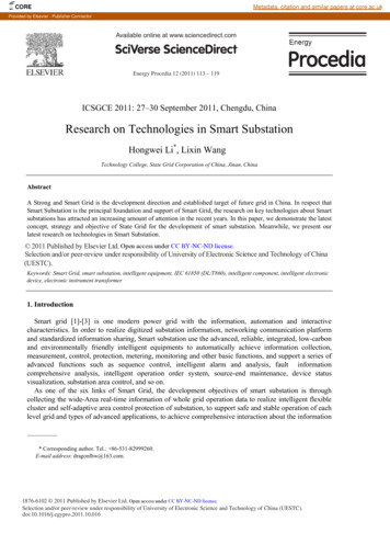
ApplicationProgrammingThe VS1 life safety system is an easy-to-use intelligent solution forsmall to mid-sized buildings. Advanced analog technology deliversthe benefits of quick and uncomplicated system installation, while aclean and easy-to-operatate user interface makes panel operationand system maintenance quick and intuitive.VS1 life safety systems are simple to set up, quick to program, andeasy to maintain. The auto programming feature quickly gets thepanel operational using factory default settings. Basic zone andpoint settings can be programmed easily through the front panelinterface, so the system is up and running in no time.The smart choiceElectronic addressing eliminates the tedium of setting dipswitches,and automatic device mapping ensures that each device resides onthe system at its correct location. Meanwhile, innovative programming features allow the system designer to customize powerfulbuilt-in features to precisely suit the needs of the building owner.Versatility built right inTwo fully-programmable front panel switch/LED combinations provide an added measure of simplicity. Their slide-in labels take themystery out of custom applications, and present a clean finishedappearance.Perfect for retrofitsThe VS1 is particularly well-suited to retrofit applications. Allconnections are made over standard wiring – no shielded cablerequired. This means that in most situations existing wiring can beused to upgrade a legacy control panel to V-Series technology without the expense or disruption of rewiring the entire building.Signals with a differenceVS1 NACs are configurable to fully support the advanced signalingfeatures of GE Genesis and Enhanced Integrity notification appliances. These devices offer precision synchronization of strobesto UL 1971 standards. For Genesis devices, enabling this featureallows connected horns to be silenced while strobes on the sametwo-wire circuit continue to flash until the panel is reset.Clear-cut remote annunciationRemote annunciation is a strong suit of the VS1. Up to eight annunciators can be installed on a single system. Compatible annunciators include a range of LED and LCD models that provide zone orpoint annunciation, as well as common control capabilities.For more advanced system configuration and correlation groupsprogramming, the VS1 interfaces to a PC running compatible VS-CUsoftware. This option offers full system configuration in the familiarWindows operating environment. Connection is typically madeto a laptop through the panel’s optional modem or Ethernet port,which can also be used to connect a system printer.Among the many advanced features of the VS1 is its optional network card. This module provides a standard 10/100 Base T Ethernet network connection that permits access to the control panelfrom any remote location with the correct communications protocols. The connection can be used to download to the panel from theVS-CU, or upload and view system reports using the VS-CU.Available system reports include: Correlation groups Device maintenance Internal status System status Dialer Device detailsHistorySystem configurationWalk testOperationThe front panel provides an easy-to-use operator’s interface, aswell as all the necessary controls for front panel programming.A large back-lit 80-character LCD displays system status, eventdetails, and programming prompts. Large tactile control buttons areeasy to see in low light conditions, and bright multi-color LEDs offerat-a-glance status nerConfigurableThe VS1 also supports graphic annunciation with optional RAGraphic Annunicator interface modules. Each interface providescommon control, indicators, and 32 LEDS. Consult the OrderingInformation section for details.A complete line of accessoriesThe VS1 life safety system is supported by a complete line ofintelligent detectors, modules and related equipment. Consult theOrdering Information section for details.SystemLEDsControlbuttonsData Sheet M85005-0131 Issue 1Not to be used for installation purposes. Page of 8
Control buttonsButtonResetACK/PanelSilenceSignal SilenceDrillRemoteDisconnectLeft arrowRight arrowUp arrowDown mablebuttonsSystem LEDsDescriptionInitiates a system reset.Silences the panel and remote annunciators duringan active trouble, supervisory, or alarm event andacknowledges new event activations.Alarm mode: Silences active notification appliances.Pressing Signal Silence a second time turns NACs back on.Initiates a drill confirmation. Pressing drill a second timeturns off the drill function.Dialer: Disables or enables dialer.Dialer set to modem only: Disables or enables CentralStation communciation.Display mode: Moves the cursor to the left.Menu mode: Toggles between programming selections.Display mode: Moves the cursor to the right.Menu mode: Retrieves a programming option’s sub menuand toggles between a programming option’s selections.Display mode: Advances to the previous event.Menu mode: Moves the cursor up.Display mode: Advances to the next event.Menu mode: Moves the cursor down.Display mode: Displays selected event details.Menu mode: Retrieves a programming option’s submenu or jumps to the Save function in the menu.Entry mode: Enters the selected data into the system.Display mode: Exits the detailed information display.Menu mode: Exits the current menu level.Entry mode: Clears the current entry.Display mode: Enters the menu modeMenu mode: Exits menu modeEnters a space, such as a space between words.Entry mode: Pressing a button once enters the numberon the button. Pressing the button twice enters thesecondary value.These buttons can be programmed to control or operatea device, zone, or Panel NAC. The buttons can be labeledwith a slip-in insert.LEDDescriptionFire AlarmTroubleRed LED. On steady when there is an active alarm.Yellow LED. Flashes when there is a fault on amonitored circuit or system component, or when acircuit is disabled.SupvYellow LED. On steady when there is an activesupervisory event.AC PowerGreen LED. On when the panel has AC power.DisableYellow LED. Double-flashes when there is a disabled circuit, alarm relay, or remote annunciator.Ground Fault Yellow LED. On steady during an active ground fault.TestYellow LED. Flashes when performing an audiblewalk test. Steady indicates a silent test.MonitorYellow LED. On steady when there is an activemonitor event.ServiceYellow LED. Indicates that detector needs servicing.DetectorSignalYellow LED. On steady indicates that NAC circuitsSilenceare turned off but the panel is still in alarm.RemoteYellow LED. On steady indicates that the dialerDisconnectis disabled or that the alarm relay is enabled ordisabled when the dialer is set to modem only.DrillYellow LED. Indicates that the panel is in drill.ResetYellow LED. Indicates that the panel is resetting.PanelYellow LED. Indicates that the panel has beenSilencesilenced during an active trouble, supervisory, oralarm event and indicates that new event activations have been acknowledged.User keysYellow LED. Programmable.Panel Operation OptionsLanguageMarketplaceAC fail delayZone resoundReset inhibit afterNACs turn onEnglish or FrenchU.S. or CanadaOff: Off-premise notification of an AC power failure isimmediate.1 to 15 hours: Delays the off-premise notification ofan AC power failure by the time period selected.On: NACs resound each time a device in the zonegoes into alarm even if they were silencedOff: Inhibits the NACs from turning on again (afterthey were silenced) when a second device in the zonegoes into alarm.Off: Panel reset is operational immediately.1 minute: Panel reset is inhibited for one minute.Auto signalsilenceDay startNight startDateMappingLCD bannerEvent notificationOff: Allows immediate silencing of signals from anoff-normal condition using the Signal Silence button5 to 30 minutes: Delays the silencing of signals froman off-normal condition by disabling the SignalSilence button for the time period selected.Start time for daytime sensitivityStart time for nighttime sensitivityU.S.: MM/DD/YYYYCanada: DD/MM/YYYYDisabled: Device mapping is not availableEnabled: Device mapping is availableBanner text for line one and line two. Each line iscapable of up to 20 characters.Zone: When a device is a member of a zone, only thezone information is sent to the LCD display, LEDs,printer, and dialer.Zone/device: Zone information is sent to the LCDdisplay and LEDs. Device information is sent to theprinter and dialer.Device: Only device information is reported.Data Sheet M85005-0131 Issue 1Not to be used for installation purposes. Page of 8
Wiring & ConfigurationNotification appliance circuits (TB2)Alarm, trouble, and supervisory relay (TB3)The VS1 comes equipped with two notification appliance circuits.Each circuit can be individually configured for continuous, temporal,synchronized, and coded output.The trouble relay is normally-open, held closed, and opens on anytrouble event or when the panel is de-energized. The supervisoryrelay is normally-open, and closes on any supervisory event. Thealarm relay changes over on any alarm event.Circuit SpecificationsCircuit Type 2 Class B, Class A optional when Class A card is installed.Each circuit is 2.5 amps.Voltage24 VFWRCurrent3.75A total (115/230 60hz)3.0A total (230v 50hz)2.5 A max per circuitImpedance26 Ω total, 0.35 µF maxEOLR15 K Ω, ½ WClass B wiringNAC1 - -NAC1 NAC2 NAC2 TB2 -EOLRMarking indicates output signal polarity when the circuit is active.Class B reverseswiring when the circuit is not active. Wire notificationPolarityappliancesaccordingly. Notification appliance polarity shown inNAC1 active state.NAC1 NAC2 -DeviceloopNAC2 - ---EOLRTB2 system provides one device loop circuit that can be used withTheNAC3any mixof-detectors and modules. The loop circuit is supervised forNAC3 opens, shorts, and grounds.NAC4 -Auxiliary & Smoke power outputs (TB3)The control panel provides two auxiliary power outputs which canbe used for powering ancillary equipment such as remote annunciators and two wire smoke detectors. Aux 2 can be softwareselected to operate continuous. The circuit is supervised for shortsand grounds.Note: For a complete list of devices that can be connected tothis circuit, refer to the VS1 and VS2 series compatibility list (p/n3101065).Circuit specificationsCircuit voltage rangeResettable circuit(Aux power 2)Continuous circuit(Aux power 1) -Annunciator loop (TB4)The control panel provides a connection for up to eight seriallydriven and supervised remote annunciators.Channel 1 Channel 2––Circuit specificationsTB4Device loopsClass B (Style Y) or Class A* (Style Z)AnnunciatorCircuit voltage2.55 VCH1 ( ) INCircuit current30 mA maxCH1 (–) INCircuit impedance Up to 8 annunciators or 4000 feet, 18AWG wire-Data Line -LoopdeviceChannel 1 Channel 2Channel 1 Channel 2 orCH1 ( ) INCH1 ( ) INCH1 (–) INCH1 (–) INCH2 ( ) INCH2 ( ) INCH2 (–) INCH2 (–) INChannel 1 Channel 2 --Data LineLoopdeviceLoopdevice– - Loop cardCH2 (–) IN - CH2 ( ) INClass AClass A wiringLoop 1 PRI24 VDC nominal at 500 mA. Use this circuit forpowering two-wire smoke detectors.Class BLoop cardLoop 1 SEC21.9 to 28.3 V24 VDC nominal at 500 mANote: Any current above 0.5 amp connected to both Aux 1 and 2 will reduce the totalavailable NAC power by that amount. TB6Relay circuits can only be connected to power-limited sources. Loop 1 SECLoop 1 PRISupervisoryForm A24 VDC at 1 A resistive TB2TroubleForm C24 VDC at 1 A resistive -NAC2 Class B wiringAlarmTypeVoltageEOLR Circuit Specifications NAC4 Device loops1 Loop- Class B or- Class A supporting up to 64 deviceTB6addresses.CommunicationMaximum 20 V peek-to-peeklinevoltageClass A wiringCircuit current0.5 A maxNAC1 total, 0.5 µF, maxCircuit impedance 66ΩNAC1 Isolators64 -maximum NAC2 -Relay specifications–TB4AnnunciatorCH1 ( ) INCH1 (–) INCH2 ( ) INCH2 (–) INData Sheet M85005-0131 Issue 1Not to be used for installation purposes. Page of 8
Option CardsV-Series panels are supported by a complete line of modules andrelated equipment that enhance performance and extend systemcapabilities. Option cards are easy to install and set up. They simplyplug directly into the control panel main circuit board or are connected to it with a ribbon cable. After installation, terminals remaineasily accessible for quick connection of field wiring. The cabinetprovides ample room for wire routing, keeping wiring neat and easyto service at all times.SA-232 wiringSA-232 RS-232 interfaceThe SA-232 card provides an RS-232 interface with V-Series panels. It can be used forconnecting a printer to the control panel toprint system events. The card also can beused for connecting a computer to download a configuration program from theVS-CU to the control panel.GND (black wire)TXD (white wire)RXD (red wire)The RS-232 card is installed on the plastic assembly and connectsto the main circuit board via a ribbon cable.SA-CLA Class A ModuleThe SA-CLA cardSA-CLA wiringprovides Class ANAC1TB2 on main capability for NAC,circuit boardNAC1 loop, and annunciaNAC2 tor wiring. Its termiNAC2 nal block providesthe wiring connec tion for NAC returnwiring. The card is required for loopClass A card installedand annunciatoron main circuit boardClass A wiring eventhough this wiring does not return to the SA-CLA card. The SA-CLAis compatible with VS1 control panels only. VS2 panels are Class Aready. The SA-CLA is installed directly to the control panel circuitboard using its plastic standoffs and plug connection.SA-CLA specificationsOperating voltageOperating current24 VFWR2.5 A/circuit, 3.75A total (115/230 60hz)3.0A total (230v 50hz)26 Ω, 0.35 µF, max12 to18 AWG (0.75 to 2.5 sq mm)Circuit impedanceTerminal ratingOperating environmentTemperature 32 to 120 F (0 to 49 C)Humidity 0 to 93% RH, noncondensing at 90 F (32 C)SA-232 specificationsOperating voltageTerminal ratingOperating environmentTemperatureHumidityStandard EIA-23212 to18 AWG (0.75 to 2.5 sq mm)32 to 120 F (0 to 49 C)0 to 93% RH, noncondensing at 90 F (32 C)SMK Smoke Power ConverterThe SMK Smoke Power24 VDCConverter Module providesauxilliary powera backup power source for (not resettable)two-wire smoke circuitsconnected to a Signaturedata circuit. The SMK monitors the operating powerSMKfrom the power supply.When power begins todegrade, the SMK providesthe necessary operatingvoltage to the two-wireTwo-wire smokedetectorssmoke detection circuits.8 7 6 5 Power inPower out 4 3 2 116 15 14 13 3 2 1 12 11 10 9JP18 7 6 5 4 3 2 1Data in SA-ETH Ethernet Interface CardSA-ETH wiringNetwork cableEthernet cardTo networkconnectionThe SA-ETH card provides astandard 10/100 Base T Ethernetnetwork connection for connecting to an intranet, a local network, or the Internet. The cardcan be used to download configuration programming from theVS-CU to the panel over thenetwork.The Ethernet card is installed onthe plastic assembly and connects to the main circuit board viaa ribbon cable.SA-ETH specificationsEthernet10/100 Base TOperating environmentTemperature 32 to 120 F (0 to 49 C)Humidity 0 to 93% RH, noncondensing at 90 F (32 C)Two-wire smokedetectors16 15 14 13 3 2 1 12 11 10 9JP18 7 6 5 Terminateor to nextUM4 3 2 1Data outSMK specificationsInput voltage21.9 to 28.3 VDC (not resettable)Output voltage24 VDC nom. at 200 mA, max., special applicationsGround fault impedance10 k ohmOperating environmentTemperatureHumidityStorage temperature32 to 120 F (0 to 49 C)0 to 93% RH, noncondensing at 90 F (32 C)–4 to 140 F (–20 to 60 C)Compatible electricalboxesWire sizeNorth American 4 inch square x 2-1/2 in. (64mm) deep 2 gang box or Standard 4 in. squarebox 1-1/2 in. (38 mm) deep14, 16, or 18 AWG wire (1.5, 1.0, or 0.75 sq. mm)(Sizes 16 and 18 AWG are preferred)Data Sheet M85005-0131 Issue 1Not to be used for installation purposes. Page of 8
SA-DACT DialerThe SA-DACT provides communications between the control paneland the central station over a telephone line system. It transmitssystem status changes (events) to a compatible digital alarm communicator receiver over the public switched telephone network.The dialer is capable of single, dual, or split reporting of events totwo different account and telephone numbers. The modem featureof the SA-DACT can also be used for uploading and downloadingpanel configuration, history, and current status to a PC running theVS-CU.SA-DACTwiringPhone line 1To wallphone jackPhone line 2Phone cables(supplied)The SA-DACT queues messages and transmits them based onpriority (alarm, supervisory, trouble, and monitor). Activations aretransmitted before restorations.The SA-DACT is installed on the plastic assembly and connects tothe main circuit board via a ribbon cable.SA-DACT specificationsPhone line typeOne or two loop-start lines on a public,switched networkRJ-31/38X (C31/38X)Contact ID (SIA DC-05)Phone line connectorCommunication formatsOperating environmentTemperature 32 to 120 F (0 to 49 C)Humidity 0 to 93% RH, noncondensing at 90 F (32 C)RJ31 jacksThe dialer phone lines connect toconnectors on the dialer’s maincircuit board. Phone line 1connects to connector J4 andphone line 2 connects toconnector J1.Compatible ent KnightSur-GardModels685CP220OH 2000D66009800SG-MLR1, MLR2FormatsContact IDContact IDContact IDContact IDContact IDContact IDDimensionsSurface mounting holesD3Backbox withdoor attachedD1Backbox with door andtrim ring attachedD7Semiflush mounting holesD2D4Backbox and backbox with doorD1 [1]21.50 in.(54.6cm)D23.85 in.(9.8cm)D37.5 in.(19 cm)D415.50in. (39.4cm)D5 [1]14.25in. (36.2cm)D610.25in. (26cm)D73.9 in.(9.9cm)D821.7 in.(55.1cm)D92.7 in.(6.8cm)[1] Add 1-1/2 in. (3.81 cm) to D1 andD5 dimensions for trim kit.D8Surface mounting holesD6D5D9D9SpecificationsDevice loopsNAC circuitsPower supplyNAC operating voltageLoop circuit operatingvoltagePrimary powerAux Power 1(Continuous circuit)Aux Power 2(Resettable circuit)Auxiliary outputBase panel currentBattery placement1 loop Class B, Class A optional, supporting upto 64 device addresses2 Class B, Class A optional, 2.5 amps each3.75 A FWR total at 120/230 VAC 60 Hz,3.0 A FWR total at 230 VAC 50 Hz0.5 amps aux power24 VDC. NAC minimum voltage: 19.5 VDC @20.4 V battery voltage20 V peak-to-peak operating voltage120 VAC, 60 Hz, 230 VAC 50-60 Hz24 VDC nominal at 500 mA. A SMK module isrequired when using the GSA-UM module tosupport two-wire smoke detectors.24 VDC nominal at 500 mA.19 to 25.7 VDCStandby: 155 mA Alarm: 204 mABatteriesSLC circuitCompatibility IDAlarm contactTrouble contactSupervisory contactEnvironmentalTerminal ratingSerial communicationsRemote annunciatorInput zonesAgency ListingVS1 cabinets accommodate up to 10 A/H batteries.Use an external cabinet for larger battery sizes.Batteries must be sealed lead acid type only.Maximum charging capacity 26 Ah.Maximum loop resistance: 66 Ω. Maximum loopcapacitance: 0.5 µF. Style 4, 6, and 7 wiring. 64isolators maximum100Form C 24 VDC @ 1 A (resistive load)Form C 24 VDC @ 1 A (resistive load)Form A 24 VDC @ 1 A (resistive load)Temperature: 0 to 49 C (32 to 120 F).Humidity: 0 to 93% RH, noncondensingTerminals rated for 12 to 18 AWG (0.75 to 2.5 mm²)Voltage: 2.55 V. Current: 30 mA max8 drops max, RS-485 Class B, Class A optional16 max.UL, CSFM and ULCData Sheet M85005-0131 Issue 1Not to be used for installation purposes. Page of 8
Ordering InformationPartDescriptionVS1 Intelligent Single Loop SystemsVS1-R1 Loop System, 64 analog point capacity, 2 Class B NACs, Red Door, surface mount enclosure, 115VAC transformer, English.VS1-RD1 Loop System, 64 analog point capacity, 2 Class B NACs, 2 Line Dialer, Red Door, surface mount enclosure, 115VAC transformer, English.VS1-R-21 Loop System, 64 analog point capacity, 2 Class B NACs, Red door, surface mount enclosure, 230vac transformer, EnglishVS1-G1 Loop System, 64 analog point capacity, 2 Class B NACs, Gray door, surface mount enclosure, 115VAC transformer, English.VS1-GD1 Loop System, 64 analog point capacity, 2 Class B NACs, 2 Line Dialer, Gray door, surface mount enclosure, 115VAC transformer, English.VS1-G-21 Loop System, 64 analog point capacity, 2 Class B NACs, Gray door, surface mount enclosure, 230vac transformer, EnglishSA-TRIM1 Flush mount trim, blackOption CardsSA-DACT Dual Line Dialer/Modem, supports Contact ID, mounts in cabinet on base plate.SA-232Serial Port (RS-232), for connection to printers & computers, mounts in cabinet to base plateSA-ETHEthernet Port, Slave, mounts in cabinet on base plateSA-CLAClass A adapter module. Provides Class A capacity on NACs. Mounts in cabinet on main board.Remote Annunciators (refer to Data Sheet M85005-0128)LCD Remote AnnunciatorsRLCDRemote Annunciator, 4X20 LCD & Common Indictors for displaying system status, mounts 4" Square electrical box, gray housing.RLCD-RRemote Annunciator, 4X20 LCD & Common Indictors for displaying system status, mounts 4" Square electrical box, red housing.RLCD-CRemote Annunciator, 4X20 LCD, Common Indictors & Common Controls for displaying system status, mounts 4" Square electrical box, gray housing.RLCD-CR Remote Annunciator, 4X20 LCD, Common Indictors & Common Controls for displaying system status, mounts 4" Square electrical box, red housing.LED Remote Annunciators & ExpanderRLED-CRemote Annunciator, Common Indictors for displaying system status, common controls & 16 groups w/2 LEDs each for zone display, mounts tostandard 4" Square electrical box, gray housing.RLED-CR Remote Annunciator, Common Indictors for displaying system status, common controls & 16 groups w/2 LEDs each for zone display, mounts tostandard 4" Square electrical box, red housing.RLED24Remote Annunciator Zone expander, 24 groups of 2 LEDS each for display of alarm and trouble. Each with custom label area. Mounts tostandard 4" electrical box, gray housing.RLED24R Remote Annunciator Zone expander, 24 groups of 2 LEDS each for display of alarm and trouble. Each with custom label area. Mounts tostandard 4" electrical box, red housing.Graphic Annunciator DriversGCIGraphic Annunciator Driver, provides outputs for common indicators and 32 alarm/supv zones as well as inputs for common switches.Provided with a snap track for mounting in custom graphic enclosures.Remote Annunciator Cabinets & AccessoriesRA-ENC1 Remote Annunciator Enclosure, key locked with plexiglass window for one RLCD(C) or RLED(C).RA-ENC2 Remote Annunciator Enclosure, key locked with plexiglass window with space for 2 of either RLCDx, RLEDx or RLED24.RA-ENC3 Remote Annunciator Enclosure, key locked with plexiglass window with space for 3 of either RLCDx, RLEDx or RLED25.RKEYKeyswitch, single gang, provides key operated enable or disable of common controls on RLCD or RLED units.LSRA-SB Surface Mount Box - for R-Series.Programming ToolsVS-CUVigilant Series configuration and diagnostics utility.Continued.Data Sheet M85005-0131 Issue 1Not to be used for installation purposes. Page of 8
GESecurityOrdering InformationU.S.T 888-244-9979F 866-503-3996Part NumberCanadaT 519 376 2430F 519 376 7258DescriptionShip wt.Analog Addressable Devices (refer to Data Sheet M85001-0592)V-PHSIntelligent Analog Optical/Fixed Temperature DetectorV-PSIntelligent Analog Optical Smoke DetectorV-HRDIntelligent Analog Rate-of-Rise Heat DetectorV-HFDIntelligent Analog Fixed Temperature Heat DetectorB4UStandard BaseRB4URelay Detector BaseIB4UIsolator Detector BaseSB4UAudible (Sounder) Detector BaseAB4G-SBSurface Box for Audible BaseRLEDRemote alarm LED, use with standard base onlyAsiaT 852 2907 8108F 852 2142 5063AustraliaT 61 3 9259 4700F 61 3 9259 4799EuropeT 32 2 725 11 20F 32 2 721 86 13Latin AmericaT 305 593 4301F 305 593 4300www.gesecurity.comWindows is a registered trademarkof Microsoft Corporation.Ethernet is a registered trademark of Xerox. 2008 General Electric CompanyAll Rights ReservedSystem AccessoriesCTMCity Tie Module. Mounts in 2-gang electric box.Provides connection to a local energy fire alarm box.BC-1Battery Cabinet. 14.0" x 18.25" x 7.25" Free-standing cabinet with keylock. Supports up to 40 Ah batteries. Holds up to 2 12V24A batteries.BC-1RBattery Cabinet - Red. 14.0" x 18.25" x 7.25" Free standing cabinet withkey lock. Supports up to 40 Ah batteries. Holds up to 2 12V24A batteries.IOP3AIsolator Module - RS232. For use with short haul modems.RPMReverse Polarity ModuleMFC-AMultifunction Fire Cabinet, 8" x 14" x 3.5" - RED.MIR-PRT/SSystem Printer - Desktop style.GSA-CC1Single Input Signal Module (Standard Mount)GSA-MCC1Single Input Signal Module (UIO Mount)GSA-CC1SSynchronization Output Module (Standard Mount)GSA-MCC1SSynchronization Output Module (UIO Mount)GSA-CC2Dual Input Signal Module (Standard Mount)GSA-MCC2Dual Input Signal Module (UIO Mount)GSA-CRControl Relay Module (Standard Mount)GSA-MCRControl Relay Module (UIO Mount)GSA-CRRPolarity Reversal Relay Module (Standard Mount)GSA-MCRRPolarity Reversal Relay Module (UIO Mount)GSA-RM1Riser Monitor Module (Standard Mount)GSA-MRM1Riser Monitor Module (Plug-in)GSA-IOInput/Output Module (Standard Mount)GSA-MIOInput/Output Module (Plug-in)GSA-CT1Single Input ModuleGSA-CT2Dual Input ModuleGSA-MCT2Dual Input Plug-in (UIO) ModuleGSA-IMFault Isolator ModuleGSA-MM1Monitor ModuleGSA-WTMWaterflow/Tamper ModuleGSA-UIO2RUniversal Module Board w/Riser Inputs - Two Module PositionsGSA-UIO6RUniversal Module Board w/Riser Inputs - Six Module PositionsGSA-UIO6Universal Module Board - Six Module PositionsSMKSmoke Power Converter Module0.25 (0.11)0.25 (0.11)0.25 (0.11)0.25 (0.11)0.11 (0.05)0.11 (0.05)0.11 (0.05)0.11 (0.05)1.0 (0.45)0.2 (.09)0.6 (0.3)50.0 (22.7)50.0 (22.7)1.61 (0.7)3.0 (1.36)20.6 (9.4)36.6 (16.6)0.5 (0.23)0.18 (0.08)0.5 (0.23)0.18 (0.08)0.5 (0.23)0.18 (0.08)0.4 (0.15)0.18 (0.08)0.4 (0.15)0.18 (0.08)0.5 (0.23)0.18 (0.08)0.34 (0.15)0.22 (0.10)0.4 (0.15)0.4 (0.15)0.1 (0.05).5 (.23)0.4 (.15)0.4 (.15)0.32 (0.15)0.62 (0.28)0.56 (0.25)0.4 (0.15)imagination at workData Sheet M85005-0131 Issue 1Not to be used for installation purposes. Page of 8
are turned off but the panel is still in alarm. Remote Disconnect Yellow LED. On steady indicates that the dialer is disabled or that the alarm relay is enabled or disabled when the dialer is set to modem only. Drill Yellow LED. Indicates that the panel is in drill. Reset Yellow LED. Indicates that the panel is resetting. Panel Silence Yellow LED.