Transcription
JVA Energizer User Manualwww.jva-fence.com.auJVA Electric FenceEnergizer Installation andUser Manual(M1.5, M3, MB1.5, MB3.0, MB4.5, RSG1, SV2)
JVA Energizer User ManualCongratulations on your choice of a JVA Energizer. In choosing topurchase the JVA brand you have opted for the highest quality inelectric fencing. Please read this manual entirely before installing yournew energizer.All JVA products offer a three-year warranty against faulty componentsand workmanship but excludes Acts of God, i.e. lightning, flooddamage, etc. or malicious damage to the unit or faulty application.Consumable components (i.e. batteries) are also not covered under thewarranty agreement. To ensure your eligibility for this warrantyprogram, please retain your proof of purchase.DANGER! Risk of shock!High voltages exist inside the electric fence energizer and on thefence terminals.
JVA Energizer User Manual1 Table of Contents1TABLE OF CONTENTS . 12IMPORTANT NOTES – PLEASE READ . 32.1Electric Fences . 32.2Energizers . 32.3Power Supply Options . 32.3.1345678Important Notes . 3JVA MODELS AND FEATURES. 43.1Features . 43.2Specifications . 5PARTS OF THE ENERGIZER . 64.1Fence Connectors . 74.2Energizer LED Display . 7IMPORTANT NOTES – PLEASE READ . 85.1Electric Fences . 85.2Solar Panels . 85.3Rechargeable Batteries . 85.4Other . 8INSTALLATION. 96.1Mounting the Energizer . 96.2Connecting to the Fence . 10OPERATION . 117.1Electric Fences . 117.2Benefits of Electric Fences . 11COMMON ENERGIZER PROBLEMS . 138.1Moisture and Ants . 138.2Lightning . 138.3Flat Batteries (battery units only) . 138.4Changing the Battery (battery units only) . 131
JVA Energizer User Manual8.5Dirty Solar Panels. 148.6Errors and Error Codes . 159COMMON FENCE PROBLEMS . 169.1Testing the ‘Earth’. . 169.2Testing the Fence, Finding Shorts . 1610INSTRUCTIONS FOR INSTALLATION AND CONNECTION OFELECTRIC FENCES AS REQUIRED UNDER IEC 60335.2.26 . 1710.1Definitions . 1710.2General requirements for electric fences . 1710.3Particular requirements for electric animal fences in Australia . 1911WARRANTY . 2011.1For Assistance . 2011.2Service or Repairs . 2011.3Contacts . 212
JVA Energizer User Manual2 Important notes – PLEASE READ2.1Electric Fences1. Electric fences are not toys; do not let children play with them.2. Electric fences should only be installed with regard to the relevantStandards and work place health and safety requirements.3. Electric fences must have an ‘earth’. An electric fence ground is oneor more pieces of metal (e.g. 1.8m Galvanized earth rods) driven intothe earth to a depth of at least 1.2m.2.2Energizers1. The energizer places a very short, safe, high voltage pulse on thefence live wires approximately once every second. Please be advisedthat there is always a risk associated with any device designed toimpart an electric shock. Do not allow children or elderly persons totouch the energizer or fence live wires.2. The maximum length of fence able to be energised depends on manyfactors, for example the earth resistance, number and spacing ofwires on the fence, type/quality of insulators, resistance of wire,whether the wiring configuration is series or parallel etc. The amountof grass or shrubbery touching the wires also alters the performance.Fence circuit layout is very important. Another factor to consider isacceptable fence voltage, for some stock situations this is 3kV othersrequire more or less. Therefore the rated mileage of fence that theenergizer will power effectively is a guide only.3. DANGER! The Energizer should never be operated with the coverremoved as high voltages exist inside the enclosure while operating.High voltage may remain on some internal parts long after the unit hasbeen switched off.2.3Power Supply OptionsThe JVA MB series of electric fence energizers can be powered from arange of power sources. 12V Battery 24V Battery 12V Battery with Solar panel 240Vac (direct or via Power Pack)The JVA M1.5, M3, M4.5, RSG1 and SV2 energizers have limited powersupply options. For more information please refer to section 3.2.2.3.1 Important Notes Always ensure adequate ventilation is given to the battery. LeadAcid batteries may emit explosive gases while charging!Always mount the power supply either indoors or undercover.3
JVA Energizer User Manual3 JVA Models and Features3.1FeaturesModelsMainsM1.5, M3Mains/BatteryMB1.5, MB3.0,MB4.5BatteryRSG1SolarSV2FeaturesDigital control“Smooth” wave shapeFence OK indicatorAnt & moisture protectionLightning protectionAC surge protectionFused PlugLarge KnobsPower on demandBattery protectionSolar capabilityDigital control“Smooth” wave shapeFence OK indicatorAnt and moisture protectionLightning protectionPower on demandInternal Rechargeable Battery7 day battery lifeAnt and moisture protectionRecharge from your car or mainspowerPortableLarge KnobsEnergizer OK LEDIntegrated Solar panel and batteryAngled Mounting BracketLow battery indicationDigital control“Smooth” wave shapeAnt & moisture protectionLightning protectionPower on demand4
JVA Energizer User utvoltage 1.58.2kVMB3.0Model*Solar Panel Size for MinimumExpected Sun Hours Per Day 12Vdrain*SolarBatteryPeakOutput3hrs4hrs5hrs 6hrs------1.5J230Vac------3.0J2.1J12Vdc 165mA30W20W20W15W26Ah1.5J8.5kV4.2J12Vdc 300mA40W30W25W20W40Ah3.0JMB4.58.8kV6.3J12Vdc 490mA85W60W40W40W65Ah4.5JMB88.2kV12J12 to24Vdc 0.9A150W120W100W85W150Ah8JMB128.2kV18J12 to24Vdc 1.25A180W150W120W100W200Ah12JMB168.2kV24J12 to24Vdc 0.7Jsolar------0.5JSV107.5kV1.1Jsolar------0.8J# No load, actual voltage on a short fence can be as high as 10kV* Minimum recommended sizes for 5 consecutive days of overcastweather. The energizer can also be powered from 240Vac by using the externalpower pack supplied with the energizer. Current drain rating is for a 12V power source. Current drain will varywith voltage.Due to our policy of continual improvement specifications are subject tochange without notice.5
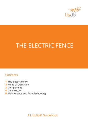
JVA Energizer User Manual4 Parts of the Energizer(M1.5, M3, MB1.5, MB3.0, MB4.5, RSG1, SV2)812347651.2.3.4.5.6.7.8.On/Off Switch (not on M1.5 and M3)Fence OK indicator (red LED)Energizer On and OK indicator (green LED)Rubber O-ring seal between front and back case piecesPower Cable extends from base of caseFence connection terminalEarth connection terminalModel Number6
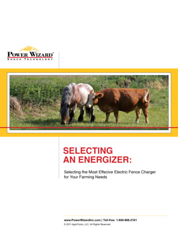
JVA Energizer User Manual4.1Fence ConnectorsEarthFenceterminalterminalFence ConnectionsFence terminal – should be connected to the live wires of the fence.Earth terminal – should be connected to a suitable electric fence earthrod.4.2Energizer LED DisplayThis feature is included on all units.Fence OK LEDEnergizer OK LEDLED displayFence OK red LED – Flashes if fence voltage is good. If it goes out thereis a problem on the fence. (Note: SV2 does not have a Fence OK LED)Energizer OK green LED – Flashes with each pulse to show the unit ison and operating correctly.7
JVA Energizer User Manual5 Important notes – PLEASE READ5.1Electric Fences1. Electric fences are not toys; do not let children play with them.2. Electric fences should only be installed with regard to the relevantStandards and work place health and safety requirements.3. Electric fences should be signed. Warning signs that comply toIEC standards should be prominently displayed on electric fencesat distances specified by the country in which they are installed.4. Electric fences must have an ‘earth’. An electric fence ground isone or more pieces of metal (eg. 1.8m Galvanized earth rods)driven into the earth to a depth of at least 1.2m.5.2Solar Panels1. Mount solar powered energizers so that the solar panel is facingthe noon sun (due north in the Southern hemisphere, due south inthe Northern hemisphere, and at an angle of degree latitude plus10 degrees). If in doubt, confirm with an online solar panel anglecalculator.2. Solar panels need as much direct sunlight as possible, preferablyfull sun all day. Unlike small solar powered items such ascalculators, all JVA solar-powered energizers need directsunlight to generate enough electricity to charge the battery.3. The solar panel also needs to be clean to operate properly. Cleanoff any dust or dirt using a damp cloth.5.3Rechargeable Batteries1. JVA’s MB and SV energizers are compatible with sealed lead acid(SLA) batteries. SLA battery life is shortened considerably if it isa) left in a discharged state or;b) exposed to high temperatures.2. When not in use store the energizer in such a way as to allow thepanel to get as much light as possible, say on a window sill withthe panel facing out. Take the energizer out into sunlight for a fewhours once every month to keep the battery from self discharging.3. WARNINGSLA batteries can produce hydrogen. JVA Energizers that comewith internal batteries are designed to release hydrogen gas toprevent an explosion. Do not take steps to further seal the case.Return the unit for repair if the O-ring seal has become damaged.5.4Other1. Keep any energizers from being immersed in water and out ofextreme heat.2. Be aware that thieves target solar powered items, so a padlockmay be useful in securing the energizer to a fence post.8
JVA Energizer User Manual6 Installation6.1Mounting the Energizer1. Location of Energizer: Ensure the energizer is kept in a dry environment if operating frommains power (M1.5, M3), either indoors or covered. Mount any solar energizer so that the solar panel is facing thenoon sun (due north in the Southern hemisphere, due south in theNorthern hemisphere, and at an angle of degree latitude plus 10degrees).2. Mounting the Energizer The M1.5, M3, MB1.5, MB3.0, MB4.5 and RSG1 can be hung fromthe plastic hanger bracket. There are two different methods for mounting the SV2. These areshown below.Post or Star Picket MountingStar Picket Mounting1. Position the Energizer’sMounting Bracket against thepost.2. Insert the U-Bolts around thepost and into the appropriateholes.3. Slide the flat metal piece overthe bolts and tighten with nuts.Make sure the energizer isstable in its fixed position.Simply slide the bracket over thestar picket.9
JVA Energizer User Manual6.2Connecting to the Fence3. The electric fence requires an ‘earth’. Drive a galvanized earth rod intothe earth. Attach a wire from the Green Earth Connector on the frontof the energizer to the earth stake.4. Connect a wire from the Red Fence Connector on the front of theenergizer to the live wire of the fence.5. Powering the Energizer:Mains Power Source (M1.5, M3, MB1.5, MB3.0, MB4.5): Plug themains power cable (M1.5, M3) or the power adapter (MB1.5,MB3.0, MB4.5) supplied with the energizer into an AC powersource and the energizer. Turn the energizer ON at the On/Offswitch.Battery Power Source (MB1.5, MB3.0, MB4.5 & RSG1): Attachthe battery, red to positive and black to negative battery terminals.For battery choice see specification table 3.2. Turn the energizerON at the On/Off switch.Solar Power Source (MB1.5, MB3.0, MB4.5): It is recommendedthat a solar regulator is used in conjunction with a solar panel anda rechargeable battery (For battery choice see specification table3.2). Please refer to instructions provided with the solar regulatorfor information regarding its setup. Once the solar regulator, solarpanel and rechargeable battery have been configured, connect theenergizer to the rechargeable battery. Red to positive and black tonegative battery terminals. Turn the energizer ON at the On/Offswitch.10
JVA Energizer User Manual7 Operation7.1Electric FencesThe energizer places a very short, safe, high voltage pulse on the fencelive wires approximately once every second. Please be advised thatthere is always a risk associated with any device designed to impart anelectric shock. Do not allow children or elderly persons to touch theenergizer or fence live wires.The high voltage comes from the Fence terminal of the energizer and isconnected to the fence wire or electric fence tape to make a “live” or “hot”wire. Live wires must be insulated (e.g. with insulators) from earth or anyconductive material touching earth (e.g. fence posts).The other connection on the energizer is the ‘earth’ (or ground). Electricfences need ‘earthing’ to complete the circuit: When anything touches thelive wire current will flow from the live wire, through the animal to earthback to the ‘earth’ rod and into the energizer earth terminal.You should not feel a shock from the earth connection or earth rod. If youdo, the ‘earth’ is probably not sufficient. An electric fence ‘earth’ is somemetal in contact with the soil. The more metal in the earth the better, themoister the soil the better. The larger the energizer and the longer thefence the more ‘earth’ is required.For best results place the energizer in the middle of long lines of fence. Acartwheel pattern of farm fences with the energizer positioned centrally ismore effective than a tree arrangement with the energizer at the base ofthe trunk with many branches.The fence and the ‘earth’ can be measured with an electric fence DigitalVoltmeter or Digital Power Probe.7.2Benefits of Electric Fences An electric fence offers a psychological barrier as well as a physicalbarrier. The risk of injury to livestock is lower than with barbed wire fences. Electric fences cost less to install and maintain than conventionalfencing. Users enjoy low maintenance costs because their stock staysoff the fence. Their use is versatile - they can be permanent or portable systems,- they can be arranged in variety of designs to suit needs- they are quick and easy to erect They improve pasture and grazing control. They can improve existing fence life due to less physical pressure. Easy to set up compared to a traditional fence.11
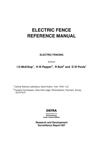
JVA Energizer User Manual7.3 Earth Return SystemThe Earth Return (also called Ground Return) configuration is the mostcommon method for electric fences, particularly smaller fenceapplications like “strip grazing”, due to its lower cost and ease of settingup. The fence live wire(s) are electrified and rely on the dirt to completethe circuit back to the energizer Earth terminal when an animal touchesthe fence.EarthstakeThe electricalcircuit is closedbetween the fenceand the groundwhen the animaltouches the fenceA good circuit requires adequate current flowthrough the ground (through moist soil)7.4 Fence Return SystemThe Fence Return configuration for electric fences is used where the soilcould be too dry to complete the circuit, or the animals are likely to try toforce their way through between the fence wires. In this system earthwire(s) are also run along the fence with the live wire(s) to provide a lowresistance path for the current to return to the energizer. In this system ifthe soil is moist enough it will also function as a return path for the currentwhen the animal touches the live wire, but if the soil is not moist or haspoor conductance, this system will keep your fence effective provided theanimal touches both a live and the earth wire simultaneously.The circuit is closed when theanimal nudges both the live andEarth wires of a fenceThe earthed fence wire providesthe current flow required tocomplete the circuit when theground can not.Due to the dry soil,there is not adequatecurrent flow in theground, and a goodcircuit is not completed12EarthStake
JVA Energizer User Manual8 Common Energizer ProblemsThe most common problems with electric fence energizers are: Moisture and Ants Lightning Blown Fuses (AC units only) Flat batteries8.1Moisture and AntsMoisture and Ants should not be a significant problem for the JVA rangeof energizers as they come in a weatherproof case. Still, where possible,keep the energizer protected from the weather.8.2LightningThe JVA range of energizers is covered with a three-year warranty thatexcludes Lightning. Surge protection components inside the energizer arefitted to reduce the risk of damage by lightning. However, nature iscapable of performing more extremely than can be tested for in thelaboratory; to ensure the wellbeing of your JVA investment for the longterm, it is recommended that a Lightning Protection Kit is installed toprevent lightning damage and possible costly repairs.8.3Flat Batteries (battery units only)The JVA series energizers require a battery that is in good condition torun correctly. The energizer will protect the battery by slowing down andeventually stopping altogether as the battery charge is depleted. For bestresults, check on the energizer at regular intervals. If you are not gettingthe expected life from the battery consider having it checked by an autoelectrician.8.4Changing the Battery (battery units only)Before you start, see “Important Notes” on page 3. If the SV2 stops assoon as the sun sets (and it has been getting 8 hours or more sun a day)or if the RSG1 battery charge does not last more than 5 days (a goodbattery will last 7 days and needs 18 hours to charge), the battery mayneed replacing. The battery is a sealed, lead acid, 6V, 4.2ah battery.Open the unit and read the battery ah and part number before ordering anew one. These may be available from the manufacturer or through thestore where the SV2 or RSG1 was purchased. This type of battery is alsoreadily available through general electronics stores and hardware stores.Notes: The battery must be a rechargeable sealed lead acid battery,never use non rechargeable batteries. The battery should last up to 5 years depending on averagetemperature and usage. Are you sure it needs replacing? Lead acid batteries should be recycled, not sent to land fill.Send it back to the manufacturer if unsure.13
JVA Energizer User Manual If you don’t feel confident in changing the battery, or can’t findthe correct replacement please call us, for a small fee we willbe happy to service your unit.StepsAttention: Take Care: Risk of electrical shock! Risk of fire (See“Important Notes” on page 3)1. Turn the SV2/RSG1 off. Be careful not to press firmly on thefront of the case as this can sometimes turn the unit on.2. Place the SV2/RSG1 face down on a clean working surface.3. Unscrew the six main case screws.4. Turn the unit over so that its face is facing up.5. Pry the front off, note there is an o-ring seal. The seal may bestuck to either or both surfaces. If it comes out of the groovesimply press it back in.6. Disconnect the battery leads. Always disconnect the leads atthe battery terminals NOT the PCB. Do not allow the wiresfrom battery terminals to touch each other.7. Remove the old battery.8. Place the new battery in and secure it in the same way as theoriginal was secured. Do not short the battery terminals.9. Reconnect the battery leads.10. Replace the cover ensuring the o-ring seal is in the grooveand cables are NOT pinched between the lid and case.11. While holding the unit together firmly, turn it back over onto itsface and replace the six main case screws.8.5Dirty Solar PanelsThe solar panel on the SV2 needs to be clean to operate properly andkeep the battery charged. Clean off dust etc. using a damp cloth.14
JVA Energizer User Manual8.6Errors and Error CodesThe JVA energizer may stop and display error codes. The error codes aredisplayed in two places. The first of these is on the Status (red) LED,where it will flash rapidly a number of times. The number of these flashescorresponds to the Error Code. The second place is on the LCD, where itwill display a message.ErrorCode #2Red LEDFlashes234563456LCDDisplayBatterysymbol &“Lo b”“Er 03”“Er 04”“Er 05”“Er 06”7878“Er 07”“Er 08”99“Er 09”1010“Er 10”1111“Er 11”21n/a“Er 21”MeaningFlat Battery: the energizer willrecover and re-start when thebattery is recharged.Charging failureFast PulsingDischarge failureHigh battery: the energizer will restart when the battery voltage issupplied.EEPROM write failureSelf-calibration failure – insufficientoutputSelf-calibration failure – insufficientcapacitor chargeCapacitor failure, charged tooquicklyCalibration error, voltage readingtoo low for fence conditionsOpto-coupler failureFor errors 3 and 5 the energizer will try and recover these three errorswhich are classed as severe errors. This automatic recover process willoccur at 7 minute intervals. Error 4 is classed as a fatal error. Theenergizer will not attempt to automatically restart due to safety concerns.Errors 2 and 6 indicate the battery voltage is either too low or too high.The energizer will restart as soon as the voltage returns to the correctrange. All other errors indicate an internal malfunction.Should the error continue to re-occur, please return the unit to a qualifiedservice centre for repair. There are no user serviceable parts inside theenergizer. All internal fuses will automatically reset themselves.15
JVA Energizer User Manual9 Common Fence ProblemsThe most common problem with electric fences is low voltage on the livewires caused by Insufficient ‘earth’ Shorts on the fenceFor tips on fence construction please see an Electric Fencing Manual.9.1Testing the ‘Earth’.The ‘earth’ is essential to all electric fence systems. Larger energizersrequire more earth rods. Additionally, all energizers require a lowresistance wired connection from the energizer earth terminal to the earthrod.Short the end of your fence to earth by hammering a metal stake into thesoil and connecting this to the live fence wire. Using an electric fence voltmeter or a JVA Electric Fence Fault Finder (do not use a standardmultimeter) check what the voltage is at the earth terminal of theenergizer. In general you should see a reading less than 300 volts(0.3kV).9.2Testing the Fence, Finding ShortsTo test the performance of the fence or find faults on the fence an electricfence voltmeter is essential, and a Digital Power Probe is even better. Aneffective fence will have more than 2 kV (2000 volts).16
JVA Energizer User Manual10 Instructions for installation and connection of electric fencesas required under IEC 60335.2.26This material is copyright of the International Electrical Commission (IEC).10.1 DefinitionsConnecting leadan electric conductor, used to connect the energizer to theelectric fence or the earth electrodeElectric animal fencean electric fence used to contain animals within or excludeanimals from a particular areaElectric fencea barrier which includes one or more electric conductors, insulatedfrom earth, to which electric pulses are applied by an energizer10.2 General requirements for electric fences1. Electric animal fences shall be installed and operated so that theycause no electrical hazard to persons, animals or their surroundings.2. Electric animal fence constructions which are likely to lead to theentanglement of animals or persons shall be avoided.3. An electric animal fence shall not be supplied from two differentenergizers or from independent fence circuits of the same energizer.For any two separate electric animal fences, each supplied from aseparate energizer independently timed, the distance between thewires of the two electric animal fences shall be at least 2 m. If thisgap is to be closed, this shall be effected by means of electrically nonconductive material or an isolated metal barrier.4. Barbed wire or razor wire shall not be electrified by an energizer.5. Any part of an electric animal fence that is installed along a publicroad or pathway shall be identified at frequent intervals by warningsigns securely fastened to the fence posts or firmly clamped to thefence wires.1. The size of the warning sign shall be at least 100 mm x 200mm.2. The background colour of both sides of the warning sign shallbe yellow. The inscription on the sign shall be black and shallbe either: the symbol of Figure 1, or the substance of TAKE CARE – ELECTRIC ANIMALFENCE3. The inscription shall be indelible, inscribed on both sides ofthe warning sign and have a height of at least 25 mm.17
JVA Energizer User ManualFigure 1 – Warning plate symbol4. The energizer earth electrode shall penetrate the ground to a depthof at least 1.2 m.5. Connecting leads that are run inside buildings shall be effectivelyinsulated from the earthed structural parts of the building. This may beachieved by using insulated high voltage cable.6. Connecting leads that are run underground shall be run in a conduitof insulating material or else insulated high voltage cable shall beused. Care must be taken to avoid damage to the connecting leadsdue to the effects of animal hooves or tractor wheels sinking into theground.7. Connecting leads shall not be installed in the same conduit as themains supply wiring, communicating cables or data cables.8. Connecting leads and electric animal fence wires shall not crossabove overhead power or communication lines.9. Crossings with overhead power lines shall be avoided whereverpossible. If such a crossing cannot be avoided, it shall be madeunderneath the power line and as nearly as possible at right angles toit.10. If connecting leads and electric animal fence wires are installednear an overhead power line, the clearances shall be not less thanthose shown in table 3.Power line voltage V Clearance m 1 000 1 000 33 000 33 000348Table 1 – Minimum Clearances from Power Lines18
JVA Energizer User Manual11. If connecting leads and electric animal fence wires are installednear an overhead power line, their height above the ground shall notexceed 3m. This height applies either side of the orthogonal projectionof the outermost conductors of the power line on the ground surface,for a distance of 2 m for power lines operating at a nominal voltage not exceeding1,000 V 15 m for power lines operating at a nominal voltage exceeding1,000 V.10.3 Particular requirements for electric animal fences inAustralia12. A distance of at least 10 m shall be maintained between the energizerearth electrode and any other earthing system connected parts suchas the power supply system protective earth or the telecommunicationsystem earth.13. Electric animal fences intended for deterring birds, household petcontainment or training animals such as cows need only be suppliedfrom low output energizers to obtain satisfactory and safeperformance.14. In electric animal fences intended for deterring birds from roostingon buildings, no electric fence wire shall be connected to theenergizer earth electrode. A warning sign shall be fitted to everypoint where persons may gain ready access to the conductors.15. A non-electrified fence incorporating barbed wire or razor wire may beused to support one or more off-set electrified wires of an electricanimal fence. The supporting devices for the electrified wires shall beconstructed so as to ensure that these wires are positioned at aminimum distance of 150 mm from the vertical plane of the nonelectrified wires. The barbed wire and razor wire shall be earthed atregular intervals.16. Where an electric animal fence crosses a public pathway, a nonelectrified gate shall be incorporated in the electric animal fence atthat point or a crossing by means of stiles shall be provided. At anysuch crossing
1. Electric fences are not toys; do not let children play with them. 2. Electric fences should only be installed with regard to the relevant Standards and work place health and safety requirements. 3. Electric fences must have an 'earth'. An electric fence ground is one or more pieces of metal (e.g. 1.8m Galvanized earth rods) driven into