Transcription
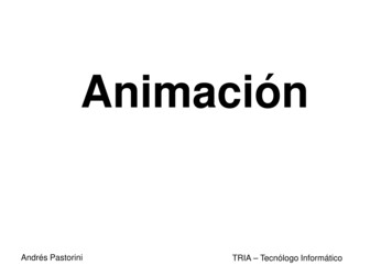
Example-Based Expressive Animation of 2D Rigid BodiesMAREK DVOROŽŇÁK, Czech Technical University in Prague, Faculty of Electrical EngineeringPIERRE BÉNARD, LaBRI (UMR 5800, CNRS, Univ. Bordeaux), FrancePASCAL BARLA, Inria Bordeaux Sud-Ouest, FranceOLIVER WANG, Adobe ResearchDANIEL SÝKORA, Czech Technical University in Prague, Faculty of Electrical Engineering(a) style pairs(b) target sequence(c) stylized sequence(d) stroke appearance transferFig. 1. Given a small set of exemplars consisting of computer-generated and hand-drawn 2D animation pairs (a), our method transfers to a new targetsequence produced by physical simulation (b) both the high-level deformations and fine-scale appearance variations (c) present in the example animations.Optionally, the final appearance of the drawings can be modified by re-synthesizing different stroke textures (d).We present a novel approach to facilitate the creation of stylized 2D rigidbody animations. Our approach can handle multiple rigid objects followingcomplex physically-simulated trajectories with collisions, while retaining aunique artistic style directly specified by the user. Starting with an existingtarget animation (e.g., produced by a physical simulation engine) an artistinteractively draws over a sparse set of frames, and the desired appearanceand motion stylization is automatically propagated to the rest of the sequence.The stylization process may also be performed in an off-line batch processfrom a small set of drawn sequences. To achieve these goals, we combineparametric deformation synthesis that generalizes and reuses hand-drawnexemplars, with non-parametric techniques that enhance the hand-drawnappearance of the synthesized sequence. We demonstrate the potential ofour method on various complex rigid body animations which are createdwith an expressive hand-drawn look using notably less manual interventionsas compared to traditional techniques.CCS Concepts: Computing methodologies Motion processing; Nonphotorealistic rendering;Additional Key Words and Phrases: 2D animation, example-based synthesisACM Reference format:Marek Dvorožňák, Pierre Bénard, Pascal Barla, Oliver Wang, and DanielSýkora. 2017. Example-Based Expressive Animation of 2D Rigid Bodies. ACMTrans. Graph. 36, 4, Article 127 (July 2017), 10 pages.DOI: n to make digital or hard copies of all or part of this work for personal orclassroom use is granted without fee provided that copies are not made or distributedfor profit or commercial advantage and that copies bear this notice and the full citationon the first page. Copyrights for components of this work owned by others than ACMmust be honored. Abstracting with credit is permitted. To copy otherwise, or republish,to post on servers or to redistribute to lists, requires prior specific permission and/or afee. Request permissions from permissions@acm.org. 2017 ACM. 0730-0301/2017/7-ART127 15.00DOI: TIONDespite the recent success of computer-generated animations, traditional hand-drawn approaches often yield more expressive andstylized looks than those produced with the currently available digital tools. However, creating hand-drawn animations is a tediousprocess that requires years of training by an artist and countlesshours of labor. Furthermore, style is a highly personalized concept,and two different artists never animate exactly in the same way. Asa result, example-based stylization has been a long-standing goal incomputer graphics.In this work we focus on rigid bodies, which are particularlychallenging to animate by hand, since multiple objects may collideand rebound in ways that are difficult to plan in advance. Conversely,using physical simulation, computer-based methods can quicklygive rise to rigid body animations with realistic trajectories, butones that lack expressiveness. Our main goal is therefore to combinethe ease of use of computer-simulated 2D rigid body animationswith the expressive qualities of hand-drawn techniques.To accomplish this goal, we have a number of added requirements.First, editability is of paramount importance to animators, and anideal solution should work iteratively, always providing the artistwith the ability to refine the current solution. Second, producingeach hand-drawn frame is time consuming, so a practical examplebased 2D animation system should be able to generalize from avery limited set of artistic inputs, while being able to apply theseedits seamlessly into the dense set of final target frames. Thesetwo requirements make example-based 2D animation out of reachof current data-driven machine learning techniques, due to thescarcity of data (tens of exemplars, rather than tens of thousands),and uniqueness of each style.Instead, our approach is inspired by a workflow that is widespreadamong both traditional and digital animators. A 2D animation isACM Transactions on Graphics, Vol. 36, No. 4, Article 127. Publication date: July 2017.
127:2 Dvorožňák, M. et al.successively produced and refined at three different temporal scales(see Figure 3): the full animation scale at which timing, contactsand trajectories are planed; the pose-to-pose scale, at which theoverall dynamics and deformations between contacts are considered;and the frame-to-frame scale at which the actual drawings withsecondary deformations and precise collisions are produced.At the full animation scale, we split the input computer-generatedsequences based on collision events, and we independently analyzeand stylize each sub-sequence around a hit point, which we calla key pose. Next, for every sub-sequence, we estimate the spatialdeformations of the hand-drawn exemplars before and after thekey pose; these are then transferred using a parametric synthesisalgorithm. Correspondences between sub-sequences are estimatedby leveraging the physical properties of each frame, which ensurespreservation of appropriate stylistic effects given the forces appliedat each frame. The final frame-by-frame drawings are then synthesized from the artist drawings using a non-parametric technique,that captures residual deformations and appearance details.We show that this organization is necessary to capture both thelong- and short-range stylistic choices made by the artist, while producing results that have the desired hand-drawn look and feel. Whentaken as a whole, our method considerably reduces the amount ofwork needed to create the entire sequence by hand.In summary, we present the following contributions: a careful analysis of traditional hand-drawn animations,especially focusing on the correlation between physicalparameters and deformations, a parametric motion synthesis algorithm capable of transferring deformations from exemplars, an example-based non-parametric stylization techniquecapturing the fine-scale drawing appearance.2PREVIOUS WORKWe present prior work related to general stylized computer animation, followed by those driven by physical simulations, and finallyexample-based solutions.Techniques inspired by the principles of animation. From its beginning, one of the goals of computer graphics has been to reproducethe expressiveness of traditional hand-drawn 2D animations, whilereducing the cost and effort of producing it. The fundamental principles of animation, developed from the late 1920’s to the 1930’sat Walt Disney Studio [Thomas and Johnston 1981], play a crucialrole in this expressiveness, and many works have tried to adaptthem to digital animation tools. Lasseter [1987] describes these 2Dprinciples – including squash and stretch, timing and spacing, anticipation and follow-through, arc trajectories and lines of action– and how they can be manually applied by an artist to produceexpressive 3D keyframe animations.Subsequent work has aimed at fully or partially automatizingthose effects. Wang et al [2006] describe a simple temporal filterthat produces anticipation and follow-through as well as squashand-stretch deformations by delaying parts of an existing animation,represented by 2D polygonal shapes or motion captured (MoCap)data. Lee et al. [2012] obtain similar effects on segmented objects ina video by relating a set of representative 2D deformations to theACM Transactions on Graphics, Vol. 36, No. 4, Article 127. Publication date: July 2017.modal analysis of the object motion. Focusing on 3D skeletal animation, Noble and Tang [2006] present a tool to automatically bendthe limbs of a character following lines of actions or arcs. On theartistically controllable side, Li et al. [2003] present a sketching interface that allows a user to guide the deformation of both the inputanimated skeleton and surface mesh to improve the expressivenessof MoCap data. Recently, several 2D sketching systems [Kazi et al.2014a,b, 2016; Xing et al. 2016] have been developed to simplify theproduction of dynamic illustrations, reproducing most principlesof character or special effects animation. However these principlesare essentially encoded as scripted deformations or animated loopstriggered by events, and unlike our work are not tailored to thespecific style of a given artist.Physics-driven approaches. Physical simulation is a convenientway to automatically animate a large number of 2D or 3D bodies,but expressiveness of the resulting motion is restricted by the degreeof complexity modeled by the physical system. For instance, it iscommon to restrict the simulation to rigid bodies for computationalefficiency, while traditional hand-drawn animated objects moreoften resemble deformable bodies governed by exaggerated physicallaws. To enhance basic 3D simulations, multiple works [Chenneyet al. 2002; Garcia et al. 2007; Haller et al. 2004] derive automaticprocedural rules to generate squash-and-stretch and temporal effectsbased on motion parameters (velocity, acceleration, etc.) but suchmethods have limited art-directability.To allow artistic control, the spacetime [Witkin and Kass 1988]and dynamic [Barzel and Barr 1988] constraint formulations castphysical simulation as a constrained optimization problem. Throughthose constraints, the artist can direct the simulation to act as aphysically-plausible interpolation mechanism between key-poses.Bai et al. [2016] leverage this idea to build a 2D animation systemthat combines keyframing of local deformations with physical simulation for powerful inbetweening. Although this approach allowsan unprecedented level of artistic control and manages to reproducemany of the principles of animation, it requires the user to specifycontrol handles, which are constrained and unnatural to use whencompared to simply drawing frames, in particular when the artistdesires a precise control over shape outlines.Example-based methods. This family of techniques provides anatural and intuitive interface, where examples are used to capturethe style and intent of an artist. Such approaches have alreadyproduced impressive results for static images and videos, eitherusing non-parametric texture synthesis [Bénard et al. 2013; Fišeret al. 2016; Hertzmann et al. 2001; Lu et al. 2012] or more recentlywith neural networks [Gatys et al. 2016]. Yet these methods aremostly restricted to appearance stylization, leaving motion largelyuntouched.There are some exceptions, such as Bregler et al. [2002] whopropose to capture and re-target motion from existing cartoon animations by combining a global affine deformation with drawingsinterpolation using a key-shape model. Jones et al. [2015] followsa similar approach, connecting the navigation in a simplicial complex [Ngo et al. 2000] with events of a 2D physical simulation. Posespace interpolation can produce impressive results, but the quality
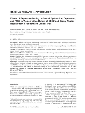
Example-Based Expressive Animation of 2D Rigid Bodies 127:3Source sequence F SStyle exemplars F ETarget sequence F TStylized sequence F OFig. 2. Stylization analogy setup — given a set of frames F S coming from reference 2D rigid body source animations, corresponding hand-animated exemplarsF E , and a new target animation F T , the synthesis algorithm relates physical parameters in F S and F T to produce the output stylized sequence F O thatresembles F E . (Animations are depicted with onionskins, colored from green to blue according to frame numbers.)of the output is highly dependent on a good choice of the key-shapeswhich an artist has to select and organize manually beforehand.To guide or enrich 3D simulations, example-based approachesaugment the simulated objects with examples of desirable deformations [Coros et al. 2012; Jones et al. 2016; Koyama et al. 2012; Martinet al. 2011]. In those approaches, however, exact correspondencesbetween deformation exemplars are known beforehand and only asimple parametric deformation with limited number of degrees offreedom is used. Even though this setting may be natural for digital3D artists, it is again limited and constraining for traditional 2Danimators.Closest to the traditional animation pipeline, Xing et al. [2015]present an interactive system for computer-assisted 2D animation.It combines discrete texture synthesis with an as-rigid-as-possibledeformation model to predict and interpolate drawings based onthe current and previous frames. This approach is convincing forframe-by-frame animation, but the spatio-temporal locality of theanalysis makes it unsuited for pose-to-pose planning. Since theinterpolations are solely based on the past drawings using localaffine transformations, the predicted motion and deformations tendto be unnatural and cannot easily be edited, unless the artist drawsmost intermediate frames.3OVERVIEWSimilar in spirit to Image Analogies [Hertzmann et al. 2001], ouralgorithm transforms a target 2D rigid body animation F T into anoutput stylized version F O using an example-based transformationdefined by a set of source sequences F S and a corresponding setof hand-drawn exemplars F E (Fig. 2). Sequences F S and F T canbe computer-generated using, e.g., physical simulation. The styleexemplars F E are created by an artist digitally or physically, byredrawing a small subset of the source frames F S . In one application,the untouched frames of F S can be added to F T , in which case ourmethod can be seen as an interactive style propagation tool. This isshown in the accompanying video where the artist first draws over afew frames, sees the intermediate result, identifies parts which havenot been successfully stylized, provides additional examples, anditerates this procedure until she is satisfied by the stylized result.The key challenge here comes from the fact that F T will typicallynot contain sub-sequences exactly like those in F S , and thus stylizedframes from F E cannot simply replace original rigid frames in F T .To tackle this problem, we take inspiration from guidelines in traditional 2D animation books [Thomas and Johnston 1981; Williams1. Full animationKeys2. Pose-to-pose3. Frame-to-frameFig. 3. Three scales hierarchical decomposition of the animation process,based on [Williams 2001, p.67].2001], especially from Richard Williams’ hierarchical decomposition of the animation process (see Figure 3). We identify three mainstages or temporal scales: (1) the full animation scale, at which timing and spacing are planned by choosing the key events, (2) thepose-to-pose stage, at which the main dynamics and deformationsare defined between two key poses by drawing “extremes” and“breakdowns”, and (3) the frame-to-frame scale, corresponding tofinal straight-ahead “runs” (or drawing passes) during which subtlevariations and details are added.Each of the three stages need to be analyzed for transferringthe style of a hand-drawn animation and our method thus followsthis organization. First, timing and spacing are specified by theinput sequences F S and all animations are subdivided into overlapping sub-sequences around key events (Section 4). The style pairsF S : F E are then decomposed into a coarse geometric deformationD and a fine-scale “residual” stylization R (Section 5.1). Our aim isto transfer both D and R to the target sequence F T . For each targetsub-sequence independently, a new parametric deformation is synthesized by selecting and blending together multiple deformationsD coming from similar sub-sequences of the style pairs (Section 5.2).Finally, sub-sequences are blended together, the fine-scale details arereintroduced on a frame-by-frame basis by morphing the residualchanges R, and the appearance of individual strokes is changed tohave a desired look of particular artistic media (Section 6). In thefollowing, we use the classical “bouncing ball” animation to illustrate the various steps of our algorithm; results on more complexsequences (collisions between objects, bouncing square, texturedobjects) are shown in Section 7 and the supplemental material.ACM Transactions on Graphics, Vol. 36, No. 4, Article 127. Publication date: July 2017.
127:4 Dvorožňák, M. et al.F1F2N1Fe1M 1,2TIMING AND SPACINGThe source F S and target F T input sequences consist in 2D rigidbody animations produced using physical simulation. In practice, weuse Box2D [Catto 2007]. Similar to prior work [Kazi et al. 2016], anarbitrary target rigid body is represented by its proxy geometry, e.g.,bounding circle, square, or any other closed polygon. In additionto images, the simulation generates, at each frame and for eachobject, a set of physical parameters including the object velocity vand the rotation angle α around the object centroid with respect tothe local trajectory frame. The timing and spacing are dictated bythe simulation; the artist draws over existing frames, establishingone-to-one temporal correspondences between F S and F E .The simulation also identifies frames at which semantically important events E occur, such as contact points or collisions. Followingthe guidelines of Richard Williams [2001], these frames representkey poses. Analyzing the hand-drawn exemplars F E , we also observed that those frames, and their immediate neighbors in time,are the ones most stylized by the artist, whereas distant frames areless modified. In addition, we noticed that the physical parametersalong the simulated trajectories before and after these key eventslargely influence the artist’s stylization choices, e.g., the magnitudeof the deformation.These observations motivate us to subdivide F S , F T and F E intoa set of smaller overlapping sub-sequences FiS , FiT and FiE aroundevery key event ei of E. Each sub-sequence Fi contains Ni consecutive animation frames and overlap with the next sub-sequence onMi,i 1 frames. As shown in Figure 4, the overlapping part betweentwo events resides at frames where there are no abrupt changes inphysical parameters and moderate artistic stylization, making themmost suitable for stitching.5POSE-CENTERED DEFORMATIONSAt this stage, we consider each sub-sequence independently, and focus on the coarse deformations used by artists when hand-animatingrigid bodies to reproduce effects described in the principles of animation (squash-and-stretch, arc trajectories, lines of action). Residualdeformations and appearance variation that are not captured by thiscoarse deformation will be reintroduced in Section 6.5.1feDfrD 1 e2Fig. 4. Decomposition into sub-sequences — an input sequence F is subdivided into sub-sequences (F i ) of N i frames around key events (e i E)with an overlap of M i,i 1 frames with the following sub-sequence.4fs(a)(b)Fig. 5. Deformation analysis — (a) The parametric deformation D is estimated using as-rigid-as-possible registration between the source f s andexemplar f e frames. (b) The residual frame f r is then computed by applyingthe inverse deformation D 1 on f e .deformable grid matching, we use a single quadratic transformationas in Müller et al. [2005]. The main advantage of this quadraticmodel is that besides shear and stretch, it also captures twist andbending modes (see Figure 6) which better represent the larger scopeof deformations used in traditional animation.The output of the image registration phase consists of 12 parameters describing the corresponding quadratic deformation that warpspixels p (x, y) from the source frame f s FiS to match pixelsp 0 (x 0, y 0 ) of the stylized frame f e FiE :x 0 a 11x a 12y q 11x 2 q 12y 2 m 1xy t 1(1)y 0 a 21x a 22y q 21x 2 q 22y 2 m 2xy t 2Written in matrix form: p0 A Q m{z t p̃}(2)D(x, y, x 2 , y 2 , xy, 1) where p̃ is p expressed in extended homogeneous coordinates, and D is a quadratic transformation matrixcomposed of affine A, purely quadratic Q, mixed m, and translationt parts: A 5.2a 11a 21a 12a 22Q q 11q 21q 12q 22m m1m2t t1.t2Parametric deformation synthesisBased on traditional hand-drawn animation resources as well asour own observations and discussions with 2D animators, we makethe key hypothesis that deformation is closely tied to motion. Asa result, to perform the deformation transfer, we search for correspondences between source FiS and target F jT sub-sequences usingphysical parameters that describe the frame’s motion (velocity, trajectory orientation, and the object’s rotation), and we assume thatthe matching sub-sequences should undergo similar deformationsD as the source ones.Parametric deformation analysisFor each frame of a style pair FiS : FiE , we first estimate a coarseparametric deformation D (see Figure 5(a)) using the registrationalgorithm of Sýkora et al. [2009] which aligns bitmap images withan as-rigid-as-possible grid deformation. However, instead of theACM Transactions on Graphics, Vol. 36, No. 4, Article 127. Publication date: July 2017.affine Aquadratic Qmixed mFig. 6. Visualization of the 10 modes defined by the quadratic deformationof Müller et al. [2005].
Example-Based Expressive Animation of 2D Rigid Bodies 127:5Source-target sub-sequence matching. Practically, we define thefollowing difference metric between a source sub-sequence FiS anda target sub-sequence F jT :Diff(FiS , F jT ) λ vel Vel(FiS , F jT ) λ dir Dir(FiS , F jT )(3) λ rot Rot(FiS , F jT ),f 2ef 1ef 3ef 2sf 1sD1D2w2w1f 3sD3w3D̂where weights λ vel , λ dir , λ rot are used to balance the influence ofindividual terms: Vel(FiS , F jT ) measures the difference between rigid body centroidvelocities v:Vel(FiS , F jT ) NÕn 1 vn (FiS ) vn (F jT ) 2 ,(4) Dir(FiS , F jT ) penalizes discrepancy of the trajectory orientation δ :Dir(FiS , F jT ) NÕn 1 δn (FiS )δn (F jT ) 2 ,(5)where computes the smallest difference between two angles, Rot(FiS , F jT ) accounts for differences in the rotation α of the rigidbody around its centroid:Rot(FiS , F jT ) NÕn 1 α n (FiS )α n (F jT ) 2 .(6)When computing the metric we assume that both sub-sequencesare centered at a key event and have the same number of framesN . This can be done by resampling the original trajectories to haveequidistant samples according to their arc length. The longest subsequence is trimmed to have the same length as the shortest one.Deformation blending. Since it is unlikely that any source subsequence perfectly matches a given target sub-sequence F jT , weretrieve K nearest neighbor sub-sequences F 1S . . . F KS instead of asingle one. For each frame in F jT , we then compute its stylizedversion as a combination of K quadratic transformations D1 . . . DKfrom the K best corresponding frames in source sub-sequences usingweights w 1 . . . w K proportional to their similarity:1/Diff(FkS , F jT )w k ÍK, k [1 . . . K]S Tκ 1 1/Diff(Fκ , F j )where normalization is used to obtain the partition of unity. See Figure 7 for an overview of this blending scheme (with K 3) whichadds robustness to the matching process and gives more stableresults than simply using the single best match (K 1).To perform a meaningful interpolation of the rotational part of thetransformation, the affine part A of the matrix D is factorized usingpolar decomposition [Higham and Schreiber 1990] into a linearstretch U (not used directly) and a rotation matrix R α , from whichthe rotation angle α arctan(r 11 /r 21 ) is extracted. A weightedblend is computed on α 1 . . . α K :α̂ w 1 α 1 . . . w K α K(7)Fig. 7. Blending quadratic deformations D — individual quadratic deformations D1, D2, D3 estimated from the source frames f 1s , f 2s , f 3s and theircorresponding stylized counterparts f 1e , f 2e , f 3e are blended together usingthe weights w 1, w 2, w 3 to obtain the resulting quadratic deformation D̂.where computes a weighted average of circular quantities. Theremaining coefficients of rotation-free quadratic transformationsD10 · · · DK0 are similarly computed:D̂ 0 w 1 D10 . . . w K DK0(8)where D 0 R -α D. Finally, the blended quadratic transformationmatrix D̂ is constructed from α̂ and D̂ 0 :D̂ R α̂ D̂ 0(9)Data augmentation. To generate plausible results even when theglobal orientation or scale of the target trajectory departs considerably from the available exemplars, we enrich the set of sourceanalogies by scaling, rotating, and flipping the input sequences. Wecan directly extract the set of required rotation angles γ by analyzing the target simulation. Based on our experiments, we alsouse 5 scaling factors ρ between 0.2 to 1 and allow symmetries withrespect to the vertical axis only (to preserve gravity effects). Forrotationally symmetric objects of order n, we modify the operator in a way that it outputs zero difference for angles k 360n where theapperance of the rotated object is the same. For the circle the orderof rotational symmetry is infinite so instead we set λ rot 0.The drawback of the augmentation is that it may lead to incorrectstylizations when the source exemplars are far from the target motion. For example, a source exemplar corresponding to a small jumpwill not be equivalent to a source exemplar with a higher jump. Toaccount for this, we dampen the resulting quadratic transformationD̂ by computing a weighted blend of D̂ with the identity matrix Iusing weight ξ , proportional to the ratio of the average source andtarget velocities:ÍNvn (FiS )D̂ ξ D̂ (1 ξ ) I with ξ Ín 1(10)NTn 1 vn (F j )However, if rotational invariance is not (even approximately) satisfied, orientation augmentation cannot be used, and the artist willneed to prepare a set of additional exemplars corresponding to thecorrect rotational motion.ACM Transactions on Graphics, Vol. 36, No. 4, Article 127. Publication date: July 2017.
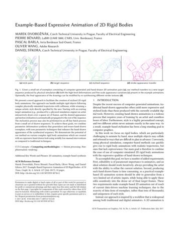
127:6 Dvorožňák, M. et al.f 1rf 2rfˆ1rD̂f 3rfˆ3rD̂w2w1fˆ2rD̂w3n-way morphfˆrFig. 8. Synthesis of fine-scale details R — the synthesized quadratic deformation D̂ is applied to individual residual frames f 1r , f 2r , f 3r producingtheir deformed counterparts fˆ1r , fˆ2r , fˆ3r . Those are then blended togetherusing n-way morphing [Lee et al. 1998] to produce the resulting frame fˆr .6FRAME-BY-FRAME STYLIZATIONAlthough the parametric transformations D capture most of thedominant global deformations, there are still small residual deformations and appearance variations R (e.g., sketch lines of the drawings)which cannot be simply described by the quadratic deformationmodel. These residual changes represent a very important part ofthe stylization, as they provide much of the uniqueness of traditionalhand-drawn, as opposed to computer-generated animation.Extraction of the residual. Due to the parametric deformationmodel, extracting R from the source exemplars is straightforward.We compute and store the residual frames in FiR by “rectifying”the example frames in FiE using the inverse transformation to thedeformation D estimated in Section 5.1 (see Figure 5(b)).Contact points adjustment. Our synthesis process does not guarantee that the resulting animation preserves the alignment withobstacles at contacts. This issue bears resemblance to the foot stepdetection/correction mechanism used when blending motions inskeletal animation. Yet our problem is simpler since we know theposition of contact points; we can easily verify whether the spatialalignment with obstacles is preserved. If not, we simply shift orslightly rotate the synthesis result so that it aligns perfectly withthe obstacle at collision time. To estimate the corresponding translation and rotation we use again image registration algorithm ofSýkora et al. [2009]. To avoid ambiguity in translation along theobstacle during the registration, we restrict the centroid of the synthesized drawing to move perpendicularly to (along the normal of)the nearest obstacle.Texturing. We support two options to apply a texture inside thedeformed drawings. The first one takes as input a static imagewhose content is constant during the full sequence. This image isfirst rotated according to the target sequence orientation, then it isregistered with every residual frame fir using [Glocker et al. 2008],and finally replaces those during the subsequent fine-scale synthesissteps (see Figure 13(c)). If the content of the texture varies in time,the artist needs to provide two versions of the style exemplar: oneonly showing the outline of the drawing and another with the fulltexture (see Figure 17). The former is used for quadratic registrationwhereas the latter is copied during the frame-by-frame synthesis.Stroke appearance transfer. To offer additional artistic controls,we optionally allow the stroke appearance to be re-synthesized byexemplar using StyLit [Fišer et al. 2016]. This can also help suppressresampling artifacts that may occur when applying the quadraticand free-form deformations. In practice we replace the complexillumination-based guidance with a simple gray-scale guiding channel G that softly demarcates positions of strokes in the source andin the target image (see Figure 9).(c)Synthesis of fine-scale details. For a given target frame in F jT , wenow want to re-introduce the residual variations to the synthesizedparametric transformation D̂. As illustrated in Figure 8, we d
Example-Based Expressive Animation of 2D Rigid Bodies 127:3 Source sequence FS Style exemplars FE Target sequence FT Stylized sequence FO Fig. 2. Stylization analogy setup — given a set of frames FS coming from reference 2D rigid body source animations, corresponding hand-animated exemplars FE, and a new target animation FT, the synthesis algorithm relates physical parameters in FS and .