Transcription
A&A 594, A90 (2016)DOI: 10.1051/0004-6361/201527612Astronomy&Astrophysicsc ESO 2016Transient effects in Herschel/PACS spectroscopyDario Fadda1,2,? , Jeffery D. Jacobson3 , and Philip N. Appleton3123Instituto de Astrofisica de Canarias, 38205 La Laguna, Tenerife, Spaine-mail: darioflute@gmail.comUniversidad de La Laguna, Dpto. de Astrofísica, 38206 La Laguna, Tenerife, SpainNASA Herschel Science Center – California Institute of Technology, MC 100-22, Pasadena, CA 91125, USAe-mail: [jdj;apple]@ipac.caltech.eduReceived 21 October 2015 / Accepted 18 January 2016ABSTRACTContext. The Ge:Ga detectors used in the PACS spectrograph onboard the Herschel space telescope react to changes of the incidentflux with a certain delay. This generates transient effects on the resulting signal which can be important and last for up to an hour.Aims. The paper presents a study of the effects of transients on the detected signal and proposes methods to mitigate them especiallyin the case of the unchopped mode.Methods. Since transients can arise from a variety of causes, we classified them in three main categories: transients caused by suddenvariations of the continuum due to the observational mode used; transients caused by cosmic ray impacts on the detectors; transientscaused by a continuous smooth variation of the continuum during a wavelength scan. We propose a method to disentangle these effectsand treat them separately. In particular, we show that a linear combination of three exponential functions is needed to fit the responsevariation of the detectors during a transient. An algorithm to detect, fit, and correct transient effects is presented.Results. The solution proposed to correct the signal for the effects of transients substantially improves the quality of the final reductionwith respect to the standard methods used for archival reduction in the cases where transient effects are most pronounced.Conclusions. The programs developed to implement the corrections are offered through two new interactive data reduction pipelinesin the latest releases of the Herschel Interactive Processing Environment.Key words. methods: data analysis – techniques: spectroscopic – infrared: general1. IntroductionThe Herschel Space Observatory (Pilbratt et al. 2010) completedits mission on April 29, 2013 after performing a total of 23 400 hof scientific observations during almost 4 years of activity (1446operational days). One of the most used instruments aboardHerschel was the PACS spectrometer (Poglitsch et al. 2010). Approximately one quarter of the total scientific time was devotedto PACS spectroscopy. Although most of the observations wereperformed in the standard chop-nod mode, a substantial fraction (30% of the observations, corresponding to the 25% of thetotal spectroscopy time) used two alternative modes. The wavelength switching mode was released to users after the start of themission to allow PACS spectrometer observations to be made incrowded fields where chopping was not possible. A year later,this mode was replaced by the so-called unchopped mode. Bythe end of the Herschel operation mission, this mode was usedfor approximately one-third of all PACS spectroscopic observations. The primary focus of this paper is to describe an optimalway to reduce data taken in the unchopped mode.The PACS spectrometer was able to observe spectroscopically between 60 µm and 210 µm using Ge:Ga photo-conductorarrays. This type of detectors suffers from systematic memory effects of the response which can bias the photometry ofsources and increase the noise in the signal. Such effects havebeen documented and studied for similar detectors on previousspace observatories such as ISOCAM (Coulais & Abergel 2000;Lari et al. 2001) and MIPS (Fadda et al. 2006, Fig. 17).?Moving to the SOFIA Science Center (USRA).In this paper we briefly review the observational modesof the PACS spectrograph and the data reduction techniques.We describe how the unchopped mode is particularly sensitiveto sudden changes in incident flux, and cosmic ray glitches,which cause memory effects in the detector responses. Finally,we introduce the technique used to correct most of these effects, and show a few selected examples. The methods andsoftware described in the paper are now implemented in theHerschel Interactive Processing Environment (HIPE1 ; Ott 2010).The comparisons presented in the paper are between the archivedSPG (standard product generation) products, generated withHIPE 14.0 and calibration data version 72, and our pipeline inHIPE 15.2. The PACS spectrometerWe recommend reading Poglitsch et al. (2010) and the PACS observational manual for a detailed description of the PACS spectrometer. As a way to introduce some terminology used in thepaper, we give here a concise description of the instrument andhow it works.The PACS spectrometer was an IFU (integral field unit) composed by a matrix of 5 5 spatial pixels (spaxels or spacemodules) covering a field of 470 470 square arcminutes. The5 5 pixel image passed into an image slicer, which rearrangedthe 5 5 two-dimensional image into one-dimension (1 25),which then fed a Littrow-mounted diffraction grating where ticle published by EDP SciencesA90, page 1 of 14
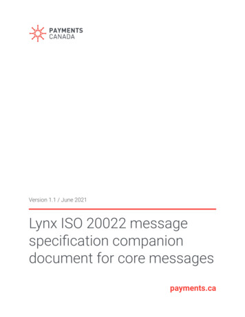
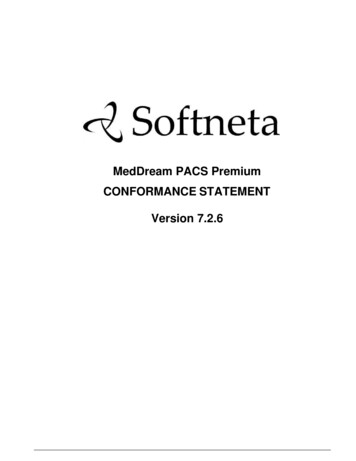
A&A 594, A90 (2016)3. Observational modesSpectroscopic observations consist of a calibration block followed by a series of science blocks. The calibration block isperformed when the telescope is slewing to reach the targetand involves rapid chopping between the two internal reference black-bodies. The science target is then observed in one ormore bands using either the chop-nod or the unchopped observational mode. The chop-nod mode is used for isolated sourcesand involves the continuous chopping between target and anoff position. The unchopped mode is used to observe crowdedfields or extended sources. It consists of a staring observationof the science target followed by an observation of the reference off position by moving the telescope. This mode replacedthe wavelength-switching mode used for earlier observations. Instead of chopping, the wavelength switching used a wavelengthmodulation to move the line on the detector array by a wavelength equivalent to the FWHM of the line. This allowed thedifferential spectrum to be measured, but it was found to be inefficient during the verification phase and deprecated. Observations in unchopped mode suffered from detector transient effects.A90, page 2 of 14 10.58Dec [degs]operated at 1s, 2nd, and 3rd order. The first order (red) andsecond or third order (blue) were separated with a dichroicbeam-splitter, where the spectra were re-imaged onto separatedetectors. The wavelength range covered is 51–105 µm for theblue (choice of 51–73 and 71–105 µm for the 3rd and 2nd order)and 102–220 µm for the red, respectively.The dispersed light was detected by two (low and highstressed) Ge:Ga photo-conductors arrays with 25 16 pixels. Inthe following we call spectral pixels the individual pixels of thetwo arrays. We call module or spaxel (from spatial pixel) the setof 16 spectral pixels corresponding to the dispersed light from asingle patch of 9.4 9.4 square arcseconds on the sky.Since the instantaneous wavelength range covered by16 spectral pixels is small ( 1500 km s 1 for many observations), the grating was typically stepped through a range of grating angles during an observation. This operation is referred asa wavelength scan. During a standard observation, the desiredwavelength range is covered by moving the grating back andforth. These movements are called up- and down-scans, sincethe wavelength seen by a single spectral pixel first increases andthen decreases as the grating executes a scan first in one direction, and then back.The other mobile part of the system is the chopper which liesat the entrance to the whole PACS instrument. This is a mirrorwhich allows the IFU to point at different parts of the sky. Instandard chop-nod mode, the chopping mirror is used to alternatively point rapidly to the source and then a background position, while maintaining the same telescope pointing. The largestchopper throw available is 6 arcmin, which is a limitation of thechop-nod mode. If the chopper mirror is moved to larger angles,it can access two internal calibrators (BB1 and BB2) which areused for calibration during the slew to the target source.Since the mirror is passively cooled, the emission of the telescope is significant, and typically dominates the total signal. Forinstance, in the red, the emission seen by a given pixel at 120 µmis around 300 Jy. This high telescope background level, althoughnot generally desirable in IR astronomy, has the advantage thatit helps to mitigate transient effects in the detectors by helping tokeep the signal level constant at the detectors. A second propertyof the dominant telescope signal is that it is always present, andcan be used as a relatively constant reference flux. This propertycan be positively exploited in the analysis of these PACS data. 10.62Chop 2Nod BOffSlewChop2Chop 1On 10.66 10.70Nod AChop1310320330340Off350Time [s]Fig. 1. Example of chop-nod observation footprints (top), and observedposition projected on the sky (bottom). In the first nod, the detector alternates between two optical paths to observe the object and the background. These paths have slightly different telescope background signals. In the second nod, the optical paths are inverted after slewing thetelescope. By adding the two object-background differences, it is possible to remove the effects of the different telescope background levels.This paper is directed at ways of solving some of these problemswithin the HIPE software.3.1. Chop-nod modeThe standard way to observe with the PACS spectrometer wasthe chop-nod mode. During a wavelength scan, the chopper modulates between an on-source and off-source position. In this way,any variation of the response slower than the chopping time canbe subtracted using the off-source constant reference. However,since the on- and off-source chop signals follow different opticalpaths through the telescope, the observed telescope backgroundemission is slightly different in the two chop positions. To remove this effect, the telescope is nodded. In the left panel ofFig. 1 we show the first nod position (nod B) when the sourceis observed in the chop 2 position. The right-hand panel showsthe situation after a small slew which places the source in chopposition 1 where the observation is repeated (nod A). The opticalpaths used to observe source and off-field are inverted so that theaverage of the source minus off signals is largely unaffected bythe different telescope backgrounds.Two types of submodes are defined in the chop-nod mode.In the case the observation involves an unresolved line, the linechop-nod mode defines an optimal way to observe the line andthe surrounding continuum. If a larger wavelength range is required, the range chop-nod mode can be used to manually enterthe range of wavelengths to be scanned by the grating.
D. Fadda et al.: Transient effects in Herschel/PACS spectroscopyThe data reduction is done on each individual pixel. The simplest reduction technique uses the calibration block to computethe average response during the observation. The response is defined for each pixel as the ratio between the measured and expected signal from the internal calibrators which was measuredin the laboratory. The measured signal is composed of the telescope background (T A and T B in the two chopping positions),source flux (s), and dark (d) signal. The telescope background isdominated by the emission of the primary mirror, and dependson the temperature of the spot which is seen by the detector.Because of differential variations in the mirror temperature, andits emissivity with position on the mirror, the different chopperpositions tend to see differing degrees of telescope background.Although, during a given observation, the overall temperatureof the mirror changed slowly, it was measured to vary due tochanges in illumination of the spacecraft by the Sun on longertimescales than a single observation.For the measured signal C, in V/s, in a chop-nod observationwe have:C1 (T A d s) · R(t) C2 (T B d) · R(t)C10 (T A d) · R(t)C20 (T B d s) · R(t)(1)for the two chop positions in the first (C1 and C2 ) and secondnods (C10 and C20 ), respectively. Here R(t) ρλ · r(t) is the product of the relative spectral response function (RSRF) ρλ and theresponse function r(t) (V s 1 Jy 1 ) which can vary with time.T A and T B correspond to the signal detected from the telescopebackground at the chopper positions A and B, respectively.The simplest technique consists in estimating the signalsource by computing the differential signal, ŝ, between the chopping positions and combining the nods:ŝ [(C1 C2 ) (C10 C20 )]/(2 · ρλ · rCB ),[Jy](2)where rCB hr(t)i is the average response estimated from thecalibration block. As we can see, the method works if r(t) isapproximately constant during a chopping period (1 s) so that thesubtraction cancels the effect of a transient. This approach wasused by the so called SPG (standard product generation) pipelineto populate the Herschel Science Archive (HSA) for chop-nodobservations2 until recently.Since SPG 13, an alternative approach exploiting the knowledge of the telescope background is used. This technique doesnot require the application of the RSRF and response correctionssince it uses the ratios between the observations in the two chopping directions. Nevertheless, the accuracy of the results dependson the knowledge of the mean telescope background. Also, ratios introduce more noise in the final signal with respect to thestandard reduction.In formulae, if we define normalization as:N C1 C2 C10 C202s 0,0 C1 C2 C1 C2 T A T B 2d s(3)the signal normalized to the average telescope background canbe expressed as:sNs ·hT i d (T A T B )/2 d 1 N/2(4)The source flux can be therefore derived by multiplying thenormalized signal by the telescope background (dark science-archiveThis method frees the result from the effects of the variable response although it requires the knowledge of the dark. SincePACS has no shutter, the dark was measured in the laboratorybefore the launch of Herschel. It is not known with great accuracy although its value is negligible with respect to the telescopebackground. The telescope background was derived in flight bycalibrating the emission of the mirror with observed spectra ofbright asteroids.3.2. Unchopped modeAt the end of the verification phase, the wavelength switchingmode (see Poglitsch et al. 2010) was released3 and used in a fewkey programs. Several disadvantages became apparent with thismode during its early use, leading to its replacement with theunchopped mode. For example, by construction, the continuumof the source could not be measured. Moreover, only observations of unresolved lines could be measured correctly. Asymmetric lines or lines broader than the wavelength switching interval were found to be difficult to recover. For large wavelengthranges, SED shape variations can lead to peculiar baselines inthe final differential spectrum. This made observations over largewavelength ranges challenging. Finally, the rapid switching ofthe grating between two distant wavelength positions createdmechanical oscillations which required a long time to damp.This effect was more severe in space than during ground testing, leading to longer time intervals between useful observational samples and thus preventing an efficient removal of rapidresponse variations.It appeared clear that performing a slow grating scan whilestaring at an object, followed by a similar observation pointedto an off position, yielded superior results compared withwavelength-switching. This unchopped mode had the advantageof allowing large wavelength range scans, such as far-IR SEDsof confused or extended regions. Unlike the chop-nod mode,where the two chopper positions sample different optical pathsand therefore different mirror temperatures, in the unchoppedmode the optical paths used for on- and off-source observationsare the same. Therefore, the mirror temperature in the on- andoff-source are exactly the same. Moreover, in the case of chopnod, the footprint of the detector on the sky rotates slightly between the two chop positions (see the PACS observer manual,Fig. 4.7). The effect, though small, is worse for the larger chopper throws. This means that in the two nod positions, the onlyspaxel seeing precisely the same part of the source is the centralone. Spaxels further from the center become successively mismatched in the two nods. So, the reduction works best for thecentral spaxel. This problem does not exist for the unchoppedmode because the observation of the on- and off-positions aremade with a fixed central chopper position.The unchopped line and range modes were released onSeptember 2010, superseding the previous wavelength switchingmode4 . A specific unchopped mode for bright lines was releasedon April 20115 SWaveSwitching ReleaseNote seStatus/PACSUnchopped ReleaseNote ic/PacsAotReleaseNotes/PACS UnchoppedReleaseNoteBrightLines 15Apr2011.pdf Note that all the AOT releasenotes will be provided on the Herschel Legacy Library website startingfrom 2017.A90, page 3 of 14
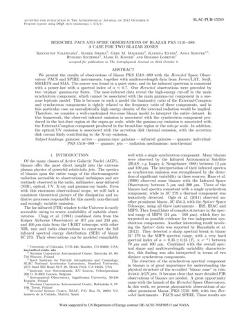
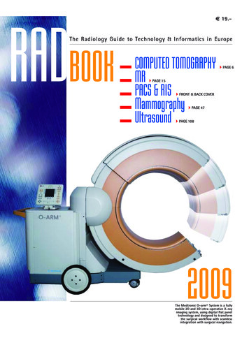
A&A 594, A90 (2016)10BB192.5BB1Flux [V/s]82.0BB276Calibration 52Calibration blockPreviousvaluesObsBlue arrayRed array10.00Flux / Flux BB210203040 5060708090 100 110 1201.101.101.051.051.001.000.950.900.85Red array304050607080203040 5060700.95BB1BB2201090100110Time [s]8090 100 110 1200.90BB1BB20.85Blue array2030405060708090100 110Time [s]Fig. 2. Transients affecting the calibration block for the red (left) and blue (right) arrays. During the calibration block, the detectors see alternativelythe two blackbodies (top panels). Since the initial flux is significantly different from the fluxes of the internal blackbodies, a strong transient occursduring the first minute of the observation. The signals normalized to the median values of each blackbody (bottom panels) show how the sametransient affects the fluxes from the two blackbodies (blue and red lines). The transient effect is more pronounced for the red array.In unchopped mode, a complete wavelength scan is done firston the on-source (hereafter ON) position and then later on a offsource (hereafter OFF) position clear of source emission. Unfortunately, variations of the response during the ON scan cannotbe corrected using the OFF scan because the two scans are performed at different times. So, although unchopped observationsoffer some advantages over the chop-nod mode, the effects oftransients require mitigation. In this paper, we show the typicaltransients found in the signal, and some techniques to model andsubtract them.Three different sub-modes exist for the unchopped mode:– unchopped line, for single line observations.– unchopped bright line, for single bright lines. It is 30% moretime efficient than the standard line mode since bright linesrequire less continuum to compute the line intensity.– unchopped range, for observations of the continuum or acomplex of lines.A further difference between these sub-modes is that the reference OFF is observed during the same AOR (Astronomical Observation Request) in the case of the unchopped line, but has tobe provided as a separate AOR in the unchopped range. In orderto ensure the observations are performed sequentially, the OFFobservation in the unchopped range scan is concatenated to themain observation within the observation sequence.4. TransientsThe term transient refers to a delayed response of a detectorto the variation of the incident flux. Transients are particularlyA90, page 4 of 14evident after sudden variations of flux on detector arrays (see,e.g., Coulais & Abergel 2000). In Fig. 2 we show the signaldetected during the calibration block when the chopper pointsalternatively between the two internal black bodies (which havedifferent temperatures). Passing from the previous observation tothe internal black bodies causes a clear transient effect which ismore important in the case of the red array (left panels). Whenthe signal is normalized to the asymptotic flux (bottom panels),the response variation becomes evident. It is interesting to note(left bottom panel) that the short transients due to cosmic hits onthe array have a timescale longer than the chopping time. Thisallows the correction of these effects using the chop-node mode.We can classify three separate types of transients:– continuum-jump transients: transients due to a suddenchange of the incident flux from one almost constant levelto another almost constant level;– cosmic ray transients: transients induced by cosmic ray hitswhich produce glitches, followed by a response variation;– scan dependent transients: transients along a wavelengthscan produced by rapid variations of the (dominant) telescope background and continuum (in the case of a brighttarget).It is worth mentioning that the Standard Product Generation(SPG) pipeline, which populates the HSA, does not use any typeof transient correction. So the products available in the archivefor the frequency switched and unchopped-mode observationscontain many transient effects that could adversely affect sciencegoals. However, from HIPE 14 onward, users have the option of
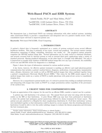
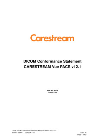
D. Fadda et al.: Transient effects in Herschel/PACS spectroscopy0.95 1.00 1.05 1.10 1.15processing their data with special scripts designed specifically tocorrect transients. The current paper describes how these corrections are made. In the following we describe in detail the different types of transients.0.050.100.15Signal / TelBkg1.151.101.051.000.000.95A sudden change in the illumination of a detector pixel passingfrom one flux level to another, can induce a major transient inthe signal. This occurs typically at the beginning of each observation just after the completion of the calibration block. Becauseof the difference between the flux from internal calibrators andthe telescope background, a transient is usually visible duringthe entire observation.Another common form of this kind of transients is when achange of band, or change of wavelength occurs while observinga source. For example, the user may have requested two different lines occurring at different wavelengths. When the grating iscommanded to access a different part of the spectrum, or changeto a completely different region of the spectrum, a jump in thesignal usually occurs because of the changing emission spectrum of the telescope background at different wavelengths (seeSect. 5.2). If the source is very bright, differences in continuumlevel from the source can also induce a transient.If the source continuum is negligible with respect to the telescope background, it is possible to normalize the signal duringthe whole observation to the telescope background which hasbeen previously calibrated. The transient due to the jump in continuum between the calibration block and the target observationappears clearly, see Fig. 3. It is possible, in this case, to fit thebehaviour with a model and subtract it from the observation. It isinteresting to note that, without this correction, an OFF observation can have a measured flux greater than an ON observation ifit happens to be performed during a period of response stabilization. This effect is not taken into account by the SPG pipeline,so that many observations in the archive have an artificial andconfusing negative background.Some observations that used the unchopped mode containedrequests for more than one band in a single AOR. For extendedsources, a typical raster observation allows one to cover an extended region by moving the telescope to cover a grid of positions. However, for efficiency reasons, the AOR was designedto cycle through all the requested bands at each raster position,before moving the telescope to the next position in the rastersequence. An unexpected side effect of this strategy was thegeneration of transients at each band change. It is not possibleto remove these jump-transients in a clean way in case of suchmultiple-band observations.There is an important lesson to be learned from this experience with PACS. In retrospect, it would have been better toobserve the complete raster in a single band, before cycling tothe next band. This would have minimized the effects of bandinduced jump-transient. We advise that any future mission wheretransient could be an issue, should avoid as much as possiblesudden changes in flux during the observation. This is probablythe case of FIFI-LS onboard SOFIA, which is essentially a cloneof the PACS spectrograph. Unfortunately, when the observational mode was introduced for Herschel, the reduction pipelinewas not fully developed, and it was very difficult to evaluate allthe effects. Since the response was known to stabilize relativelyfast, it was assumed that the effect of a band change was minimal, compared with the advantage of being more time efficient.Experience later showed that jump-transient transient caused byband changes appear to limit the quality of the observation, even1.204.1. Continuum-jump transientsTime [hour]0.00.30.60.91.21.51.8Fig. 3. When the signals from a spaxel are normalized to the expected telescope background a long-term transient after the calibration block becomes clear. In this example (an observation of M81,ObsID 1342269535) an OFF position is observed at the beginning andat the end of the observation (blue dots), while a 2 2 raster observationis performed in the middle (green dots). Since the continuum emissionof the object is negligible with respect to the telescope background, itis possible to fit the general long-term transient (red line) and correctthe signal. Note that many huge transients appear in individual spectralpixels because of cosmic ray hits on the detectors. If this correction isnot made, and an average background is subtracted from the signal, thefinal image will present an artificial gradient and the flux will be negative in some regions. Top inset panel: a close-up of the initial part of thesignal just after the calibration block, showing the strong transient. Theperiodic variation in the signal is a left-over from the imperfect telescope background estimate used for normalization. The empty spacesbetween points occur during telescope slewing.with the most advanced data reduction. Indeed, we are able to seejump-transients even in the blue channel, which has the fastestresponse stabilization compared with the red (see Fig. 4).4.2. Cosmic ray transientsIt is well known that for Ge:Ga detectors, energetic cosmic raysusually produce glitches in the signal, followed by response variations. Depending on the energy of the cosmic ray, the glitchcan be followed by a tail or the variation can be more complicated (lowering temporarily the response). A similar behaviorwas noted in the past for pixels in the ISOCAM array on the Infrared Space Observatory (see, for example, Lari et al. 2001).We will show that the response variation can be described witha combination of exponential functions (see Sect. 5). The mainchallenge to correcting and masking the damage in the signalfrom cosmic ray hits is to select the most significant events, andthen find the starting time which marks the beginning of the discontinuity in the signal.A90, page 5 of 14
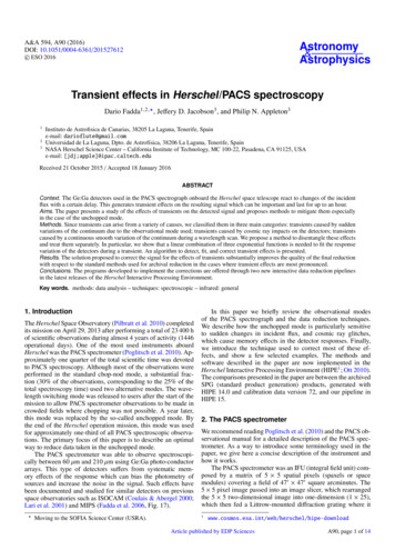
A&A 594, A90 (2016)Signal / TelBkgCR transientsto this first guess spectrum. In this way, each individual detector pixel response to can be studied for the effects of cosmicray transients, and these CR transients can be either corrected ormasked. In the following, we describe the model used to fit theresponse as a function of time and the algorithms applied to thesignal to mitigate the effect of the transients.5.1. ModelDriftThe response variations can be described in general using a combination of exponential functions. We found that a combinationof three exponential functions closely describe the several different cases of transients observed.f (t) a ashort e t/τshort amedium e t/τmedium along e t/τlong .Time [hours]Fig. 4. Long-term transient for the pixels of module 16 in the blue channel of the obsid 1342246963. One of the pixels shows also a transientdue to a cosmic ray hit. There is a 30% variation between the two endsof the observation. Blue and green dots refer to off-target and on-targetparts of the observation, respectively.4.3. Scan dependent transientsFinally, in the case of observations spanning an extended wavelength range, rapid variation of the continuum during the wavelength scan produced transients in the signal (see Sect. 5.4 foran example). In some observations, this last effect is responsiblefor different apparent fluxes in the source spectrum for upwardand downward scans over the same wavelength range. Luckily,many PACS observations using the unchopped mode targetedonly one line with a short range scan. For these cases, scandependent transients had negligible effects. It was found to beimportant only for observations which scanned over extendedwavelength ranges. As a result, two different interactive pipelinescripts (accessible within HIPE as so-called ipipe scripts) havebeen written to treat the unchopped line and unchopped rangecases separately.5. Detecting and modeling transientsTo detect, model, and correct transients in the signal, one has todecouple the signal and the effect of the transients. The best wayto proceed is to obtain an estimate of the response by normalizing the signal to the expected spectrum. As we will s
Herschel was the PACS spectrometer (Poglitsch et al.2010). Ap-proximately one quarter of the total scientific time was devoted to PACS spectroscopy. Although most of the observations were performed in the standard chop-nod mode, a substantial frac-tion (30% of the observations, corresponding to the 25% of the