Transcription
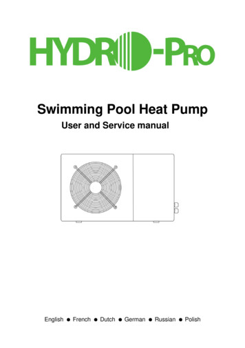
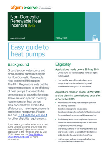
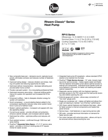
AirHeat PumpsRP15 SeriesRheem Classic SeriesHeat PumpRP15 SeriesEfficiencies: 14-15 SEER/11.5-12.5 EERNominal Sizes 11/2 to 5 Ton [5.28 to 17.6 kW]Cooling Capacities 17.3 to 60.5 kBTU[5.7 to 17.7 kW]“Proper sizing and installation of equipment is critical to achieveoptimal performance. Ask your Dealer for details or visitwww.energystar.gov.” New composite base pan – dampens sound, captures louverpanels, eliminates corrosion and reduces number of fastenersneeded Improved tubing design – reduces vibration and stress, making unit quieter and reducing opportunity for leaks Optimized defrost characteristics - decrease defrosting andprovide better home comfort Powder coat paint system – for a long lasting professional finish Optimized reversing valve sizing – improves shifting performance for quieter unit operation and increased life of thesystem Enhanced mufflers – help to dissipate vibration energy forquieter unit operation Scroll compressor – a sound abating feature added to thecompressor significantly reduces noise when system transitions in and out of defrost mode Modern cabinet aesthetics – increased curb appeal with visually appealing design Curved louver panels – provide ultimate coil protection,enhance cabinet strength, and increased cabinet rigidity Optimized fan orifice – optimizes airflow and reduces unitsound Rust resistant screws – confirmed through 1500-hour saltspray testing PlusOne Expanded Valve Space – 3"-4"-5" service valvespace – provides a minimum working area of 27-squareinches for easier access Integrated heat pump lift receptacle – allows standard CPVCstands to be inserted into the base PlusOne Triple Service Access – 15" wide, industry leading corner service access – makes repairs easier and faster.The two fastener removable corner allows optimal access tointernal unit components. Individual louver panels come outonce fastener is removed, for faster coil cleaning and easiercabinet reassembly Diagnostic service window with two-fastener opening –provides access to the TXV valves and the heat pump reversing valve before opening the unit. External gauge port access – allows easy connection of“low-loss” gauge ports Single-row condenser coil – makes unit lighter and allows thorough coil cleaning to maintain “out of the box” performance 35% fewer cabinet fasteners and fastener-free base – allowfor faster access to internal components and hassle-freepanel removal Service trays – hold fasteners or caps during service calls QR code – provides technical information on demand forfaster service calls Fan motor harness with extra-long wires – allows unit top tobe removed without disconnecting fan wireFORM NO. P11-807 REV. 1
AirTable of ContentsRP15 SeriesTABLE OF CONTENTSStandard Feature Table .3Available SKUs .3Features & Benefits .4-5Model Number Identification .6-7Physical Data .8Electrical Data .8Accessories .9Weighted Sound Power .9Thermostats.9Unit Dimensions.10Clearances .11Wiring Diagrams .12Application Guidelines .12Refrigerant Line Size Information .13-14Performance Data .15-30Guide Specifications .31Limited Warranty .322
AirStandard Feature Table/Available SKUsRP15 SeriesStandard Feature TableFeatureR-410a RefrigerantMaximum SEERMaximum EERScroll CompressorField Installed Filter DrierFront Seating Service ValvesHigh Pressure SwitchLow Pressure SwitchInternal Pressure Relief ValveInternal Thermal OverloadLong Line capabilityLow Ambient capability with Kit3-4-5 Service Valve AccessComposite Basepan2 Screw Control Box Access15" Access to Internal ComponentsQuick release louver panel designNo fasteners to remove along bottomOptimized Venturi AirflowSingle row condenser coilPowder coated paintRust resistant screwsQR codeExternal gauge portsService trays18243036424860 15.012.5 15.012.5 15.012.5 15.012.5 15.012.5 15.012.5 15.012.5 StandardAvailable SKUAvailable ModelsDescriptionRP1518AJ1NAClassic 1 1/2 ton 15 SEER Single-Stage Heat Pump-208/230/1/60RP1524AJ1NAClassic 2 ton 15 SEER Single-Stage Heat Pump-208/230/1/60RP1530AJ1NAClassic 2 1/2 ton 15 SEER Single-Stage Heat Pump-208/230/1/60RP1536AJ1NAClassic 3 ton 15 SEER Single-Stage Heat Pump-208/230/1/60RP1542AJ1NAClassic 3 1/2 ton 15 SEER Single-Stage Heat Pump-208/230/1/60RP1548AJ1NAClassic 4 ton 15 SEER Single-Stage Heat Pump-208/230/1/60RP1560AJ1NAClassic 5 ton 15 SEER Single-Stage Heat Pump-208/230/1/60RP1536AC1NAClassic 3 ton 15 SEER Single-Stage Heat Pump-208/230/3/60RP1542AC1NAClassic 3 1/2 ton 15 SEER Single-Stage Heat Pump-208/230/3/60RP1548AC1NAClassic 4 ton 15 SEER Single-Stage Heat Pump-208/230/3/60RP1560AC1NAClassic 5 ton 15 SEER Single-Stage Heat Pump-208/230/3/60RP1536AD1NAClassic 3 ton 15 SEER Single-Stage Heat Pump-460/3/60RP1542AD1NAClassic 3 1/2 ton 15 SEER Single-Stage Heat Pump-460/3/60RP1548AD1NAClassic 4 ton 15 SEER Single-Stage Heat Pump-460/3/60RP1560AD1NAClassic 5 ton 15 SEER Single-Stage Heat Pump-460/3/60 3
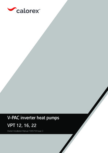
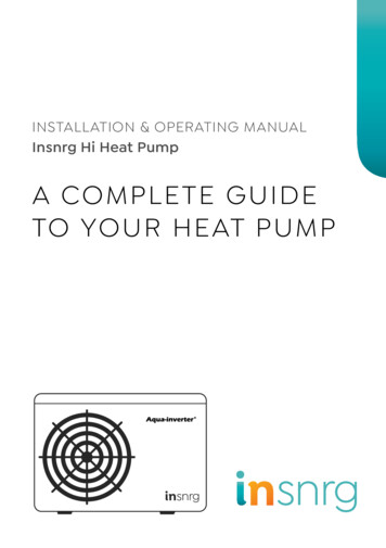
AirFeatures & BenefitsRP15 SeriesIntroduction to RP15 Heat PumpThe RP15 is our 15 SEER heat pump and is part of the Rheemheat pump product line that extends from 14 to 20 SEER. Thishighly featured and reliable heat pump is designed for years ofreliable, efficient operation when matched with Rheem indooraluminum evaporator coils and furnaces or air handler units withaluminum evaporators.Our unique composite base ( 1 ) reduces sound emission, eliminates rattles, significantly reduces fasteners, eliminates corrosionand has integrated brass compressor attachment inserts ( 2 ).Furthermore it has incorporated into the design, water management features, means for hand placement ( 3 ) for unit maneuvering, screw trays ( 4 ) and inserts for lifting unit off pad. ( 5 )1246435Service Valves ( 6 ) are rigidly mounted in the composite basewith 3" between suction and discharge valves, 4" clearancebelow service valves and a minimum of 5" above the servicevalves, creating industry leading installation ease. The minimum27-square inches around the service valves allows ample roomto remove service valve schrader prior to brazing, plenty ofclearance for easy brazing of the suction and discharge lines toservice valve outlets, easy access and hookup of low loss refrigerant gauges ( 7 ), and access to the service valve caps foropening. For applications with long-line lengths up to 250 feettotal equivalent length, up to 200 feet heat pump above evaporator, or up to 80 feet evaporator above heat pump, the long-lineinstructions in the installation manual should be followed.781213If in the rare event, greater access is needed to internal components, such as the compressor, the entire corner of the unit canbe removed along with the top cover assembly to have unprecedented access to interior of the unit ( 14 ). Extra wire length isincorporated into each outdoor fan and compressor so top coverand control panel can be positioned next to unit. With minimaleffort the plug can be removed from the compressor and theoutdoor fan wires can be removed from the capacitor to alloweven more uncluttered access to the interior of the unit ( 15 ).Outdoor coils heights range from as short as 25" to 45", aidingaccess to the compressor. Disassembly to this degree and complete reassembly only takes a first time service technician lessthan 10 minutes. ( 18 )18161514All units utilize strong formed louver panels which provide industry leading coil protection. Louver removal for coil cleaning isaccomplished by removing one screw and lifting the panel outof the composite base pan ( 17 ). All RP15 units utilize single rowcoils ( 16 ) making cleaning easy and complete, restoring theperformance of the heat pump back to out of the box performance levels year after year.1117910Controls are accessed from the corner of the unit by removingonly two fasteners from the control access cover, revealing theindustry’s largest 15" wide and 14" tall control area ( 8 ). With allthis room in the control area the high voltage electrical whip ( 9 )can easily be inserted through the right size opening in the bottom of the control area. Routing it leads directly to contractorlugs for connection. The low voltage control wires ( 10 ) are easilyconnected to units low voltage wiring. If contactor, defrost control or capacitor ( 11 ) needs to be replaced there is more thanadequate space to make the repair. Furthermore, the servicewindow ( 12 ) can be removed to access the TXV and reversingvalve by removing two screws or the entire corner can be removedproviding ultimate access to the TXV or reversing valve. ( 13 )4The outdoor fan motor has sleeve bearings and is inherentlyprotected. The motor is totally enclosed for maximum protectionfrom weather, dust and corrosion. Access to the outdoor fan ismade by removing four fasteners from the fan grille. The outdoorfan can be removed from the fan grille by removing 4 fastenersin the rare case outdoor fan motor fails.Each cabinet has optimized composite ( 19 ) fan orifice assuringefficient and quiet airflow.19
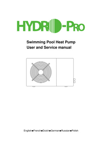
AirThe entire cabinet has powder post paint ( 20 ) achieving 1000hour salt spray rating, allowing the cabinet to retain its aestheticsthroughout its life.2420232221Scroll compressors with standard internal pressure relief andinternal thermal overload are used on all capacities assuringlongevity of high efficient and quiet operation for the life of theproduct. All RP15 Heat Pumps come standard with high and lowpressure switches.Each unit is shipped with filter drier for field installation and willtrap any moisture or dirt that could contaminate the refrigerantsystem.25Features & BenefitsRP15 SeriesAll units have been ship tested to assure units meet stringent“over the road” shipping conditions.As manufactured all units in the RP15 family have cooling capability to 55 F. Addition of low ambient control will allow the unitto operate down to 0 F.Factory testing is performed on each unit. All component partsmeet well defined specification and continually go throughreceiving inspections. Each component installed on a unit isscanned, assuring correct component utilization for a given unitcapacity and voltage. All condenser coils are leak tested withpressurization test to 550#’s and once installed and assembled,each units’ complete refrigerant system is helium leak tested. Allunits are fully charged from the factory for up to 15 feet of piping. All units are factory run tested. The RP15 has a 10-yearconditional compressor and parts warranty (registration required).Optional Accessories (Refer to accessory chart for model #)Compressor Crankcase Heater Protects against refrigerant migration that can occur duringlow ambient operationCompressor Sound Cover Reinforced vinyl compressor cover containing a 1½ inch thickbatt of fiberglass insulation Open edges are sealed with a one-inch wide hook and loopfastening tapeAll cabinets have industry leading structural strength due to thecomposite base pan ( 21 ), interlocking corner post ( 22 ), formedcurved louver panels ( 23 ) and drawn top cover ( 24 ) making itthe most durable cabinet on the market today.Each RP15 capacity has undergone rigorous psychrometrictesting to assure performance ratings of capacity,SEER, EER and HSPF per AHRI Standard 210/240rating conditions. Also each unit bears the UL markand each unit is certified to UL 1995 safety standards.Each unit has undergone specific strain and modal testing toassure tubing ( 25 ) is outside the units natural frequency and thatthe suction and discharge lines connected to the compressorwithstand any starting, steady state operation or shut downforces imposed by the compressor.Compressor hard Start Kit Single-phase units are equipped with a PSC compressormotor. This type of motor normally does not need a potentialrelay and start capacitor In conditions such as low voltage, this kit may be required toincrease the compressor starting torqueLow Ambient Kit Heat Pump operate satisfactorily in the cooling mode down to55 F outdoor air temperature without any additional controls Kit can be added in the field enabling unit to operate properlydown to 0 in the cooling mode Crankcase heater and freezestat should be installed on compressors equipped with a low ambient kit3"/6"/12" Gray high density polyethylene feet are available to raise unitoff of mounting surface away from moistureAll units have been sound tested in sound chamber to AHRI 270rating conditions, and A-weighted Sound Power Level tablesproduced, assuring units have acceptable noise qualities (seepage 9). Each unit has been ran in cooling operation at 95 F and47 F and sound ratings for the RP15 range from as low as 73dBA to 79 dBA.5
6ProductCategoryBrandSEER15ProductCategoryA - Air ConditionersBrand13 - 13 SEER14 - 14 SEER16 - 16 SEER17 - 17 SEER20 - 20 SEERSEER14ProductCategoryC - Evap CoilBrandF - Furn CoilH - Air-Handler CoilTypeF[ ] Designates Metric ConversionsRheemCRFurnace Coils (For Reference)RheemARCapacityBTU/HR24Major Series*ACapacityBTU/HR24 - 24,000 [7.03 kW]36 - 36,000 [10.55 kW]48 - 48,000 [14.07 kW]60 - 60,000 [17.58 kW]24CapacityBTU/HR [kW]18 - 18,000 [5.28 kW]24 - 24,000 [7.03 kW]30 - 30,000 [8.79 kW]36 - 36,000 [10.55 kW]42 - 42,000 [12.31 kW]48 - 48,000 [14.07 kW]60 - 60,000 [17.58 kW]2414 - 14"17 - 17.5"21 - 21"24 - istonTJ - 1ph, 208-230/60C - 3ph, 208-230/60D - 3ph, 460/60VoltageJJ - 1ph, 208-230/60C - 3ph, 208-230/60D - 3ph, 460/60VoltageJS- Standard Eff.M- Mid Eff.H- High Eff.A - 1st DesignMajor Series*A18 - 18,000 [5.28 kW] A - 1st Design24 - 24,000 [7.03 kW]30 - 30,000 [8.79 kW]36 - 36,000 [10.55 kW]42 - 42,000 [12.31 kW]48 - 48,000 [14.07 kW]60 - 60,000 [17.58 kW]Air Conditioners (For Reference)Rheem P - Heat Pump 13 - 13 SEER14 - 14 SEER15 - 15 SEER17 - 17 SEER20 - 20 SEERPRHeat PumpsControlsNMinorSeries**AA -1st DesignMajor Series*A1 - Single-stage2 - Two-stageV - InverterType1M - Multi-poiseOrientationMCA*A - 1st Design*OptionCodeN/AN/AOption Code*N/AOptionCodeMinor Series**AA - 1st DesignMinor Series**C - CasedU - UncasedCasingC - CommunicatingN - Non-communicatingControlsN1 - Single-stage C - CommunicatingA - 1st DesignV - InverterN - Non-communicatingP - PistonType1AirModel Number IdentificationRP15 Series
V - VariablespeedT - ConstantTorque(X-13)P - PSC90 - 90 AFUE92 - 92 AFUE95 - 95 AFUE96 - 96 AFUE97 - 97 AFUERheemA - 1st DesignMajor RevA1 - Single-stage2 - Two-stage80 - 80 AFUERheemH1T36V - Variable speedT - Constant Torque (X-13)P - PSC premiumS - PSC standardMotorV[ ] Designates Metric ConversionsCoil SizeSAir Flow3TA17NConfigurationMAM - MultiD - DownZ - Down &zero clearancedown flowConfigurationMM - Multi-poiseCabinetWidth14 - 14"17 - 17.5"21 - 21"24 - 24.5"17CabinetWidth14 - 14"17 - 17.5"21 - 21"24 - 24.5"3 - up to 3 ton4 - 2 1/2 to 4 ton5 - 3 1/2 up to 5 tonAir Flow33 - up to 3 ton5 - 3 1/2 up to 5 tonInputBTU/HR [kW]050 - 50,000 [15 kW]075 - 75,000 [22 kW]100 - 100,000 [29 kW]125 - 125,000 [37 kW]150 - 150,000 [44 kW]0751 - Single-stage2 - Two-stageM - ModulatingStages2AX - Low NoxS - StandardNoxSX - Low NoxS - StandardNoxS000*A - 1stDesignMinor RevAA - 1st DesignMinor RevAMetering Major Series*ControlsVoltageMinor Factory OptionDeviceSeries** Heat Cap Code14 - 14" S - Standard Efficiency T - TEV A -1st Design C - CommunicatingA - 1ph, 115/60A -1st 00 - noN/A17 - 17.5" M -Mid EfficiencyE - EEVN - Non-communicating J - 1ph, 208-240/60 Design factory21 - 21" H - High EfficiencyP - PistonD - 3ph, 480/60heat with24 - 24.5"optioncodeWidth17A - 1st DesignMajor RevAInputBTU/HR [kW]040 - 42,000 [12.31 kW]060 - 56,000 [16.41 kW]070 - 70,000 [20.51 kW]085 - 84,000 [24.62 kW]100 - 98,000 [28.72 kW]115 - 112,000 [32.82 kW]70ProductStages ofMotor TypeCapacityCategoryAirflowBTU/HRRheem H - Air Handler 1 - Single-stage V - Variable Speed 24 - 24,000 [7.03 kW]2 - Two-stage T - Constant Torque 36 - 36,000 [10.55 kW]M - Modulating P - PSC48 - 48,000 [14.07 kW]60 - 60,000 [17.58 kW]BrandRAir Handlers (For Reference)StagesSeriesBrand280R80% AFUE Gas Furnaces (For Reference)MotorSeriesBrandV96R90% AFUE Gas Furnaces (For Reference)AirModel Number IdentificationRP15 Series7
AirPhysical Data/Electrical DataRP15 SeriesPhysical DataModel No.#Nominal TonnageValve ConnectionsLiquid Line O.D. – in.Suction Line O.D. – in.Refrigerant (R410A) furnished oz.¹Compressor TypeOutdoor CoilNet face area – Outer CoilNet face area – Inner CoilTube diameter – in.Number of rowsFins per inchOutdoor FanDiameter – in.Number of bladesMotor hpCFMRPMwattsShipping weight – lbs.Operating weight – Electrical Data208/230-1-60Line Voltage Data (Volts-Phase-Hz)Maximum overcurrent protection (amps)²20Minimum circuit ampacity³12CompressorRated load amps9Locked rotor amps48Condenser Fan MotorFull load amps0.7Locked rotor amps1.2Line Voltage Data (Volts-Phase-Hz)—Maximum overcurrent protection (amps)²—Minimum circuit ampacity³—CompressorRated load amps—Locked rotor amps—Condenser Fan MotorFull load amps—Locked rotor amps—Line Voltage Data (Volts-Phase-Hz)—Maximum overcurrent protection (amps)²—Minimum circuit ampacity³—CompressorRated load amps—Locked rotor amps—Condenser Fan MotorFull load amps—Locked rotor amps—¹Refrigerant charge sufficient for 15 ft. length of refrigerant lines. For longer line set requirements see the installation instructions for information about set length and additionalrefrigerant charge required.²HACR type circuit breaker of fuse.³Refer to National Electrical Code manual to determine wire, fuse and disconnect size requirements.8
AirAccessories/Weighted Sound Power/ThermostatsRP15 SeriesAccessoriesModel No.Compressor crankcase -45Factory StandardFactory 23427-2668-23427-2568-23427-2568-23427-25Low ambient controlCompressor sound coverCompressor hard start kitLow pressure control*High pressure control*Liquid Line Solenoid(24 VAC, 50/60 Hz)SK-A1SK-A1SK-A1SK-A1SK-A1SK-A1SK-A1Factory StandardFactory StandardFactory StandardFactory StandardFactory StandardFactory StandardFactory StandardFactory StandardFactory StandardFactory StandardFactory StandardFactory StandardFactory StandardFactory StandardSolenoid VLC200RD2T3TVLC200RD3T3TVLC200RD3T3TVLCSolenoid 87KS30387KS30387Solenoid VLC200RD2T3TVLC200RD3T3TVLC200RD3T3TVLCSolenoid 1-101123-2191-101123-2191-101123-21Bi-flow kit*Liquid Line Solenoid(120/240 VAC, 50/60 Hz)Bi-flow kit*Classic Top Cap w/Label*Bi-flow kits are required when installing a liquid line solenoid on a heat pump.Weighted Sound Power Level (dBA)Unit Size – Voltage, SeriesTYPICAL OCTAVE BAND SPECTRUM (dBA without tone adjustment)Standard Rating 35860.558.653.553.751.556.152.155.456.4NOTE: Tested in accordance with AHRI Standard 270-08 (not listed in AHRI)Thermostats200-Series *Programmable300-Series *DeluxeProgrammable500-Series *Communicating/Programmable400-Series *Special Applications/Programmable* Photos are representative. Actual models may vary.For detailed thermostat match-up information,see specification sheet form number T11-001.9
AirUnit DimensionsRP15 SeriesUnit DimensionsOPERATINGMODELNUMBERH (Height)L (Length)SHIPPINGW (Width)H (Height)L (Length)W 8.3897438.38974[ ] Designates Metric Conversions10ST-A1226-02-00
24 (609.6)Service6 (152.4)24 (609.6)24 recommended9 minimum12 (304.8)6 (152.4)24 (609.6)ServiceWALL12 (304.8)24 (609.6)24 recommended9 minimumIMPORTANT: When installing multiple units in an alcove, roof well or partially enclosed area, ensure there is adequate ventillation to prevent re-circulation of discharge air.NOTE: NUMBERS IN () mm18 (457.2)24 (609.6)ServiceWALLCLEARANCESWALL24 (609.6)Service12 (304.8)24 (609.6)ServiceWALLST-A1225-01-006 (152.4)AirClearancesRP15 Series11
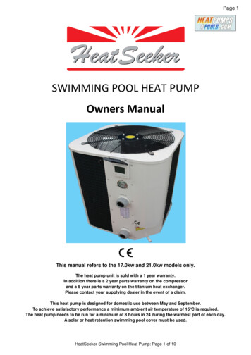
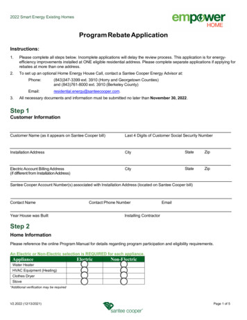
AirWiring Diagram/Application GuidelinesRP15 SeriesControl WiringFIGURE 4CONTROL WIRING FOR AIR HANDLERHeat Pump ThermostatB Y G W2 E C RTYPICAL THERMOSTAT:HEAT PUMP WITHELECTRIC HEATAir HandlerW2W/BLGG/BKYYW1W/BKBBLODDG/YCBRRRHeat PumpOutdoor UnitYBNOTES:1. Jumper “E” to “W2” totransfer control ofsupplemental heat to1st stage when theemergency heat switchis on.2. This wire turns on heatfor defrost, omit for mosteconomical operation.3. Wire with colored tracingstripe.CRDYWIRING INFORMATIONLine Voltage-Field Installed-Factory StandardNOTE: RED WIRE REQUIRED WITH RANCO DDL DEMAND DEFROST CONTROL.Application Guidelines1. Intended for outdoor installation with free air inlet and outlet. Outdoor fan external static pressure available is less than 0.01 -in. wc.2. Minimum outdoor operation air temperature for cooling mode without low-ambient operation accessory is 55 F (12.8 C).3. Maximum outdoor operating air temperature is 125 F (51.7 C).4. For reliable operation, unit should be level in all horizontal planes.5. Use only copper wire for electric connections at unit. Aluminum and clad aluminum are not acceptable for the type of connectorprovided.6. Do not apply capillary tube indoor coils to these units.7. Factory – supplied filter drier must be installed.12
Liquid Line SizeElevation (Above or Below) Indoor CoilTotal Equivalent Length - Feet [m]3/8" [9.53]3/8" [9.53]3/8" [9.53]3/8" [9.53]3/8" [9.53]3/8" [9.53]24303642486020 [6.1]90 [27.43]N/RN/R25 [7.62]25 [7.62] 50 [15.24] 65 [19.81]1/4 [6.35]5/16 [7.94]N/RN/RN/R10 [3.05]25 [7.62] 50 [15.24] 30 [9.14]1/4 [6.35]5/16 [7.94]25 [7.62] 50 [15.24] 55 [16.76]25 [7.62] 50 [15.24] 60 [18.29]7/16 [11.12]1/2 [12.71]60 [18.29]50 [15.24]30 [9.14]N/RN/R25 [7.62] 50 [15.24] 40 [12.19]25 [7.62] 10 [3.05]N/R85 [25.91]80 [24.38]65 [19.81]10 [3.05]N/R3/8 [9.53]5/16 [7.94]N/R25 [7.62] 50 [15.24] 75 [22.86]1/2 [12.71]N/R25 [7.62] 50 [15.24] 75 [22.86]7/16 [11.12]1/4 [6.35]25 [7.62] 50 [15.24] 70 [21.34]3/8 [9.53]N/R90 [27.43]25 [7.62] 50 [15.24] 75 [22.86]1/2 [12.71]85 [25.91]25 [7.62] 50 [15.24] 75 [22.86]7/16 [11.12]75 [22.86]25 [7.62] 50 [15.24] 75 [22.86]30 [9.14]3/8 [9.53]25 [7.62] 50 [15.24] 45 [13.72]N/R25 [7.62]1/4 [6.35]5/16 [7.94]N/R25 [7.62] 50 [15.24] 75 [22.86] 100 [30.48]1/2 [12.71]95 [28.96]25 [7.62] 50 [15.24] 75 [22.86]7/16 [11.12]85 [25.91]25 [7.62] 50 [15.24] 75 [22.86]50 [15.24]3/8 [9.53]N/R95 [28.96]25 [7.62] 50 [15.24] 75 [22.86]1/2 [12.71]90 [27.43]25 [7.62] 50 [15.24] 75 [22.86]7/16 [11.12]85 [25.91]60 [18.29]25 [7.62] 50 [15.24] 75 [22.86]25 [7.62] 50 [15.24] 70 [21.34]5/16 [7.94]N/R3/8 [9.53]25 [7.62] 30 [9.14]1/4 [6.35]N/RN/R60 [18.29]50 [15.24][6.1]N/RN/R85 [25.91]75 [22.86]55 [16.76]45 [13.72]10 [3.05]N/RN/R80 [24.38]75 [22.86]50 [15.24]N/RN/R55 [16.76]N/R90 [27.43]80 [24.38]55 [16.76]50 [15.24]35 [10.67]N/RN/RN/R80 [24.38]70 [21.34]35 [10.67]N/RN/R85 [25.91]75 [22.86]50 [15.24]N/RN/R95 [28.96]85 [25.91]65 [19.81]50 [15.24]30 [9.14]N/RN/RN/R80 [24.38]65 [19.81]30 [9.14]N/RN/R85 [25.91]75 [22.86]45 [13.72]N/RN/R95 [28.96]85 [25.91]65 [19.81]N/RN/R90 [27.43]85 [25.91]N/RN/R40 [12.19][6.1]70 [21.34]20N/R95 [28.96]85 [25.91]45 [13.72]N/R90 [27.43]85 [25.91]70 [21.34]30 [9.14]N/R95 [28.96]85 [25.91]N/RN/R80 [24.38]70 [21.34]40 [12.19]N/RN/R90 [27.43]80 [24.38]55 [16.76]N/R60 [18.29]N/RN/R95 [28.96]90 [27.43]70 [21.34]15 [4.57]N/R90 [27.43]85 [25.91]75 [22.86]35 [10.67]N/R95 [28.96]90 [27.43]N/R95 [28.96]90 [27.43]75 [22.86]25 [7.62]N/R90 [27.43]90 [27.43]80 [24.38]45 [13.72]N/RN/R90 [27.43]85 [25.91]65 [19.81]10 [3.05]N/R95 [28.96]95 [28.96]80 [24.38]40 [12.19]N/R95 [28.96]90 [27.43]80 [24.38]55 [16.76]20N/R90 [27.43]65 [19.81]N/R90 [27.43]60 [18.29][6.1]45 [13.72]25 [7.62]N/RN/RN/R75 [22.86]60 [18.29]15 [4.57]N/RN/R85 [25.91]70 [21.34]30 [9.14]N/RN/R90 [27.43]80 [24.38]55 [16.76]N/RN/R90 [27.43]80 [24.38]65 [19.81]N/RN/R95 [28.96]95 [28.96]80 [24.38]N/R[6.1]N/R45 [13.72]20N/RN/R75 [22.86]55 [16.76]10 [3.05]N/RN/R80 [24.38]65 [19.81]25 [7.62]N/RN/R90 [27.43]80 [24.38]50 [15.24]N/RN/R90 [27.43]80 [24.38]60 [18.29]N/RN/R95 [28.96]90 [27.43]75 [22.86]25 [7.62][ ] Designates Metric Conversions50 [15.24]25 [7.62]N/RN/RN/R75 [22.86]60 [18.29]20N/RN/R85 [25.91]70 [21.34]40 [12.19]N/RN/R95 [28.96]85 [25.91]60 [18.29]N/RN/R90 [27.43]85 [25.91]65 [19.81]10 [3.05]N/R95 [28.96]80 [24.38]35 [10.67]N/R[32] 100 [30.48] 100 [30.48]N/R40 [12.19][32] 105N/R25 [7.62] 50 [15.24] 75 [22.86] 100 [30.48] 100 [30.48] 100 [30.48] 100 [30.48] 100 [30.48] 100 [30.48] 100 [30.48]95 [28.96]90 [27.43]60 [18.29][32] 105N/R50 [15.24][32] 105N/R1/2 [12.71]90 [27.43]70 [21.34][32] 105N/R65 [19.81][32] 105N/R25 [7.62] 50 [15.24] 75 [22.86] 100 [30.48] 100 [30.48]95 [28.96]95 [28.96]N/R70 [21.34]25 [7.62] 50 [15.24] 75 [22.86]80 [24.38]95 [28.96]N/R70 [21.34]3/8 [9.53]25 [7.62] 50 [15.24] 75 [22.86]5/16 [7.94]N/R95 [28.96]N/R75 [22.86]7/16 [11.12]25 [7.62] 50 [15.24] 30 [9.14]1/4 [6.35]25 [7.62] 50 [15.24] 75 [22.86] 100 [30.48] 105N/R80 [24.38][32] 100 [30.48] 100 [30.48] 100 [30.48] 100 [30.48] 100 [30.48] 100 [30.48] 100 [30.48]25 [7.62] 50 [15.24] 75 [22.86] 100 [30.48] 1051/2 [12.71]85 [25.91]7/16 [11.12]85 [25.91]25 [7.62] 50 [15.24] 75 [22.86] 100 [30.48] 100 [30.48] 100 [30.48]90 [27.43]Maximum Vertical Separation – Feet [m]35 [10.67]3/8 [9.53]25 [7.62] 50 [15.24] 75 [22.86]5/16 [7.94]50 [15.24]NOTES:N/R Application not recommended.Grey This application is acceptable, but the long line guidelines must be followed. Reference Long Line Set section in the I&O3/8" [9.53]25 [7.62] 50 [15.24] 60 [18.29]1/4 [6.35]Liquid Line SizeLiquid Line SizeConnection Size(Inch O.D.) [mm](Inch I.D.) [mm]25 [7.62] 50 [15.24] 75 [22.86] 100 [30.48] 125 [45.72] 150 [45.72] 175 [53.34] 200 [60.96] 225 [68.58] 250 [76.20] 275 [83.82] 300 [91.44]18R-410A SystemCapacity ModelHeat Pump Refrigerant Line Size InformationAirRefrigerant Line Size InformationRP15 Series13
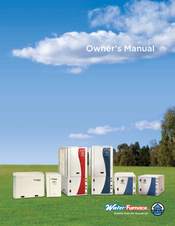
143/4" [19.06]3/4" [19.06]3/4" [19.06]3/4" [19.06]3/4" [19.06]3/4" [19.06]243036424860NOTES:N/R Application not recommended.All calculations assume a 3/8" liquid line3/4" [19.06]18R-410A SystemCapacity N/R1.001.001.00N/RN/R0.993/4 [19.05]7/8 [22.23]1 [25.4]1-1/8 [28.58]5/8 [15.88]3/4 [19.05]1 [25.4]1-1/8 [28.58]5/8 [15.88]3/4 0N/R1 [25.4]1-1/8 [28.58]5/8 [15.88]3/4 [19.05]7/8 [22.23]1 [25.4]1-1/8 [28.58]5/8 [15.88]3/4 [19.05]7/8 [22.23]1 [25.4]1-1/8 [28.58]3/4 [19.05]1.000
Efficiencies: 14-15 SEER/11.5-12.5 EER Nominal Sizes 11/2 to 5 Ton [5.28 to 17.6 kW] Cooling Capacities 17.3 to 60.5 kBTU [5.7 to 17.7 kW] . heat pump product line that extends from 14 to 20 SEER. This highly featured and reliable heat pump is designed for years of