Transcription
HP ProLiant DL380p Gen8 ServerUser GuideAbstractThis document is for the person who installs, administers, and troubleshoots servers and storage systems. HP assumes you are qualified in theservicing of computer equipment and trained in recognizing hazards in products with hazardous energy levels.Part Number: 661848-003November 2012Edition: 3
Copyright 2012 Hewlett-Packard Development Company, L.P.The information contained herein is subject to change without notice. The only warranties for HP products and services are set forth in the expresswarranty statements accompanying such products and services. Nothing herein should be construed as constituting an additional warranty. HP shallnot be liable for technical or editorial errors or omissions contained herein.Microsoft , Windows , and Windows Server are U.S. registered trademarks of Microsoft Corporation.
ContentsComponent identification . 7Front panel components . 7Front panel LEDs and buttons . 9Access the Systems Insight Display. 10Systems Insight Display LEDs . 11Systems Insight Display LED combinations . 12Rear panel components . 13Rear panel LEDs and buttons . 14Non-hot-plug PCI riser board slot definitions. 14System board components . 15System maintenance switch . 16NMI functionality . 17DIMM slot locations . 18SAS and SATA device numbers . 18Drive LED definitions . 19PCI riser cage LED . 20FBWC module LEDs (P222, P420, P421) . 21Hot-plug fans . 21Operations. 23Power up the server . 23Power down the server . 23Extend the server from the rack . 23Remove the access panel. 24Install the access panel. 25Access the product rear panel . 25Opening the cable management arm . 25Remove the hot-plug fan cage . 26Remove the hot-plug fan . 27Remove the full-length expansion board. 28Remove the PCI riser cage . 29Install the PCI riser cage . 30Secure the full-length expansion board retainer . 31Remove the air baffle . 32Setup. 34Optional installation services . 34Rack planning resources. 34Optimum environment . 34Space and airflow requirements . 35Temperature requirements . 35Power requirements . 36Electrical grounding requirements . 36Connecting a DC power cable to a DC power source . 36Rack warnings . 37Identifying the contents of the server shipping carton . 38Installing hardware options . 38Contents3
Installing the server into the rack. 38Installing the operating system. 40Powering on and selecting boot options . 40Registering the server . 41Hardware options installation . 42Introduction . 42Processor and fan option . 42Memory options . 49HP SmartMemory . 50Memory subsystem architecture . 50Single-, dual-, and quad-rank DIMMs . 51DIMM identification . 51Memory configurations. 52General DIMM slot population guidelines . 53Installing a DIMM . 55Hot-plug hard drive options . 55Installing a hot-plug SAS or SATA hard drive . 56Removing a hot-plug SAS or SATA hard drive . 57Controller options . 57Installing the flash-backed write cache module. 58Installing the flash-backed write cache capacitor pack . 59Optical drive option . 63Redundant hot-plug power supply option . 65FlexibleLOM option . 66Expansion board options. 68Removing the expansion slot blanks . 68Installing a half-length expansion board . 69Installing a full-length expansion board . 69Secondary PCI riser cage option . 70Hard drive cage option . 722U rack bezel option . 81HP Trusted Platform Module option . 82Installing the Trusted Platform Module board . 83Retaining the recovery key/password . 84Enabling the Trusted Platform Module. 84Cabling . 86SAS hard drive cabling . 86Optical drive cabling . 87FBWC cabling . 88Chipset SATA cable option . 89150W PCIe power cable option . 92Software and configuration utilities . 94Server mode . 94HP product QuickSpecs. 94HP iLO Management Engine . 94HP iLO . 94Intelligent Provisioning . 96Erase Utility . 97Scripting Toolkit . 97HP Service Pack for ProLiant . 98HP Smart Update Manager . 98Contents4
HP ROM-Based Setup Utility . 99Using RBSU . 99Auto-configuration process . 99Boot options . 100Configuring AMP modes . 100Re-entering the server serial number and product ID . 100Utilities and features . 101Array Configuration Utility . 101Option ROM Configuration for Arrays . 102ROMPaq utility . 102Automatic Server Recovery . 102USB support . 103Redundant ROM support . 103Keeping the system current . 103Drivers . 103Software and firmware . 104Version control . 104HP operating systems and virtualization software support for ProLiant servers . 104HP Technology Service Portfolio . 105Change control and proactive notification . 105Troubleshooting . 106Troubleshooting resources . 106Battery replacement . 107Regulatory compliance notices . 108Regulatory compliance identification numbers . 108Federal Communications Commission notice . 108FCC rating label . 108FCC Notice, Class A Equipment . 108FCC Notice, Class B Equipment . 108Declaration of conformity for products marked with the FCC logo, United States only . 109Modifications . 109Cables . 109Canadian notice (Avis Canadien) . 109European Union regulatory notice . 110Disposal of waste equipment by users in private households in the European Union . 110Japanese notice . 111BSMI notice . 111Korean notice . 111Chinese notice . 112Laser compliance . 112Battery replacement notice. 112Taiwan battery recycling notice . 113Power cord statement for Japan. 113Electrostatic discharge . 114Preventing electrostatic discharge . 114Grounding methods to prevent electrostatic discharge . 114Specifications . 115Environmental specifications . 115Mechanical specifications . 115Power supply specifications . 115Contents5
HPHPHPHPHPHP460 W CS HE Power Supply (92%) specifications . 116460 W CS Platinum Power Supply (94%) specifications . 116750 W CS HE Power Supply (92%) specifications . 116750 W CS Platinum Power Supply (94%) specifications . 117750 W 48V CS Power Supply specifications . 1171200 W CS HE Power Supply (94%) specifications . 118Support and other resources . 119Before you contact HP. 119HP contact information . 119Customer Self Repair . 119Acronyms and abbreviations . 127Documentation feedback . 130Index . 131Contents6
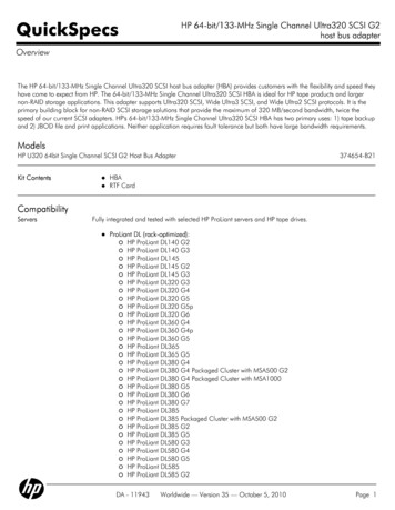
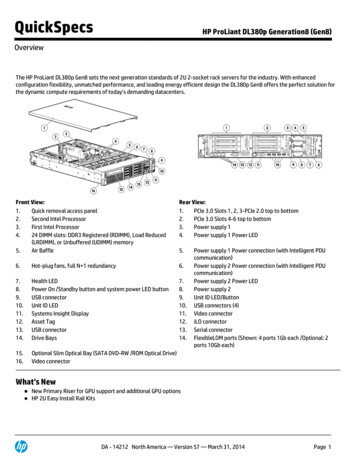
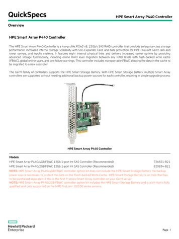
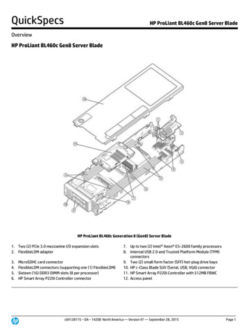
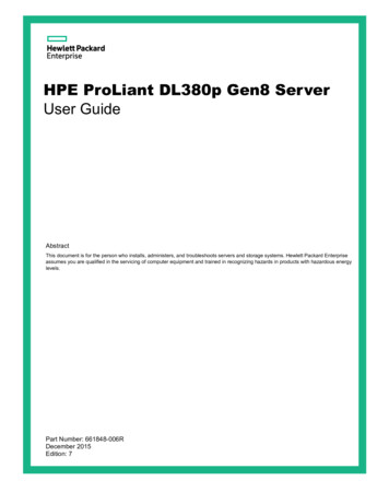
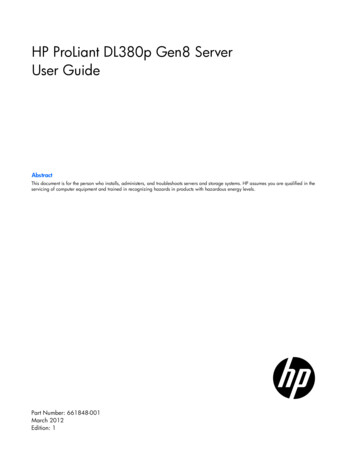
Component identificationFront panel components SFF model (8-drive)ItemDescription1Video connector2SATA optical drive bay3Drive bays4Systems Insight Display5USB connectors (2) SFF model with optional hard drive cage (16-drive)ItemDescription1Video connector2Drive bays (box 1)3Drive bays (box 2)4Systems Insight Display5USB connectors (2)Component identification 7
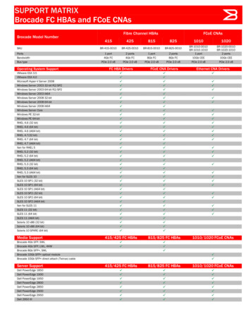
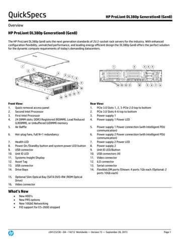
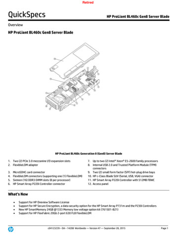
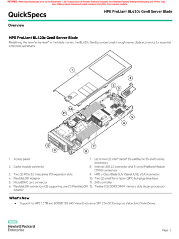
SFF model (25-drive)ItemDescription1Video connector2Quick release levers (2)3Drive bays4USB connector LFF model (8-drive)ItemDescription1Video connector2SATA optical drive bay3Drive bays4Systems Insight Display5USB connectors (2)Component identification 8
LFF model (12-drive)ItemDescription1Video connector2Quick-release levers (2)3Drive bays4USB connectorFront panel LEDs and buttonsItemDescriptionStatus1Power On/Standby buttonand system power LEDSolid green System onFlashing green (1 Hz/cycle per sec) Performing power on sequenceSolid amber System in standbyOff No power present*Component identification 9
ItemDescriptionStatus2Health LEDSolid green NormalFlashing amber System degradedFlashing red (1 Hz/cycle per sec) System criticalFast-flashing red (4 Hz/cycles per sec) Power fault**3NIC status LEDSolid green Link to networkFlashing green (1 Hz/cycle per sec) Network activeOff No network activity4UID button/LEDSolid blue ActivatedFlashing blue (1 Hz/cycle per sec) Remote management orfirmware upgrade in progressOff Deactivated*Facility power is not present, power cord is not attached, no power supplies are installed, power supply failure hasoccurred, or the power button cable is disconnected.**To identify components in a degraded or critical state, see the Systems Insight Display LEDs, check iLO/BIOS logs, andreference the server troubleshooting guide.Access the Systems Insight DisplayTo access a pop-out HP Systems Insight Display:1.Press and release the panel.2.After the display fully ejects, rotate the display downward to view the LEDs.Component identification 10
Systems Insight Display LEDsThe HP Systems Insight Display LEDs represent the system board layout. The display enables diagnosis withthe access panel installed.ItemDescriptionStatus1Power capOff System is in standby, or no cap is set.Solid green Power cap applied2NIC link/activityOff No link to network. If the power is off,view the rear panel RJ-45 LEDs for status("Rear panel LEDs and buttons" on page14).Flashing green Network link and activitySolid green Network link3AMP statusOff AMP modes disabledSolid green AMP mode enabledSolid amber FailoverFlashing amber Invalid configuration4Over tempOff NormalSolid amber High system temperaturedetected—All other LEDsOff NormalAmber FailureFor more information on the activation ofthese LEDs, see "Systems Insight DisplayLED combinations (on page 12)."Component identification 11
Systems Insight Display LED combinationsWhen the health LED on the front panel illuminates either amber or red, the server is experiencing a healthevent. Combinations of illuminated Systems Insight Display LEDs, the system power LED, and the health LEDindicate system status.Systems Insight Display Health LEDLED and colorProcessor (amber)RedSystem powerLEDStatusAmberOne or more of the following conditions mayexist: Processor in socket X has failed.Processor X is not installed in the socket.Processor X is unsupported.ROM detects a failed processor duringPOST.Processor (amber)AmberGreenProcessor in socket X is in a pre-failurecondition.DIMM (amber)RedGreenOne or more DIMMs have failed.DIMM (amber)AmberGreenDIMM in slot X is in a pre-failure condition.Over temp (amber)AmberGreenThe Health Driver has detected a cautionarytemperature level.Over temp (amber)RedAmberThe server has detected a hardware criticaltemperature level.PCI riser (amber)RedGreenThe PCI riser cage is not seated properly.Fan (amber)AmberGreenOne fan has failed or has been removed.Fan (amber)RedGreenTwo or more fans have failed or beenremoved.Power supply (amber)RedAmberOne or more of the following conditions mayexist: Power supply (amber)AmberGreenOnly one power supply is installed andthat power supply is in standby.Power supply faultSystem board faultOne or more of the following conditions mayexist: Redundant power supply is installed andonly one power supply is functional.AC power cord is not plugged intoredundant power supply.Redundant power supply faultPower supply mismatch at POST orpower supply mismatch through hot-plugadditionPower cap (off)—AmberStandbyPower cap (green)—Flashing greenWaiting for powerPower cap (green)—GreenPower is available.Power cap (flashingamber)—AmberPower is not available.Component identification 12
IMPORTANT: If more than one DIMM slot LED is illuminated, further troubleshooting is required.Test each bank of DIMMs by removing all other DIMMs. Isolate the failed DIMM by replacingeach DIMM in a bank with a known working DIMM.Rear panel componentsItemDescription1PCIe slots 1–3 (top to bottom)2PCIe slots 4–6 (top to bottom)3Power supply 1 (PS1)4PS1 power connector5PS2 power connector6Power supply 2 (PS2)7USB connectors (4)8Video connector9iLO connector10Serial connector11FlexibleLOM ports (Shown: 4x1Gb/Optional: 2x10Gb); port 1 on right sideComponent identification 13
Rear panel LEDs and buttonsItemDescriptionStatus1UID LED/buttonOff DeactivatedSolid blue ActivatedFlashing blue System being managed remotely2Power supply 2LEDOff System is off or power supply has failed.Solid green Normal3Power supply 1LEDOff System is off or power supply has failed.Solid green Normal4NIC activity LEDOff No network activitySolid green Link to networkFlashing green Network activity5NIC link LEDOff No network linkGreen Network linkNon-hot-plug PCI riser board slot definitions Primary riser cage connector, connected to processor 1 or the southbridgePCIe 3-slot riser cage*PCIe 2-slot x16 riser cage1 - FL/FHPCIe2 or PCIe3** x16 (16,8,4,2,1)—2 - HL/FHPCIe2 or PCIe3** x8 (8,4,2,1)—3 - HL/FHPCIe2 x8 (4,2,1)†— Secondary riser cage connector, connected to processor 2 (Processor 2 must be installed)PCIe 3-slot riser cage*PCIe 2-slot x16 riser cage4 - FL/FHPCIe2 or PCIe3** x16 (16,8,4,2,1)PCIe2 or PCIe3** x16 (16,8,4,2,1)5 - HL/FHPCIe2 or PCIe3** x8 (8,4,2,1)PCIe2 or PCIe3** x16 (16,8,4,2,1)6 - HL/FHPCIe2 or PCIe3** x8 (8,4,2,1)—Compon
HP ProLiant DL380p Gen8 Server User Guide Abstract This document is for the person who installs, administers, and troubleshoots servers and storage systems. HP assumes you are qualified in the servicing of computer equipment and trained in recognizing hazards in products with hazardous energy levels.