Transcription
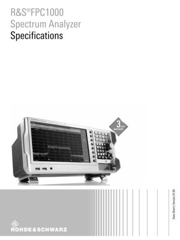
Technical Data SheetSpectrum Master Compact Handheld Spectrum AnalyzerMS2711E9 kHz to 3 GHz
MS2711ESpecificationsIntroductionAnritsu introduces its next generation compact handheld Spectrum Analyzers to meet the needs for portability. Whether itis for spectrum monitoring, broadcast proofing, interference analysis, RF and microwave measurements, or Wi-Fi andwireless network measurements, the Spectrum Master is the ideal instrument for making fast and reliable measurements.Spectrum Analyzer Highlights Measurements: Occupied Bandwidth, Channel Power, ACPR, C/I Traces: Normal, Max Hold, Min Hold, Average, # of Averages Interference Analyzer: Spectrogram, Signal Strength, RSSI, Signal Detectors: Peak, Negative, Sample, Quasi-peak, and true RMSID, Interference Mapping Markers: 6, each with a Delta Marker, or 1 Reference with 6 Dynamic Range: 85 dB in 100 Hz RBWDeltas DANL: –142 dBm in 100 Hz RBW with Preamp Option Phase Noise: –90 dBc/Hz max @ 10 kHz offset at 1 GHz Limit Lines: up to 41 segments with one-button envelopecreation Frequency Accuracy: 1.5 ppm, 50 ppb with GPS Option 31 Trace Save-on-Event: crossing limit line or sweep complete PIM HuntingCapabilities and Functional Highlights Store 2000 Traces internally 4, 6, 8, 18, 26 GHz Power Sensors USB Data Transfer Internal Preamplifier Optional Channel Scanner Optional Master Software Tools Internal Power Meter Optional 5 minute warm-up time 3 hour battery operation time High Accuracy Power Meter Optional Touchscreen keyboard Tracking Generator Optional EMF Test Optional2 of 19PN: 11410-00597 Rev. YMS2711E TDS
SpecificationsMS2711ETable of ContentsDefinitions. . . . . . . . . . . . . . . . . . . . . . . . . . . . . . . . . . . . . . . . . . . . . . . . . . . . . . . . . . . . . . . . . . . . . . . . . . . . . . . . . . . . . 3Spectrum Analyzer . . . . . . . . . . . . . . . . . . . . . . . . . . . . . . . . . . . . . . . . . . . . . . . . . . . . . . . . . . . . . . . . . . . . . . . . . . . . . 4Interference Analyzer (Option 25). . . . . . . . . . . . . . . . . . . . . . . . . . . . . . . . . . . . . . . . . . . . . . . . . . . . . . . . . . . . . . . . . 6Channel Scanner (Option 27) . . . . . . . . . . . . . . . . . . . . . . . . . . . . . . . . . . . . . . . . . . . . . . . . . . . . . . . . . . . . . . . . . . . . . 6Preamplifier (Option 8) . . . . . . . . . . . . . . . . . . . . . . . . . . . . . . . . . . . . . . . . . . . . . . . . . . . . . . . . . . . . . . . . . . . . . . . . . . 6Tracking Generator (Option 20) . . . . . . . . . . . . . . . . . . . . . . . . . . . . . . . . . . . . . . . . . . . . . . . . . . . . . . . . . . . . . . . . . . 6Power Meter (Option 29) . . . . . . . . . . . . . . . . . . . . . . . . . . . . . . . . . . . . . . . . . . . . . . . . . . . . . . . . . . . . . . . . . . . . . . . . 7High Accuracy Power Meter (Option 19) . . . . . . . . . . . . . . . . . . . . . . . . . . . . . . . . . . . . . . . . . . . . . . . . . . . . . . . . . . . 7GPS Receiver (Option 31) . . . . . . . . . . . . . . . . . . . . . . . . . . . . . . . . . . . . . . . . . . . . . . . . . . . . . . . . . . . . . . . . . . . . . . . . 7Electromagnetic Field Test (Option 444) . . . . . . . . . . . . . . . . . . . . . . . . . . . . . . . . . . . . . . . . . . . . . . . . . . . . . . . . . . . 8AM/FM/PM Signal Analyzers (Option 509) . . . . . . . . . . . . . . . . . . . . . . . . . . . . . . . . . . . . . . . . . . . . . . . . . . . . . . . . . . 9General Specifications . . . . . . . . . . . . . . . . . . . . . . . . . . . . . . . . . . . . . . . . . . . . . . . . . . . . . . . . . . . . . . . . . . . . . . . . . 10Line Sweep Tools . . . . . . . . . . . . . . . . . . . . . . . . . . . . . . . . . . . . . . . . . . . . . . . . . . . . . . . . . . . . . . . . . . . . . . . . . . . . . . 11easyTest Tools . . . . . . . . . . . . . . . . . . . . . . . . . . . . . . . . . . . . . . . . . . . . . . . . . . . . . . . . . . . . . . . . . . . . . . . . . . . . . . . . 11Master Software Tools . . . . . . . . . . . . . . . . . . . . . . . . . . . . . . . . . . . . . . . . . . . . . . . . . . . . . . . . . . . . . . . . . . . . . . . . . 11Ordering Information – Options . . . . . . . . . . . . . . . . . . . . . . . . . . . . . . . . . . . . . . . . . . . . . . . . . . . . . . . . . . . . . . . . . 12Standard Accessories . . . . . . . . . . . . . . . . . . . . . . . . . . . . . . . . . . . . . . . . . . . . . . . . . . . . . . . . . . . . . . . . . . . . . . . . . . 12Manuals. . . . . . . . . . . . . . . . . . . . . . . . . . . . . . . . . . . . . . . . . . . . . . . . . . . . . . . . . . . . . . . . . . . . . . . . . . . . . . . . . . . . . . 12Troubleshooting Guides . . . . . . . . . . . . . . . . . . . . . . . . . . . . . . . . . . . . . . . . . . . . . . . . . . . . . . . . . . . . . . . . . . . . . . . . 13Power Sensors . . . . . . . . . . . . . . . . . . . . . . . . . . . . . . . . . . . . . . . . . . . . . . . . . . . . . . . . . . . . . . . . . . . . . . . . . . . . . . . . 13Optional Accessories . . . . . . . . . . . . . . . . . . . . . . . . . . . . . . . . . . . . . . . . . . . . . . . . . . . . . . . . . . . . . . . . . . . . . . . . . . . 13DefinitionsSpecificationsWarm-Up TimeTemperature RangeReference SignalTypical PerformanceUncertaintyCalibration CycleMS2711E TDSAll specifications and characteristics apply under the following conditions, unless otherwise stated:After 10 minutes of warm-up time, where the instrument is left in the ON state.Over the 23 C 5 C temperature range.When using internal reference signal.Typical specifications that are not in parenthesis are not tested and not warranted. They are generallyrepresentative of characteristic performance.Typical specifications in parenthesis () represent the mean value of measured units and do not include anyguard-bands or uncertainties. They are not warranted.A coverage factor of x1 is applied to the measurement uncertainties to facilitate comparison with otherindustry handheld analyzers.Calibration is within the recommended 12 month period (residual specifications also require calibration kitcalibration cycle adherence.)All specifications subject to change without notice. For the most current data sheet, please visit the Anritsuweb site: www.anritsu.comPN: 11410-00597 Rev. Y3 of 19
MS2711ESpecificationsSpectrum AnalyzerSmart MeasurementsField Strength (Uses antenna calibration tables to measure dBm/m2, dBmV/m, dBV/m, dBμV/m, Volt/m,Watt/m2, dBW/m2, A/m, dBA/m and Watt/cm2 )Occupied Bandwidth (Measures 99 % to 1 % power channel of a signal)Channel Power (Measures the total power in a specified bandwidth)ACPR (Adjacent Channel Power Ratio)AM/FM/SSB Demodulation (Wide/narrow FM, USB, and LSB (audio out only))C/I (Carrier-to-interference Ratio)Emission MaskPIM HuntingSetup ave-on-EventRecallCopyDeleteApplication OptionsCenter/Start/Stop, Span, Frequency Step, Signal Standard, Channel #, Channel IncrementReference Level (RL), Scale, Attenuation Auto/Level, RL Offset, Pre-Amp On/Off, DetectionSpan, Span Up/Down (1-2-5), Full Span, Zero Span, Last SpanRBW, Auto RBW, VBW, Auto VBW, RBW/VBW, Span/RBWSave, Save-on-Event, Recall, Copy, DeleteSetups, Measurements, Screen Shots (JPEG), Limit Lines, Spurious Emission MaskCrossing Limit Line, Sweep Complete, Save-then-Stop, Clear AllSetups, Measurements, Limit Lines, Spurious Emission MaskSelected file or files to internal/external memory (USB)Selected file or files from internal/external memory (USB)Impedance (50 Ω, 75 Ω, Other)Sweep FunctionsSweepDetectionTriggersSingle/Continuous, Sweep Mode (Fast, Performance, No FFT), Reset, Detection, Minimum Sweep Time,Trigger TypePeak, RMS, Negative, Sample, Quasi-peakFree Run, External, Video, Change Position, ManualTrace FunctionsTracesTrace A OperationsTrace B OperationsTrace C OperationsUp to three Traces (A, B, C), View/Blank, Write/Hold, Trace A/B/C OperationsNormal, Max Hold, Min Hold, Average, # of Averages, (always the live trace)A B, B C, Max Hold, Min HoldA C, B C, Max Hold, Min Hold, A – B C, B – A C, Relative Reference (dB), ScaleMarker FunctionsMarkersMarker TypesMarker Auto-PositionMarker TableMarkers 1-6 each with a Delta Marker, or Marker 1 Reference with Six Delta Markers, Marker Table (On/Off),All Markers OffStyle (Fixed/Tracking), Noise Marker, Frequency Counter MarkerPeak Search, Next Peak (Right/Left), Peak Threshold %, Set Marker to Channel, Marker Frequency to Center,Delta Marker to Span, Marker to Reference Level1-6 markers frequency and amplitude plus delta markers frequency amplitude and offsetLimit Line FunctionsLimit LinesLimit Line EditLimit Line MoveLimit Line EnvelopeLimit Line AdvancedUpper/Lower, On/Off, Edit, Move, Envelope, Advanced, Limit Alarm, Default LimitFrequency, Amplitude, Add Point, Add Vertical, Delete Point, Next Point Left/RightTo Current Center Frequency, By dB or Hz, To Marker 1, Offset from Marker 1Create Envelope, Update Amplitude, Points (41 max), Offset, Shape Square/SlopeType (Absolute/Relative), Mirror, Save/RecallFrequencyFrequency RangeTuning ResolutionFrequency ReferenceFrequency SpanSweep TimeSweep Time Accuracy9 kHz to 3 GHz (tunable to 0 Hz)1 HzAging: 1.0 ppm/yearAccuracy: 1.5 ppm (25 C 25 C) aging, 50 ppb with GPS On10 Hz to 3 GHz including zero spanMinimum 100 ms, 7 µs to 3600 s in zero span 2 % in zero spanBandwidthResolution Bandwidth (RBW)Video Bandwidth (VBW)RBW with Quasi-Peak DetectionVBW with Quasi-Peak Detection4 of 19100 Hz to 3 MHz in 1–3 sequence 10% (1 MHz max in zero-span) (–3 dB bandwidth)10 Hz to 3 MHz in 1–3 sequence (–3 dB bandwidth) (auto or manually selectable)200 Hz, 9 kHz, 120 kHz (–6 dB bandwidth)Auto VBW is On, RBW/VBW 1PN: 11410-00597 Rev. YMS2711E TDS
SpecificationsMS2711ESpectrum Analyzer (Continued)Spectral PuritySSB Phase Noise @ 1 GHz–90 dBc/Hz, –100 dBc/Hz typical @ 10 kHz offset–95 dBc/Hz, –102 dBc/Hz typical @ 100 kHz offset–105 dBc/Hz, –111 dBc/Hz typical @ 1 MHz offsetAmplitude RangesDynamic RangeMeasurement RangeDisplay RangeReference Level RangeAttenuator RangeMaximum Continuous InputAmplitude Units 85 dB (2.4 GHz), 2/3 (TOI-DANL) in 100 Hz RBWDANL to 26 dBm ( 50 MHz)DANL to 0 dBm ( 50 MHz)1 dB to 15 dB/div in 1 dB steps, ten divisions displayed–150 dBm to 30 dBm0 dB to 55 dB in 5 dB steps 30 dBmLog Scale Modes: dBW, dBm, dBμW, dBV, dBmV, dBμV, dBA, dBmA, dBμALinear Scale Modes: nV, μV, mV, V, kV, nW, μW, mW, W, kW, nA, μA, mA, AAmplitude Accuracy9 kHz to 100 kHz100 kHz to 3.0 GHz 2.0 dB typical (Preamp Off) 1.25 dB, 0.5 dB typicalDisplayed Average Noise Level (DANL)(RBW Normalized to 1 Hz, 0 dB attenuation)10 MHz to 2.4 GHz 2.4 GHz to 3 GHz(RBW 100 Hz, 0 dB attenuation)10 MHz to 2.4 GHz 2.4 GHz to 3 GHzPreamp Off(Reference Level –20 dBm)MaximumTypical–141 dBm–146 dBm–137 dBm–141 dBmPreamp On(Reference Level –50 dBm)MaximumTypical–157 dBm–162 dBm–154 dBm–159 dBm–121 dBm–117 dBm–137 dBm–134 dBm–126 dBm–121 dBm–142 dBm–139 dBmSpursResidual SpuriousInput-Related SpuriousExceptions, typicalThird-Order Intercept (TOI)800 MHz2400 MHz200-2200 MHz 2.2 GHz to 3.0 GHzSecond Harmonic Distortion50 MHz 50 MHz to 200 MHz 200 MHz to 3000 MHzVSWRMS2711E TDS –90 dBm (RF input terminated, 0 dB input attenuation, 10 MHz) –75 dBc (0 dB attenuation, –30 dBm input, span 1.7 GHz, carrier offset 4.5 MHz) –70 dBc @ 2.5 GHz, with 2072.5 MHz Input –68 dBc @ F1 – 280 MHz with F1 Input –70 dBc @ F1 190.5 MHz with F1 Input –52 dBc @ 7349 – (2F2) MHz, with F2 Input, where F2 2437.5 MHz –55 dBc @ 190.5 (F1/2) MHz, F1 1 GHzPreamp Off (–20 dBm tones 100 kHz apart, 10 dB attenuation) 16 dBm 20 dBm 25 dBm, typical 28 dBm, typicalPreamp Off, 0 dB input attenuation, –30 dBm input–56 dBc–60 dBc, typical–70 dBc, typical2:1, typicalPN: 11410-00597 Rev. Y5 of 19
MS2711ESpecificationsInterference Analyzer (Option 25)MeasurementsSpectrumSpectrogramSignal StrengthReceived Signal Strength Indicator (RSSI)Signal IDSignal-to-Noise Ratio (SNR)Interference MappingField StrengthOccupied BandwidthChannel PowerAdjacent Channel Power Ratio (ACPR)AM/FM/SSB Demodulation (Wide/Narrow FM, Upper/Lower SSB), (audio out only)Carrier-to-Interference ratio (C/I)Collect data up 72 hoursGives visual and aural indication of signal strengthCollect data up to 168 hours (one week)Up to 12 signalsCenter Frequency BandwidthSignal Type (FM, GSM, W-CDMA, CDMA, Wi-Fi)Closest Channel NumberNumber of Carriers 10 dBTriangulate location of interference with on-display mapsChannel Scanner (Option 27)GeneralNumber of ChannelsMeasurementsScannerAmplitudeCustom ScanFrequency RangeFrequency AccuracyMeasurement RangeApplication Options1 to 20 ChannelsGraph/Table, Max Hold (On/5 s/Off), Freq/Channel, Current/Max, Single/Dual ColorScan Channels, Scan Frequencies, Scan Customer List, Scan Script Master Reference Level, ScaleSignal Standard, Channel, # of Channels, Channel Step Size, Custom Scan100 kHz to 3 GHz 10 Hz Time base error–110 dBm to 26 dBmImpedance (50 Ω, 75 Ω, Other)Preamplifier (Option 8)GeneralModeGainFrequency RangeSpectrum Analyzer, Interference Analyzer, Channel Scanner17 dB (Typical)100 kHz to 3 GHzTracking Generator (Option 20)Setup ParametersMeasure Set-upInsertion Loss Set-upFrequency RangeOutput Power RangeStep SizeOutput FlatnessZero Span BehaviorOutput ConnectorDamage Level6 of 19Off/On, Output Power, Reset Sweep, Insertion Loss, Abs Max, Min, Avg (On/Off)Normalize (Off/On), Rel Reference, Rel Scale, Transmission, Min, Avg (Off, On) RL Offset500 kHz to 3.0 GHz–50 dBm to 0 dBm0.1 dB nominal 1.0 dB max, 0.3 dB typical(Using field calibration, relative to spectrum analyzer input with 3 dB attenuator)CW OutputType N female, 50 Ω 23 dBm 50 VDC (limited dv/dt)PN: 11410-00597 Rev. YMS2711E TDS
SpecificationsMS2711EPower Meter (Option 29)GeneralFrequencyAmplitudeAverageLimitsFrequency RangeSpanDisplay RangeMeasurement RangeOffset RangeVSWRMaximum PowerAccuracyApplication OptionsCenter/Start/Stop, Span, Frequency Step, Signal Standard, Channel #, Full BandMaximum, Minimum, Offset, Relative On/Off, Units, Auto ScaleAcquisition Fast/Med/Slow, # of Running AveragesLimit On/Off, Limit Upper/Lower10 MHz to 3 GHz1 kHz to 100 MHz–140 dBm to 30 dBm, 40 dB span–120 dBm to 26 dBm0 dB to 100 dB (External Gain or Loss)2:1 typical 30 dBm without attenuatorSame as Spectrum AnalyzerImpedance (50 Ω, 75 Ω, Other)High Accuracy Power Meter (Option 19) (requires external USB Power Sensor)AmplitudeAverageZero/CalLimitsPower Sensor ModelMaximum, Minimum, Offset, Relative On/Off, Units, Auto Scale# of Running Averages, Max HoldZero On/Off, Cal Factor (Center Frequency, Signal Standard)Limit On/Off, Limit Upper/LowerMA24105AMA24106AMA24108A/18A/26A MA24208A/18AMA24330A/40A/50AInline HighPower SensorHigh AccuracyRF Power SensorMicrowave USBPower SensorMicrowaveUniversal USBPower SensorMicrowave CW USBPower Sensor350 MHz to 4 GHz50 MHz to 6 GHz10 MHz to8/18/26 GHz10 MHz to 8/18 GHz 10 MHz to33/40/50 GHzType N(f), 50 ΩType N(m), 50 ΩType N(m), 50 Ω(8/18 GHz)Type K(m), 50 Ω(26 GHz)Type N(m), 50 Ω 3 dBm to 51.76 dBm(2 mW to 150 W)–40 dBm to–40 dBm to–60 dBm to 23 dBm 20 dBm 20 dBm(0.1 µW to 200 mW) (0.1 µW to 100 mW) (1 nW to 100 mW)–70 dBm to 20 dBm(0.1 nW to 100 mW)MeasurandTrue-RMSTrue-RMSTrue-RMS, SlotPower, BurstAverage PowerTrue-RMS, SlotPower, BurstAverage PowerAverage PowerMeasurement Uncertainty 0.17 dBa 0.16 dBb 0.18 dBc 0.17 dBd 0.17 10-00906DescriptionFrequency RangeConnectorDynamic RangeData sheet(for complete specifications)Notes:GPS Receiver (Option 31)Type K(m), 50 Ω(33/40 GHz)Type V(m), 50 Ω(50 GHz)a. Expanded uncertainty with K 2 for power measurements of a CW signal greater than 20 dBm with a matched load.Measurement results referenced to the input side of the sensor.b. Total RSS measurement uncertainty (0 ºC to 50 ºC) for power measurements of a CW signal greater than –20 dBm with zeromismatch errors.c. Expanded uncertainty with K 2 for power measurements of a CW signal greater than –20 dBm with zero mismatch errors.d. Power uncertainty expressed with two sigma confidence level for CW measurement after zero operation. Includescalibration factor and linearity over temperature uncertainties, but not the effects of mismatch, zero set and drift, or noise.e. Includes linearity over temperature uncertainties, but not the effects of calibration factor, mismatch, zero set and drift, andnoise.(Antenna sold separately)GeneralSetupGPS Time/Location IndicatorHigh Frequency AccuracyConnectorMS2711E TDSOn/Off, Antenna Voltage 3.3/5.0 V, GPS InfoTime, Latitude, Longitude and Altitude on displayTime, Latitude, Longitude and Altitude with trace storageSpectrum Analyzer, Interference Analyzer, CW Signal Analyzers 50 ppb with GPS On, GPS antenna connected, 3 minutes after satellite lock in selected modeSMA, FemalePN: 11410-00597 Rev. Y7 of 19
MS2711ESpecificationsElectromagnetic Field Test (Option ayLimit lines, axis dwell time, measurement time, auto-logging, measurement units, trace displayField strength is measureddBm/m2, dBV/m, dBmV/m, dBuV/m, V/m, W/m2, dBW/m2, A/m, dBA/m, W/cm2Maximum, minimum, and average of all measurements conductedMeasurement status, number of measurements taken, pass/fail indicatorsFrequency RangeSupported Antenna2000-1800-R2000-1792-R2000-1791-REMF Measurement Modes8 of 199 kHz to 300 MHz30 MHz to 3 GHz700 MHz to 3 GHzSpectrum AnalyzerPN: 11410-00597 Rev. YMS2711E TDS
SpecificationsMS2711EAM/FM/PM Signal Analyzers (Option 509)MeasurementsDisplayTypeRF SpectrumAM/FM/PMAudio Spectrum(AM)AudioSpectrum(FM/PM)Audio Waveform Audio cDisplayPower (dBm) vs.FrequencyDepth (%) vs.ModulationFrequencyDeviation(kHz/rad) vs.ModulationFrequencyDepth (%) vs. Time Deviation(kHz/rad) vs. TimeNoneNoneNumericalDisplaysCarrier PowerCarrier FrequencyOccupiedBandwidthAM RateRMS Depth(Pk-Pk)/2 DepthSINAD*THD*Distortion/TotalVrms*FM/PM RateRMS talVrms*AM RateRMS Depth(Pk-Pk)/2 DepthSINAD*THD*Distortion/TotalVrms*RMS Depth (AM)Peak DepthPeak – Depth(Pk-Pk)/2 DepthCarrier PowerCarrier FrequencyOccupiedBandwidthAM RateSINAD*THD*Distortion/TotalVrms*RMS Deviation(FM/PM)Peak DepthPeak – Depth(Pk-Pk)/2 DepthCarrier PowerCarrier FrequencyOccupiedBandwidthAM RateSINAD*THD*Distortion/TotalVrms*FM/PM RateRMS Depth(Pk-Pk)/2 DepthSINAD*THD*Distortion/TotalVrms** Requires Sinewave modulationSetup rCenter Freq, Span, Freq Step, Signal Standard, Channel, Channel Increment, Set Carrier FreqScale, Power Offset, Adjust RangeDemod Type (AM, FM, PM), IFBW, Auto IFBWRF Spectrum AM/FM/PM, Audio Spectrum (AM/FM/PM), Audio Waveform (AM/FM/PM),Summary (AM/FM/PM), AverageOn/Off, Delta, Peak Search, Marker Freq to Center, Marker to Ref Lvl, Marker Table, All Markers OffSpecificationsAMFMPMIF bandwidthFrequency SpanRBW/VBWSpan/RBWSweep timeMS2711E TDSModulation Rate: 1 Hz ( 100 Hz), 2 % ( 100 Hz)Depth: 5 % for (Modulation rates 10 Hz to 100 kHz)Modulation Rate: 1 Hz ( 100 Hz); 2 % (100 Hz to 100 kHz)Deviation Accuracy: 5 % (100 Hz to 100 kHz, IFBW must be greater than 95 % occupied BW)Modulation Rate: 1 Hz ( 100 Hz); 2 % (100 Hz to 100 kHz)Deviation Accuracy: 5 % (deviation 0 to 93 Rad, rate 10 Hz to 5 kHz, IFBW must be greater than 95 %occupied BW)1 kHz to 300 kHz in 1-3 sequenceRF Spectrum: 10 kHz to 10 MHzAudio Spectrum: 2 kHz, 5 kHz, 10 kHz, 20 kHz, 70 kHz, 140 kHz3010050 µs to 50 ms (Audio Waveform)PN: 11410-00597 Rev. Y9 of 19
MS2711ESpecificationsGeneral SpecificationsSystem ParametersSystemSystem OptionsInternal Trace/Setup MemoryExternal Trace/Setup MemoryMode SwitchingStatus (Temperature, Battery Info, Serial Number, Firmware Version, Options Installed)Self Test, Application Self TestGPS (see Option 31)Name, Date and Time, Brightness, VolumeLanguage (English, French, German, Spanish, Chinese, Japanese, Korean, Italian, Russian, Portuguese)Reset (Factory Defaults, Master Reset, Update Firmware)2,000 traces, 2,000 SetupsLimited by size of USB Flash driveAuto-Stores/Recalls most recently used Setup Parameters in the ModeFile ManagementFile TypesFileSaveRecallCopyDeleteFile Sort MethodConnectorsRF OutRF Out Damage LevelRF InRF In Damage LevelGPSExternal PowerUSB Interface (2)USB InterfaceHeadset JackExternal Reference InExternal TriggerDisplayTypeSizeResolutionPixel DefectsBatteryTypeBattery OperationBattery Charging LimitsVary with measurement modeSave, Recall, Copy, DeleteSetups, Measurements, Screen Shots (JPEG)Setups, MeasurementsSelected file or files to internal/external memory (USB)Selected file or files from internal/external memory (USB)By Name/Date/Type, Ascend/DescendType N, female, 50 Ω23 dBm, 50 VDCType N, female, 50 Ω 33 dBm peak, 50 VDC, Maximum Continuous Input ( 10 dB attenuation)SMA(f)5.5 mm barrel connector, 11.0 to 14.5 VDC, 4.0 AmpsType A, Connect USB Flash Drive and Power Sensor5-pin mini-B, Connect to PC for data transfer3.5 mm mini-phone plugBNC, female, 50 Ω, Maximum Input 10 dBm, 1 MHz, 5 MHz, 10 MHz, 13 MHzBNC, female, 50 Ω, Maximum Input 5 VDCResistive Touchscreen8.4 inch daylight viewable color LCD800 x 600No more than five defective pixels (99.9989% good pixels)Li-Ion3.0 hours, typical0 C to 45 C, Relative Humidity 80 %Regulatory ComplianceEuropean UnionAustralia and New ZealandSouth KoreaEnvironmentalOperating Temperature RangeStorage Temperature RangeMaximum Relative HumidityVibration, SinusoidalVibration, RandomHalf Sine ShockAltitudeExplosive AtmosphereESDRF Input PinEMC 2014/30/EU, EN 61326:2013, CISPR 11/EN 55011, IEC/EN 61000-4-2/3/4/5/6/8/11Low Voltage Directive 2014/35/EUSafety EN 61010-1:2010RoHS Directive 2011/65/EU applies to instruments with CE marking placed on the market after July 22, 2017RCM AS/NZS 4417:2012KCC-REM-A21-0004MIL-PRF-28800F Class 2–10 ºC to 55 ºC–51 ºC to 71 ºC95 % RH at 30 ºC, non-condensing5 Hz to 55 Hz10 Hz to 500 Hz30 gn4600 meters, operating and non-operatingMIL-PRF-28800F Section 4.5.6.3MIL-STD-810G, Method 511.5, Procedure 1Withstands up to 15 kVSize and WeightSizeWeightWarranty10 of 19Duration273 mm x 199 mm x 91 mm (10.7 in x 7.8 in x 3.6 in)3.45 kg (7.6 lb)Standard three-year warrantyOne-year warranty on batteryPN: 11410-00597 Rev. YMS2711E TDS
SpecificationsMS2711ELine Sweep Tools (for your PC)Trace CaptureBrowse to InstrumentOpen Legacy FilesOpen Current FilesCapture plots ToTracesView and copy traces from the test equipment to your PC using Windows ExplorerOpen DAT files captured with Hand Held Software Tools v6.61Open VNA or DAT filesThe Line Sweep Tools screen, DAT files, Database, or JPEGTrace TypesTrace FormatsReturn Loss, VSWR, DTF-RL, DTF-VSWR, Cable Loss, Smith Chart, and PIMDAT, VNA, CSV, PNG, BMP, JPG, HTML, Data Base, and PDFReport GenerationReport GeneratorReport FormatReport SetupTrace SetupIncludes GPS location along with measurementsCreate reports in HTML or PDF formatReport Title, Company, Prepared for, Location, Date and Time, Filename, Company logo1 trace Portrait Mode, 2 Trace Portrait Mode, 1 Trace Landscape ModePresetsMarker ControlsDelta MarkersLimit LineNext Trace Button7 presets allow “one click” setting of up to 6 markers and one limit line6 regular Markers, Marker Peak, Marker valley, Marker between, and frequency entry6 Delta markersEnable and drag or value entry. Also works with presetsNext Trace and Previous trace arrow keys allow quick switching between tracesTrace ValidationToolsCable EditorDistance to FaultMeasurement CalculatorSignal Standard EditorRenaming GridAllows creation of custom cable parametersConverts a Return Loss trace to a Distance to Fault traceConverts Real, Imaginary, Magnitude, Phase, RL, VSWR, Rho, and Transmit powerCreates new band and channel tables36 user definable phrases for creation of file names, trace titles, and trace subtitlesConnectivityConnectionsUSB cable, USB Memory StickeasyTest Tools (for your PC)Instrument ModeSpectrum AnalyzerCommandsDisplay ImageRecall SetupPromptSaveAllows putting a custom image on the instrument screenPlaces the instrument into a known stateDisplays instructional messages on the instrument screenAllows automatic or manual saving of tracesMaster Software Tools (for your PC)Mapping (GPS Required)Spectrum Analyzer ModeMapInfo, MapPointFolder Spectrogram (Spectrum Monitoring for Interference Analysis and Spectrum Clearing)Folder Spectrogram – 2D ViewVideo Folder Spectrogram – 2D ViewFolder Spectrogram – 3D ViewCreates a composite file of multiple tracesPeak Power, Total Power, Peak Frequency, Histogram, Average Power (Max/Min)File Filter (Violations over limit lines or deviations from averages)PlaybackCreate AVI file to export for management review/reportsViews (Set Threshold, Markers)- 3D (Rotate X, Y, Z Axis, Level Scale, Signal ID)- Playback (Frequency and/or Time Domain)List/Parameter EditorsTracesProduct UpdatesPass/FailLanguagesAdd, delete, and modify limit lines and markersAuto-checks Anritsu website for latest revision firmwareCreate, download, or edit Signal Analysis Pass/Fail LimitsAdd custom language and modify non-English language menusScript Master Channel Scanner ModeAutomate scan up to 1200 channels, repeat for sets of 20 channels, repeat all channelsConnectivityConnectionsMS2711E TDSConnect to PC using USBPN: 11410-00597 Rev. Y11 of 19
MS2711ESpecificationsOrdering Information – OptionsMS2711EDescription9 kHz to 3 GHzSpectrum 0Tracking GeneratorMS2711E-0031GPS Receiver (requires Antenna)MS2711E-0019High-Accuracy Power Meter (requires External Power Sensor)MS2711E-0029Power MeterMS2711E-0025Interference Analyzer (Option 31 recommended)MS2711E-0027Channel ScannerMS2711E-0444EMF Measurements (requires Anritsu Isotropic Antenna)MS2711E-0509AM/FM/PM AnalyzerMS2711E-0098Standard Calibration to ISO17025 and ANSI/NCSL Z540-1. Includes calibration certificate.MS2711E-0099Premium Calibration to ISO17025 and ANSI/NCSL Z540-1. Includes calibration certificate, test report, and uncertaintydata.Standard Accessories (included with instrument)Part NumberDescription2000-1654-RSoft Carrying Case2000-1691-RStylus with Coiled Tether2000-1797-RTouchscreen Protective Film, 8.4 in633-7540-187-R806-141-R3-2000-1498Rechargeable Li-Ion Battery, 7500 mAhAC-DC AdapterAutomotive Power Adapter, 12 VDC, 60 WUSB A/5-pin mini-B Cable, 10 ft/305 cmManuals (available at www.anritsu.com)Part Number10100-0006512 of 19DescriptionProduct Information, Compliance, and Safety10580-00328Spectrum Master User Guide10580-00349Spectrum Analyzer Measurement Guide10580-00240Power Meter Measurement Guide10580-00339Tracking Generator Measurement Guide10580-00455EMF Measurement Guide10580-00256Programming ManualPN: 11410-00597 Rev. YMS2711E TDS
SpecificationsMS2711ETroubleshooting Guides (available at www.anritsu.com)Part NumberDescription11410-00551Spectrum Analyzers11410-00472InterferencePower Sensors (for complete ordering information, see the respective data sheets of each sensor)Model 208AMA24218AMA24330AMA24340ADescriptionInline Peak Power Sensor, 350 MHz to 4 GHz, 3 dBm to 51.76 dBmRF USB Power Sensor, 50 MHz to 6 GHz, 23 dBmMicrowave USB Power Sensor, 10 MHz to 8 GHz, 20 dBmMicrowave USB Power Sensor, 10 MHz to 18 GHz, 20 dBmMicrowave USB Power Sensor, 10 MHz to 26 GHz, 20 dBmMicrowave Universal USB Power Sensor, 10 MHz to 8 GHz, 20 dBmMicrowave Universal USB Power Sensor, 10 MHz to 18 GHz, 20 dBmMicrowave CW USB Power Sensor, 10 MHz to 33 GHz, 20 dBmMicrowave CW USB Power Sensor, 10 MHz to 40 GHz, 20 dBmMA24350A Microwave CW USB Power Sensor, 10 MHz to 50 GHz, 20 dBmMA25100A RF Power IndicatorOptional AccessoriesDirectional AntennasPart 000-1778-R2000-1779-R2000-1812-R2000-1825-RMS2711E TDSDescription824 MHz to 896 MHz, N(f), 12.3 dBi, Yagi885 MHz to 975 MHz, N(f), 12.6 dBi, Yagi1710 MHz to 1880 MHz, N(f), 12.3 dBi. Yagi1850 MHz to 1990 MHz, N(f), 11.4 dBi, Yagi2400 MHz to 2500 MHz, N(f), 14.1 dBi, Yagi1920 MHz to 2170 MHz, N(f), 14.3 dBi, Yagi698 MHz to 787 MHz, N(f), 10.1 dBi, Yagi1425 MHz to 1535 MHz, N(f), 14.3 dBi, YagiDirectional Antenna, 698 MHz to 2500 MHz, N(f), gain of 2 dBi to 10 dBi,typicalAntenna, 2500 MHz to 2700 MHz, N(f), 14.1 dBi, YagiAntenna, Log Periodic, 300 MHz to 7000 MHz, N(f), 5.1 dBi, typicalAntenna, Log Periodic, 1 GHz to 18 GHz, N(f), 6 dBi, typicalPortable Directional Antenna, 9 kHz to 20 MHz, N(f)Portable Directional Antenna, 20 MHz to 200 MHz, N(f)Portable Directional Antenna, 200 MHz to 500 MHz, N(f)Portable Yagi Antenna, 450 MHz to 512 MHz, N(f), 7.1 dBiPortable Yagi Antenna, 380 MHz to 430 MHz, N(f), 7.1 dBiPN: 11410-00597 Rev. Y13 of 19
MS2711ESpecificationsOptional Accessories (Continued)Portable AntennasPart NumberDescription2000-1200-R806 MHz to 866 MHz, SMA(m), 50 Ω2000-1473-R870 MHz to 960 MHz, SMA(m), 50 Ω2000-1035-R896 MHz to 941 MHz, SMA(m), 50 Ω (1/2 wave)2000-1030-R1710 MHz to 1880 MHz, SMA(m), 50 Ω (1/2 wave)2000-1474-R1710 MHz to 1880 MHz with knuckle elbow (1/2 wave)2000-1031-R1850 MHz to 1990 MHz, SMA(m), 50 Ω (1/2 wave)2000-1475-R1920 MHz to 1980 MHz and 2110 MHz to 2170 MHz, SMA(m), 50 Ω2000-1032-R2400 MHz to 2500 MHz, SMA(m), 50 Ω (1/2 wave)2000-1361-R2400 MHz to 2500 MHz, 5000 MHz to 6000 MHz, SMA(m), 50 Ω2000-1636-RAntenna Kit (Consists of: 2000-1030-R, 2000-1031-R, 2000-1032-R,2000-1200-R, 2000-1035-R, 2000-1361-R, and carrying pouch)2000-1751-RDipole, 698-960/1710-2170/2500-2700 MHz, SMA(m), 2 dBi, typical, 50 WIsotropic AntennasPart NumberDescription2000-1791-RIsotropic Antenna, 7
Spectrum Analyzer Highlights . Video Bandwidth (VBW) 10 Hz to 3 MHz in 1-3 sequence (-3 dB bandwidth) (auto or manually selectable) RBW with Quasi-Peak Detection 200 Hz, 9 kHz, 120 kHz (-6 dB bandwidth) VBW with Quasi-Peak Detection Auto VBW is On, RBW/VBW 1.