Transcription
SSimplexGENERAL2098-9201, -9203, & -9208Photoelectric Detectors,2098-9202 Photo w/Heat Detector,and 2098-9576 Ionization DetectorInstallation InstructionsINFORMATIONBefore installing there detectors, make a survey of the area to be covered in accordance with information providedin NFPA 72 E, Sections 4-l through 4-6 (an overview of which is provided below). For specific applications, refer toSimplex publication “Common Code Requirements For Fire Alarm Systems” - Publication No. FA2-91-010. Foradditional information, refer to NFPA 72 E and the NEMA Guide For Proper Use of System Smoke Detectors.SPECIAL CONSIDERATIONSlllllllllllIs there human occupancy?Contents to be protected.Type of construction and use.Burning characteristics of contents.Air movement - stratification.Deflections and obstructions.Height of ceilings.Surface conditions of ceilings.Type of ceiling construction.Total area.Vent locations - velocities - dilution.APPLICATIONSEach detector is capable of providing from 450 to 900 square feet (42 to 84 square meters) of coverage, dependingon:1. Requirements of local codes.2. Results of engineering evaluation.3. Physical characteristics of protected area.Examples:a. Smooth, flat ceilingDetectors may be spaced30 feet (9 meters) apart.b. Ceiling divided by beams of more than 18 in. (46 cm) depthAt least one detector will be required in the space between every two beam.c. Ceiling divided by beams of more than 8 in. (20 cm) but less than 18 in. (46 cm) depthReduce the coverage area for each detector, and mount the detector to the bottom of the beams.lllImportantSmoke must enter the chamber of the detector. Thus, air flow, air stratification, air velocity, air stagnation, and airmigration will affect detector efficiency. Therefore:Do not install detectors in areas where temperatures are likely to exceed 100 F (38 C) or fall below 32 F (0 C).Do not install detectors on a ceiling within 4 inches (10 cm) of a wall.Do not install detectors where forced air ventilation may dilute the smoke before it reaches the detector.Do not install detectors in areas where smoke is normally present (kitchens, furnace rooms, laundry rooms,loading docks, rooms with fireplaces, rooms with candles, soldering rooms, etc.).llllSuffix “C”followingan 8-digit Product ID number denotes ULC-listed product.Q 1993 Simplex Time Recorder Co. Gardner,D 1993 Simplex International Time EquipmentAll specificationsand other informationMA 01441-0001 U.S.A.Co., Ltd., Mississauga, Ontario L4V 1H3 Canadashown were current as of publication,and are subject to change without notice.Technical Manuals Online! - http://www.tech-man.comPER-21 -007 (575285)Ed 2 93
llllDo not install detectors in areas where there is likely to be steam (in hospital patient rooms with vaporizers, nearshower rooms, above large sinks, etc.).Do not install detectors above ashtrays in elevator lobbies.Wall-mounted detectors should be located 4 to 12 inches (1O-30.5 cm) from the ceiling to detector head.Protect all detector heads during construction to avoid infiltration of construction debris!MAINTENANCEThe minimal requirement for detector maintenance should consist of cleaning surface dust by using a vacuumcleaner. Cleaning programs should comply with NFPA and local environments. Cleaning of the internal chambershould be done by Simplex technical representative only.TEST EQUIPMENTAVAILABLE2098-9822 (553-394) Extendable Smoke Generator2098-9809 (553-533) Sensitivity Tester2098-9814 (553-536) Test and Removal Tool (for use with 2098-9201, -9202, -9203, & -9576)2098-9815 (553-553) Test and Removal Tool Holder (for use with 553-536 & 553574)(553-574) Test and Removal Tool (for use with 2098-9208)TESTINGBefore testing, disconnect city, release devices, and extinguish systems. Notify all appropriate personnel of test. Thepreferred test is with smoke using a 553-394 Extendable Smoke Generator. If this method is not acceptable orpractical, a functional test can be performed by using a Test and Removal Tool. To test the detector, place the testtool around the detector body. This will alarm the detector. To clear the detector, remove the test tool and reset thefire alarm panel.TABLE 1SPECIFICATIONSSMOKE DETECTOR Photoelectric2098-9202Photoelectricwith HeatType of g Voltage(2-Wire)15-36.3 VDC15-36.3 VDC15-36.3 VDC15-36.3 VDC15-32 VDC17.7-33.0 VDC17.7-33.0 VDC17.7-33.0 VDC17.7-33.0 VDC17.7-33.0 VDCFiltered DC tFiltered DC *Filtered DC *Filtered DC *Filtered DC *18V Ripple Max. 18V Ripple Max. 18V Ripple Max. 18V Ripple Max. 18V Ripple Max.86 mA86 mA86 mA86 mA86 mAMax. Alarm Current200 uA200 uA200 uA200 uA200 uASurge Current40 uA40 uA40 uA40 uA50 uAStandby CurrentIIIIN/AN/AN/AN/A1 135 Degrees F 1Heat Element Rating** 098-9576IdentifierMagnet orMagnet or 5yg;yTest Procedure Iy5tj n ,ry5y;;,o553-536553-536Max. Qty. PerSee Table 4See Table 4See Table 4See Table 4See Table 4Initiating CircuitVoltage WaveformDo not use the 2098-9208 detector with the 2098-9734 power pack. The 2098-9208 does notoperate from a full wave, rectified (unfiltered) DC power source.*When using 2098-9536 four-wire base, full wave, rectified DC can be used.* Compatibility identifier is the PID (model number) found on the panel or module and detector base.t CAUTION:l2Technical Manuals Online! - http://www.tech-man.com
I4” (10.16 CM)OutletNot FurnishedWire per NECBASETABLE 2BOX MOUNTING1 4” OCTAGONALYesYes4” SQUAREYesYesYesYesYesYesNo3 l/2” OCTAGONAL1OctagonalBoxby SimplexArticle 8-95762098-9637BaseTABLE 3TABLE 4INITIATINGCIRCUITSOR PANELPIDIMODEL 8Detector2098-9202MAX. QTY. OFBASES PERINITIATING 38(SeeTable?kdNote5(See le%md Note5(See Aote 1)209&827Notes1.2.3.4.5.Relay operation cannot be guaranteed unless it is the only device on that zone.Panel compatibility identification marker is the model number of the module or panel.Detector compatibility identification marker is the model number found on the detector label.For detailed interconnection data, see wiring diagrams in Document 841-687.Exceptions for the maximum quantity of 30 bases per initiating circuit are as follows:lnitiatino 052120-78064001-94034001-94044001-9813Qtv. of Bases2020181825251818183Technical Manuals Online! - http://www.tech-man.com
WARNINGRed-labeled detector heads MUST onlybe used with red-labeled bases. Use in any otherbase will result in a non-functioning detector.These heads include/an YeaHead098-9208(4-Wire)Base 2098-9536(P-Wire)Base 2098-9637CAUTIONInstall the bases in this instruction in accordance with applicable NFPA standards, local codes, and theauthorities having jurisdiction. Failure to follow these instructions may result in failure of the detector to initiatean alarm condition. Simplex is not responsible for detectors that have been improperly installed, tested, ormaintained.CAUTIONCONNECT WIRING TO TERMINALS AS SHOWN. DO NOT LOOP WIRE UNDER TERMINALS. BREAK WIRERUN TO PROVIDE SUPERVISION OF CONNECTIONS.4Technical Manuals Online! - http://www.tech-man.com
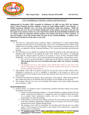
Base - 2098-9536Head - 2098-9201,2098-9202,2098-9203,2098-9208,Base - 2098-9536Head - 6r2098::576LlpowersourceIi-l&Base - 2098-9536Head - 6ElkLlLlwL2L224 VDCEOL Relay2098-9735or2098-9739rLm3IL2. 1x1Relay2096-9737(See Note 3)N/CN/OSeeBlkNote I- -12Notes: 1.2.3.4.5.6.Note51ElkRefer to wiring diagrams (841-687) provided with system panel for proper panel connections.If used, remote LED (2098-9808) is polarized; observe color-coded wiring. DO NOT USE RELAY if LED isDO NOT USE REMOTE LED when relay (2098-9737) is used.Aux. alarm contacts -form C-eachrated 1A @ 24VDC or 115VAC, resistive.Aux. alarm contacts - two form C -each rated 3A @ 24VDC or 115VAC, resistive.Refer to wiring diagrams provided with system panel for proper end-of-line resistor value.2098-9536 BASE CONNECTIONSBackup 2ISeeNote3-II”ListedSimplexFire AlarmControlPanel2120,4001,4002,4020,or4100 Primary1seeNote 2Base - 2098-9637Head - 2REBase - 2098-9637Head - 2098-9201,2098-9202,2098-9203,2098-9208,Head - 8qr9576Notes: 1. Refer to wiring diagrams (841-687) provided with system panel for proper panel connections.2. If used, remote LED (2098-9808) is polarized; observe color-coded wiring.3. It is recommended that the primary-l and the backup-2 lines be in separate wire runs and in compliancerequirements.2098-9637 BASE CONNECTIONSFOR STYLE D (FORMERLY CLASS A) INITIATE CIRCUIT5Technical Manuals Online! - http://www.tech-man.com2092576with local
JNoteListedSimplexFire AlarmControlPanel2120,4001,4002,1020,or4100 3Head - 2098-9201,2098-9202,2098-9203,2098-9208,Head - 20989201,2098-9202,2098-9203,2098-9208,Head - 098qr9576209E9576Notes: 1. Refer to wiring diagrams (841-687) provided with system panel for proper panel connections.2. If used, remote LED (20989808) is polarized; observe color-coded wiring.3. Refer to wiring diagrams provided with system panel for proper end-of-line resistor value.2098-9637 BASE CONNECTIONSFOR STYLE B (FORMERLY CLASS B) INITIATE CIRCUITBackup 2rI II---- -Primarv 1IIIIIIIIcListedSimplexFire AlarmControlPanel,2120,4001,4002,4020,or4100 See Note4Aux. Relay ContactsRated 1 A (1124VDCOr 115VAC ResistiveBase - 2098-9637Relay Module - 2098-9738Head - lay ModuleSee Note 3Or2098-9576Notes: 1.2.3.4.Refer to wiring diagrams (841-687) provided with system panel for proper panel connections.If used, remote LED (2098-9808) is polarized; observe color-coded wiring.When wiring relay to base, remove resistor (black wire) from base terminal 53. Wire only one base/relay per initiate circuit.For Style D (formerly Class A) initiate circuit, wire per dotted lines and do not use EOL resistor. If Style B (formerly ClassB) initiate circuit, refer to wiring diagrams provided with system panel for proper EOL resistor value.5. For Style D (formerly Class A) wiring, it is recommended that the primary-l and the backup-2 lines be in separate wireruns and in compliance with local requirements.BASE AND RELAY CONNECTIONS20989637 WITH 20989738FOR STYLE B (FORMERLY CLASS B) OR STYLE D (FORMERLY CLASS A) INITIATE CIRCUIT6Technical Manuals Online! - http://www.tech-man.com
Backup 2nII----eII ;IseeNote1-----Primary 1 -ilListedSimplexFire AlarmControlPanel2120,Aux. Relay ContactsRated 1 A ((I 24VDCOr 115VAC ResistiveBlk4001,4002.020, or 4100 Base - 2098-9211Relay Module - 2098-9738Head - 62098-9738Relay ModuleSee Note 3Notes: 1.2.3.4.Refer to wiring diagrams (841-687) provided with system panel for proper panel connections.If used, remote LED (2098-9808) is polarized; observe color-coded wiring.When wiring relay to base, cut JW. Wire only one base/relay per initiate circuit.For Style D (formerly Class A) initiate circuit, wire per dotted lines and do not use EOL resistor. If Style B (formerly ClassB) initiate circuit, refer to wiring diagrams provided with system panel for proper EOL resistor value.5. For Style D (formerly Class A) wiring, it is recommended that the primary-l and the backup-2 lines be in separate wireruns and in compliance with local requirements.BASE AND RELAY CONNECTIONS2098-9211 WITH 2098-9738FOR STYLE B (FORMERLY CLASS 8) OR STYLE D (FORMERLY CLASS A) INITIATE CIRCUITBackup 2ISeeNote3r!” Primary1zzrListedSimplexFire AlarmControlPanel2120,4001.4002.4020, or 4100 CmNntr34 AnSee. . RedNote2/-sWhtlBlk/ Base - 20989211Head - Head - 6Notes: 1. Refer to wiring diagrams (841-687) provided with system panel for proper panel connections.2. If used, remote LED (2098-9808) is polarized; observe color-coded wiring.3. It is recommendedthat the primary-l and the backup-2 lines be in separate wire runs and in compliancerequirements.2098-9211 BASE CONNECTIONSFOR STYLE D (FORMERLY CLASS A) INITIATE CIRCUIT7Technical Manuals Online! - http://www.tech-man.comHead - 6with local
4SeeNote 1miListedSimplexFire AlarmControlPanel2120,1001,40024020, or4100 Base - 2098-9211Head - 6SeeNote3Base - 2098-9211Head - 6Head - tes: 1. Refer to wiring diagrams (841-687) provided with system panel for proper panel connections.2. If used, remote LED (2098-9808) is polarized; observe color-coded wiring.3. Refer to wiring diagrams provided with system panel for proper end-of-line resistor value.2098-9211 BASE CONNECTIONSFOR STYLE B (FORMERLY CLASS B) INITIATE CIRCUITSeeNoteSeelote 1ListedSimplexrire AlarmControlPanel2120,001,4002,4020, or4100 Notes: 1.2.3.4.5.EOLResistor(if used)RedSeeNote2I,; ---- :Aux. Relay Contacts, EachRated 1 Amp at 30VDC or0.5 Amp at 12OVAC, ResistiveBase-2098-9637Relay ,2098-9208,or2098-9576I2098-9827 Relay ModuleSee Note 3Refer to wiring diagrams (841-687) provided with system panel for proper panel connections.If used, remote LED (2098-9808) is polarized; observe color-coded wiring.When wiring relay to base, remove resistor (black wire) from base terminal S3. Wire only one base/relay per initiate circuit.For Style D (formerly Class A) initiate circuit. wire per dotted lines and do not use EOL resistor. If Style B (formerly Class B)initiate circuit, refer to wiring diagrams provided with system panel for proper EOL resistor value.For Style D (formerly Class A) wiring, it is recommended that the primary-l and the backup-2 lines be in separate wireruns and in compliance with local requirements.BASE AND RELAY CONNECTIONS2098-9637 with 2098-9827FOR STYLE B (FORMERLY CLASS B) OR STYLE D (FORMERLY CLASS A) INITIATE CIRCUITaTechnical Manuals Online! - http://www.tech-man.com
EOLResistor(if used) mcListedSim lexF onfrIrnIiIPanel2120,4\;204;;2( )RedVi0BlkBlu4106 -WhtiBlkjGV.’Base-2098-9211Relav 2098-9208,-5Nii4c-5 N/OAux. Relay Contacts, EachRated 1 Amp at 30VDC or0.5 Amp at 1 POVAC, Resistive209:9576Notes: 1.2.3.4.5.2098-9827 Relay ModuleSee Note 3Refer to wiring diagrams (841-687) provided with system panel for proper panel connections.If used, remote LED (2098-9808) is polarized; observe color-coded wiring.When wiring relay to base, cut JW. Wire only one base/relay per initiate circuit.For Style D (formerly Class A) initiate circuit. wire per dotted lines and do not use EOL resistor. If Style B (formerly Class B)initiate circuit, refer to wiring diagrams provided with system panel for proper EOL resistor value.For Style D (formerly Class A) wiring, it is recommended that the primary-l and the backup-2 lines be in separate wireruns and in compliance with local requirements.BASE AND RELAY CONNECTIONSLIMITATIONS2098-9211 WITH 20989827FOR STYLE B (FORMERLY CLASS B) OR STYLE D (FORMERLY CLASS A) INITIATE CIRCUITOF SMOKE DETECTORSThe smoke detectors used with these bases are designed to activate and initiate emergency action, but will do soonly when used in conjunction with other equipment. They are designed for installation in accordance with NFPAstandards 72-l 990 and 72E.Smoke detectors will not work without power. AC or DC powered smoke detectors will not work if the power supplyis cut off for any reason.Smoke detectors will not sense fires which start when smoke does not reach the detectors. Smoke from fires inchimneys, in walls, on roofs or on the other side of closed doors may not reach the smoke detector and alarm it.A detector may not detect a fire developing on another level of a building. For this reason, detectors should belocated on every level of a building.Smoke detectors have sensing limitations, too. Ionization detectors are better at detecting fast, flaming fires thanslow, smoldering fires. Photoelectric detectors sense smoldering fires better than flaming fires. Because firesdevelop in different ways, and are often unpredictable in their growth, neither type of detector is always best, and agiven detector may not always provide warning of a fire. In general, detectors cannot be expected to provide warningfor fires resulting from inadequate fire protection practices, violent explosions, escaping gases, improper storage offlammable liquids like cleaning solvents, other safety hazards, or arson.Smoke detectors cannot last forever. Smoke detectors contain electronic parts. Even though detectors are made tolast for many years, any of these parts could fail at any time. Therefore, test your smoke detector system per NFPA72E & 72H at least semi-annually. Clean and take care of your smoke detectors regularly.9Technical Manuals Online! - http://www.tech-man.com
Technical Manuals Online! - http://www.tech-man.com
Technical Manuals Online! - http://www.tech-man.com
PER-21 -007 (575285)Ed 2 93Technical Manuals Online! - http://www.tech-man.com
Simplex publication "Common Code Requirements For Fire Alarm Systems" - Publication No. FA2-91-010. For additional information, refer to NFPA 72 E and the NEMA Guide For Proper Use of System Smoke Detectors. . Simplex Fire Alarm Control Panel 2120, 4001,4002, 4020,or4100 see Note 2 see RE Base - 2098-9637 ' Note2 Base - 2098-9637 Head .