Transcription
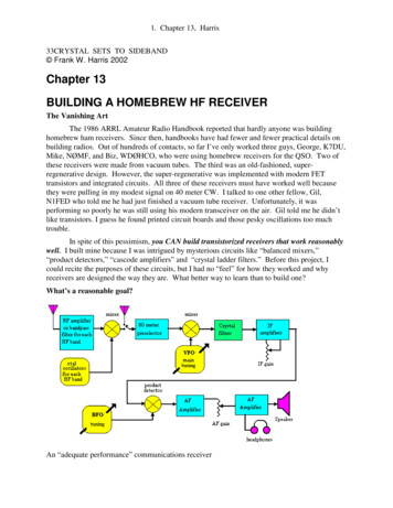
1. Chapter 13, Harris33CRYSTAL SETS TO SIDEBAND Frank W. Harris 2002Chapter 13BUILDING A HOMEBREW HF RECEIVERThe Vanishing ArtThe 1986 ARRL Amateur Radio Handbook reported that hardly anyone was buildinghomebrew ham receivers. Since then, handbooks have had fewer and fewer practical details onbuilding radios. Out of hundreds of contacts, so far I’ve only worked three guys, George, K7DU,Mike, NØMF, and Biz, WDØHCO, who were using homebrew receivers for the QSO. Two ofthese receivers were made from vacuum tubes. The third was an old-fashioned, superregenerative design. However, the super-regenerative was implemented with modern FETtransistors and integrated circuits. All three of these receivers must have worked well becausethey were pulling in my modest signal on 40 meter CW. I talked to one other fellow, Gil,N1FED who told me he had just finished a vacuum tube receiver. Unfortunately, it wasperforming so poorly he was still using his modern transceiver on the air. Gil told me he didn’tlike transistors. I guess he found printed circuit boards and those pesky oscillations too muchtrouble.In spite of this pessimism, you CAN build transistorized receivers that work reasonablywell. I built mine because I was intrigued by mysterious circuits like “balanced mixers,”“product detectors,” “cascode amplifiers” and “crystal ladder filters.” Before this project, Icould recite the purposes of these circuits, but I had no “feel” for how they worked and whyreceivers are designed the way they are. What better way to learn than to build one?What’s a reasonable goal?An “adequate performance” communications receiver
2. Chapter 13, HarrisMy receiver is based on the “High Performance Communications Receiver” designed byW7ZOI and K5IRK described in most of the annual ARRL Handbooks in the 1980s. In myopinion “High Performance” is optimistic, but certainly “adequate performance” is realistic. Idefine adequate sensitivity and noise figure to mean that I can hear the DX and QRPs that otherstations are working. Before I built the receiver described here, I often had the impression I washearing only the loudest signals. For me, adequate selectivity means that it's good enough forCW QSOs in the evening on 20 and 40 Meters. On these bands there are often dozens of narrowCW signals operating within a few hundred Hertz of each other. With a 10 KHz bandpass, youmay hear many stations simultaneously and not be able to copy any of them.Adequate sensitivity will allow you to hear most QRP signals. I believe that 45 years agohardly anyone had receivers that were “adequate” for QRP contacts. When I was a novice, myfirst transmitter was a 7-watt homebrew for 40 and 80 meters. I know it worked OK, because Italked to my novice buddies around town. Unfortunately I hardly worked anyone outside oftown. It wasn’t until I bought a 50-watt commercial kit, just like all the other novices, that I wasable to talk to all the same stations my buddies were working. I was still using the same dipoleantenna, so I can only assume the improvement was the extra power.The sensitivity of the receiver described in this chapter is well under 0.5 microvolt on 80meters and lower bands that have no RF preamplifiers. On the upper bands where the receiverhas preamplifiers I could l hear a calibrated signal source at 0.02 microvolts. Wow! No wonderI can hear those QRPs! In the old days sensitivity less than 1 microvolt was considered hot stuff.Another issue is adequate stability. When your receiver is equipped with sharp crystalfilters, it is vital that the VFO and crystal oscillators are stable enough that the signals you'relistening to do not drift in and out of your passband. If you have built a VFO like the onedescribed in chapter 10, you will have no drift troubles.Does it have to be so complicated?Looking at the block diagram above, each one of those blocks represents one to threetransistor stages. The front-end converter has three transistor stages for each separate HF band.That means you need to build about 20 transistor amplifier or oscillator stages for the convertersto cover all the bands. You’re probably wondering if there isn’t some simple receiver you canbuild that will get you on the air rapidly. The best news is that you can build the above receiverin stages. The core of the all-band HF receiver is a quality 80 meter receiver. You can build thatfirst, then at least you’ll be in business on 80 meters. In the beginning you can also do withoutthe loudspeaker and multiple crystal filters. After you have a functioning receiver, you can addfeatures and the converters to hear the other hambands.Yes, you can build a less complicated receiver, but I doubt it will “adequate.” My directconversion receiver in chapter 7 worked well, but was not selective enough. There are modernsuper-regenerative receiver designs with two or three integrated circuits that MAY be pretty good,but I haven’t built one, so I’m not convinced. Chapter 14 describes a vacuum tube regenerativereceiver that was great fun to build and quite good for listening to foreign short wave broadcaststations. Unfortunately, it was NOT selective and sensitive enough for ham communications. Insummary, YES, a decent ham receiver does have to be complicated.
3. Chapter 13, HarrisA homemade ham receiver built in 1967A homebuilt ham receiver from 35 years ago is shown above. It has 11 tubes, a simplecrystal filter and covers 80 through 10 meters. It doesn’t cover the WARC bands. Yes, it worksOK. But compared to the all-transistor receiver described in this chapter, it is insensitive, noisyand has poor selectivity.Being realistic, any receiver you build probably won’t match the performance of highend, commercial rigs. But every time your receiver brings in DX on a new band or whenever youconquer one of the dozens of glitches you will encounter, you’ll have a thrill and pride you’llnever get from a commercial rig. If you decide to build your own version of the W7ZOI / K5IRKreceiver, I recommend you find a copy of an old ARRL Handbook from the 1980’s and Xeroxtheir original descriptions. You’ll find they built most circuit blocks differently than I did.Going back to the original description may give you some useful ideas. Perhaps their versionwill work out better for you.PLANNING YOUR RECEIVERSuperhetrodynes offer crystal filters for CWA superhetrodyne uses a mixer to produce a constant intermediate radio frequency (IF).This intermediate frequency signal is always the same so it can be filtered with fixed crystals ormechanical filters to establish bandpass widths for CW and upper and lower SSB. Before youcommit to any design, make sure you can buy the critical parts you need, especially the crystal ormechanical filters for your IF. For example, many receiver designs use a 455 KHz IF.Unfortunately, I have yet to find an easy source for 455 KHz crystals for building filters and
4. Chapter 13, HarrisBFOs. Consequently, I have avoided this frequency. Among homebuilt ham receivers the mostcommon IF frequency seems to be 9 MHz.Why not single conversion?I had always wondered, “Why are homebuilt all-band HF receivers almost always dualconversion?“ It turns out that the fundamental challenge of homebuilt receivers and transmittersis building a stable VFO. Yes, you can build a reasonably stable VFO, but homebrew VFOsusually don’t have much tuning range. 0.5 MHz is typical. And, in order to drift as few Hertz aspossible, the VFO needs to be relatively low frequency. Homebrew VFOs are usually in therange of 2 to 7 MHz. The disadvantage of a low frequency VFO is that its harmonics will appearas one or two loud whistles on some upper HF ham bands.Compared to the practical VFO range of 2 to 7 MHz, the HF spectrum is huge, 1.8 to 30MHz. Right away one can see that a homebrew direct conversion 10-meter receiver is difficultbecause it needs a stable VFO that will tune 28 to 29.7 MHz. This problem can be solved by“converting“ the VFO oscillator up to 28 MHz using a crystal controlled oscillator and a mixerplus 28 MHz filter/amplifiers. This complexity ruins the simplicity of direct conversion. Ifyou’re going to operate above 40 meters, you may as well build dual conversion like the rest ofus.How do modern receivers do it?Modern receivers use integrated circuit frequency synthesizers to generate VFO signalsanywhere they like. Sometimes modern HF receivers escape from artifact images and harmonicsby using an IF frequency way up in the VHF range. In addition, after the initial mixer stage,some commercial receivers use multiple conversions to get the signal back down to an audiooutput. At each conversion stage, different kinds of filtering are applied. For example, theYaesu FT1000MP has four down-conversions from an 89 MHz IF. (!) This includes the digitalsignal processor with its 32 KHz input.In a superhetrodyne the VFO interacts with the incoming RF signals to produce anintermediate (IF) frequency. A 5 MHz VFO implies that the IF is going to be within 5 MHz ofthe band or bands it covers. Such a receiver might cover 28 MHz, but that would imply an IF of23 MHz or possibly 33 MHz. The lower bands would be out of range unless the VFO could betuned many MHz. Consequently, a single conversion homebrew superhetrodyne can only coverone band well, and can’t possibly cover the whole spectrum.In some old ham designs the VFO tuned 5.2 to 5.7 MHz. They used a 1.7 MHz IF andeither subtracted or added the IF to the VFO frequency to cover either 80 or 40 Meters.Specifically, 5.7 MHz minus 1.7 MHz 4.0 MHz and 5.3 MHz plus 1.7 MHz 7.00 MHz.)
5. Chapter 13, HarrisHomebuilt all-band dual conversion HF ham receiverStart with a single band, single conversion superhetrodyneBegin by building the best single-band receiver you can. The core of my receiver tunes80 Meters. To cover the other eight HF bands, separate crystal controlled converters convert thesignals down (or up) to 80 meters. This makes the receiver “dual conversion” on every bandexcept 80 Meters. In the old vacuum tube days each homebuilt amplifier stage was designed towork on several bands. This meant that the front panel of a 1970 homebrew receiver usually hada bunch of tuning knobs to tweak each stage. Today, a transistor amplifier or mixer stage isphysically tiny, so it’s practical to build a separate converter and amplifier pre-tuned for eachband. My experience was that building the converters to translate the bands to 80 meters wasrelatively easy. Unfortunately, building a decent 80 meter core receiver was much harder.Maybe with the help of this chapter, you’ll find the core receiver easier to build than I did.My 80-meter receiver has a 9 MHz IF. 9.00 MHz crystals are available for less than 1from Digi-Key and Mouser. The low price is important because, depending on your filter plans,you may need as many as 11 or more 9 MHz crystals. The downside of 9.00 MHz was that I hadto wait months for the crystals to arrive.An 8 MHz IF wasn’t such a good ideaAt first I used the more common 8.0 MHz crystals. Unfortunately, to receive 4.0 MHz,the VFO had to tune 4.0 MHz. I expected the 4.0 MHz VFO signal would be “a little birdie” thatwould mark the high end of the band. I thought this “edge-of-band marker” would be kind of
6. Chapter 13, Harrisconvenient. Instead, the “birdie” was more like a screaming siren that overwhelmed the IF andmade the upper end of the 80 meter ham band unusable. So when the 9.0 MHz crystalseventually arrived, I rebuilt everything for 9 MHz. Now the VFO (the big tuning knob on theabove receiver) tunes 5.0 to 5.5 MHz to cover 4.0 to 3.5 MHz. That is, 5.0 MHz 4.0 MHz 9.0 MHz. Of course the BFO frequency also had to change from 8 MHz to 9 MHz.An unusual adventureOnce your receiver begins to work, you’ll have interesting glitches. Until I got my 80meter preselector filter working, I usually heard rap music from my local 1190 AM radio. Also,the 31 meter shortwave band is just above the 9 MHz IF. Before it was aligned, I was hearingsermons from HCJB in Quito, Ecuador. Later, my 20 meter converter was overwhelmed by Dr.Scott, a Los Angeles evangelical minister, who preaches on 13.8 MHz. Once I had my modulestuned and sealed, Dr. Scott and his friends were silenced. Actually, I got a kick out of theseproblems.Building a receiver revived my interest in shortwave listening. I’ve had shortwave radiossince I was a kid. Some of them, like my Army surplus Collins R-388, were excellent. In spiteof this, I rarely listened when I wasn’t actively hamming. But once my homebrew receiver(s)began to work, I found myself exploring the bands as never before. For instance, on 80 meters Iwas amazed to hear hams from all over the continent. I had heard about guys who work DX andearn WAS certificates (Worked All States) on 80 meters, but I never really believed it. I haveeven worked QRP stations on 80 meters. 80 meters is usually so noisy, I didn’t know that waspossible. Until this year, I had never heard “spy code stations” before. Some of them have anannouncer reading apparently random letter groups, but most of them are CW “spy stations”sending Morse code 5 letter groups, just like the WWII Enigma signals. As I built converters foreach of the HF bands, it was like hearing them for the first time. The “WARC bands” wereinteresting because they were near to shortwave broadcast bands I hadn’t listened to in years.Building with modulesAside from the need to shield circuit blocks from one another, a homebrew receiver witha single big board full of discrete components has another problem. If you build the whole thingat once without buying a kit and pre-cut board, I guarantee it won’t work. To make homebrewstuff that works, you have to develop your own technology based on parts can get and circuitsyou understand. This was a different mind set for me. Rather than “building a receiver,” I hadto lower my sights and build one circuit at a time, e.g., “an oscillator,” “a mixer,” “an audioamplifier,” etc. Then I put the blocks together to complete my project. Some of these circuitblocks didn’t work the first time and I had to build a new block. There were various reasons theydidn’t work. Usually, I wasn’t able to buy the exact parts used in the circuits I was copying. Ormy craftsmanship or shielding wasn’t adequate. Sometimes I never did figure out why oneversion of a circuit block was superior to another.On rare occasions my circuits didn’t work because there were errors in circuit diagrams inQST magazine or in the handbooks. I found some serious errors in my 1979 Handbook and aminor one in my 1998 edition. Perfect editing is not possible, so we shouldn’t expect it.By building my receiver on separate little shielded modules for each circuit block, I couldreplace a circuit block whenever I managed to build an improved version. Otherwise, I would
7. Chapter 13, Harrishave ruined the whole big board. If painstaking R & D is new for you, prepare for a long battle.On the other hand, you’ll learn a lot and victory will be especially sweet.Mechanical constructionHomebrew receivers should be built in big cabinets. That way there’s lots of room to addfeatures and swap modules. The table in my shack is small, so I shoe-horned my receiver into afairly compact package. In general, roomy boxes with lots of panel space are a better idea. Mylong-range dream is to recycle my receiver modules into a larger cabinet. Eventually I want toadd DSP, frequency counters, phase lock loops and other goodies that intrigue me. With a bigenough chassis, a receiver can grow and improve continually.The receiver modules are interconnected with phono plugs and skinny coax.Metal boxes shield each circuit blockA basic reason for building a receiver in metal-shielded modules is that capacitivecoupling from one circuit block to the next can degrade performance. For example, my first 80meter receiver module was built on one board. A crystal filter determined the selectivity. I madetwo “plug-in” crystal filters so I could use different filters for CW and for SSB. Using my 20meter converter, I was tuning around 20 meters one day. I could hear lots of hams, but I wasbothered by poor sensitivity and poor selectivity. I thought, “What’s wrong with this receivertoday?” I soon discovered there was no filter at all plugged into the 80 meter receiver board.What I was hearing was just stray coupling between the mixer and the IF amplifier. Amazing!So if you want band-pass filters with 50 dB skirt attenuation, you’re going to need at least thatmuch isolation between the stages. That means you need metal shields between all stages, coaxinterconnects and lots of bypass capacitors.The metal-shielded modules can be small circuit boards mounted in commercial boxes.
8. Chapter 13, HarrisWhat I usually do is make shallow rectangular boxes out of pieces of two-sided circuit boardmaterial soldered together. The circuit is then carved into the floor of the box using small woodcarving chisels. The press-fit lid of the box is made from thin sheet aluminum folded over thecorners of the PC board box.Egg carton construction of the “mother board” of an 80 meter receiverThe compartment on the left is the product detector and audio amplifier. The large areain the center is the IF amplifier and AGC. The two modules on the right are the mixer and anoptional RF pre-amplifier for the crystals.If you plan on having more than one circuit block on the same board, you can isolatecircuit blocks from each other using circuit board barriers soldered in place. The result is “eggcarton construction.” Power can be routed between compartments using feed-through capacitors.If you suspect that a circuit block might not work, then wire your circuit on a separate square ofPC board, then mount it on the floor of the desired compartment. All of these techniques areillustrated above. The IF amplifier in the center compartment is on a separate PC board.Shielded modules and shielded cable interconnectsFor connections between stages I use thin RG-174 coax and phono plugs. Right anglephono plugs are not designed for RF and have too much capacitance. However, they’re cheap,available, easy to wire, and don't take up too much room. I don’t pretend that phono plugs areOK for 6 meters and VHF. I got some feel for their frequency limit when I discovered thatswitching from a phono plug to a UHF PL-259 on my 50 watt transmitter amplifier vastlyimproved performance on 10 meters. So far, I haven’t seen any problems when working withlower frequencies and far lower power levels. Fortunately, receivers have tiny currents and lowvoltages. Most phono plugs have plastic bodies. That means that about 3/8 inch of the centerconductor is not be shielded. For my crystal filters I used metal-bodied phono plugs that are atleast a slight improvement.TV cable connectors are electrically superior to phono plugs, but they are dreadfullyintermittent. Personally, I’ve found them unusable and I wish the TV industry would junk them.Proper RF connectors like BNC, SMA or TMA cost 2 - 6 each. Some of them are hard to
9. Chapter 13, Harrisassemble and your receiver could easily contain 300 worth of “proper” connectors. Also, mostof these connectors are too long to fit gracefully in a small receiver. Right-angle phono plugs arequite short and quite cheap. Long live phono-plugs!Use plastic knobsOne odd little problem I encountered was that touching the metal control knobs or thefront panel caused scratchy noise in the headphones when I listened on the higher bands. Yes,the metal panel was grounded and the chassis was wired to the station ground. The stationground is a heavy 12 gauge wire that grounded all the chassis’s to a copper metal pipe next to thestation. I don’t really have explanation for this, but I switched from metal to plastic knobs andthe annoying scratchy noises improved.Bottom view of the receiverBand switching and power suppliesThe precision power supply for the VFO is at the top right. The low drop-out regulatedsupply for the rest of the receiver is at the bottom right. These are the same circuits used earlierwith the VFO & QRP transmitter modules. The band-switch is the multi-wafer ceramic switchon the left. The black wires on the left are skinny coax that interconnect the inputs and outputsof the converters for every ham band except 80 meters. It is desirable to cover the bottom with ametal plate to help keep stray signals out of the power leads.80 Meter input preselectorThe core of the receiver is an 80 meter single-conversion superhetrodyne. The “frontend” of this receiver is a mixer. No RF pre-amplifier is needed on 80 meters because, if thereceiver works well, then the atmospheric noise coming in from the antenna will be louder thanthe receiver internal noise. In this situation an RF amplifier won’t help. However, the mixerdoes need a sharp bandpass “preselector” filter to keep out the low frequency AM radio and limitthe input signals to 3.5 to 4.0 MHz. It’s especially vital to filter out AM broadcast stations.These stations put big voltages on the antenna and tend to overwhelm the mixer unless they arewell attenuated.
10. Chapter 13, HarrisThe mixer subtracts the VFO frequency, (5.0 to 5.5 MHz) from the IF frequency, (9MHz), to tune 80 meters, (3.5 to 4.0 MHz). The two inputs to the mixer are the VFO signal andthe antenna signal. When I first examined the 1986 ARRL design, I was disappointed to see thatthe pre-selector had a primitive variable capacitor that the operator was supposed to tune formaximum gain for a particular part of the band. After all, the bandpass filters for the other HFbands were fixed and not accessible from the front panel. I attempted to build my own fixedbandpass filter, but my filters had too much attenuation (poor sensitivity) and sometimes let inAM broadcast stations - it was like listening to a crystal set.The recommended 80 Meter preselector filter for the core receiver mixer input.So I returned to the ARRL design with the 365 pF variable capacitor. It had so muchattenuation on 80 meters, I couldn’t hear a thing. I ran the ARRL circuit on a Spice program,and, according to Spice, it should have worked well. However, mine didn’t. Using trial anderror, I removed some parts and ended up with the circuit shown below. My filter works prettywell, although, according to my Spice program, it shouldn’t have. Sigh.My version of the 80 Meter preselector filter for the mixer inputI mounted the preselector in a shielded box up on the front panel where the peakingcapacitor was accessible. Someday, when I figure out how to build a better preselector, I shallreplace the whole module. On the positive side I found that the variable peaking capacitor isquite useful as an attenuator for receiving strong single sideband signals. That is, strong SSBphone signals are often much more intelligible when the preselector is mistuned and signalstrength is decreased.
11. Chapter 13, HarrisThe preselector is built in a little box up front behind the front panel.The variable frequency oscillator (VFO)The receiver VFO is the same as the 5 MHz transmitter VFO discussed in chapter 10.The big tuning knob controls the VFO. Actually, in superhetrodynes the VFO is usually called alocal oscillator. The range and stability of the VFO determine what VFO and IF frequencies arepractical. Like a transmitter VFO, a receiver VFO should be stable to less than 5 Hz/ minutedrift, although less than 20 Hz will probably be OK.Unfortunately, if the VFO frequency is too low, it probably won’t span enough Hz tocover the bands you’re interested in. Notice that 10 meters is so huge, 1.7 MHz wide, that youmay have to cover it with multiple converters. So far, my receiver just tunes the first 500 KHz of10 meters, which includes all the CW activity. I guess I’ll worry about the rest when I get on 10meter SSB. The VFO frequency and its harmonics should avoid the ham bands as much aspossible. Frequencies with round numbers are best because they make calibration easy. Put allthese factors together and you’ll find your choices are actually fairly limited.In fact, once you’ve built separate transmitters and receivers and used them on the air, thedisadvantage of having to tune two VFOs makes it obvious why most modern rigs aretransceivers. When planning a homebrew receiver and transmitter, you might consider using acommon VFO modules. A common VFO would be a great help on the air. But, if you use justone VFO, you will have to master the 500 to 800 Hz send/ receive frequency-offset problem.Also, an isolation amplifier is needed to keep the cable connecting one to the other from loadingdown the receiver VFO. And finally, when used on the upper bands, each crystal oscillator in theconverter and each transmitter PMO must be on the corresponding frequencies in order for thereceiver to listen on exactly the same frequency used by the transmitter. This represents lots ofwork.
12. Chapter 13, HarrisA varactor tuned 5 MHz VFO. Tuning is accomplished with the big round potentiometer.Mixer magicThe purpose of a mixer is to translate the frequency of an incoming radio signal to aconstant intermediate frequency (IF) that can be amplified and filtered more easily. Mixerscombine a local oscillator sinewave with the incoming radio signal to make a composite signal.The new signal contains the original frequencies, plus the new sum and difference frequencies.Mixers intended for moving a VFO up to a high band were described in chapter 11. Mixers forthis purpose can be quite crude and will work well. Unfortunately, receiver mixers are muchmore difficult because the signal input can be so tiny.One way to look at mixers is that a big local oscillator sinewave keys the incoming RFsignal on and off, cycle by cycle. The lesson is that the local oscillator (the VFO tuning knob)must be a big signal while the RF input signals may be arbitrarily small.The ARRL Handbook presents six or eight different mixer designs made with discretediodes, inductors and transistors. However, in most ARRL receiver designs since the 1980’s, themixer is an integrated circuit or little canned assembly labeled “mixer.” I guess everyone elsewas having mixer trouble too, so they resorted to integrated circuits. Last year there was a simplereceiver project in QST that used an IC that contained both the mixer and the VFO. I’ll bet thesemarvels work fine, but the contents of these ICs are a mystery. Use one if you want.Mixers will give you lots of static. and squeals, howls and squawksSo far I’ve built four different mixer designs from discrete parts. First I built a classicbalanced mixer with ferrite cores and a hot carrier diode ring. When I turned it on, I heard loud,roaring static in the headphones. “Oh goodie!” I thought, “Listen to all that atmospheric static!It must be working!” I soon figured out that the static was coming from the mixer and the IFamplifiers and had nothing to do with the outside world. I had just learned a basic truth aboutmixers: Mixers aren’t just prone to generate “a little background noise.” They often producegigantic Niagara Falls noise that obscures everything coming in the antenna. However, once Ihad the mixer input levels and resonant circuits tuned up as best I could, the noise disappearedand I began to hear stations. Unfortunately, as I tuned across the band, there were loud whistleslike marker beacons every few KHz. In between the whistles, I could sometimes barely hear
13. Chapter 13, Harrisstrong stations. So much for diode ring mixers.A practical mixerThe only mixer that has worked well for me is shown above. All the others suffered fromnoise, “birdies” and usually insensitivity as well. My successful mixer is made from a dual gateMOSFET. Unlike diode mixers, the operation of this mixer is obvious. The dual gate mixer isessentially an ordinary tuned transistor RF amplifier. The radio signals come in on one controlgate. This modulates the large current passing from drain to source of the transistor. The smallvoltage on the control gate controls the large drain current thereby amplifying the original signal.A second input gate amplifies the local oscillator signal. The local oscillator signal is so strong itturns the drain to source current totally on and off, “chopping” the input RF signal into tinysegments. The big output current from the transistor becomes an amplified “mixture” of the twoinput signals. I originally used a tuned version of this mixer in which the transformer primarywas tuned with a capacitor to resonate at 9 MHz as shown above. That works OK, but is rathertweaky and subject to noise and birdies. I now prefer an untuned version (not shown above)which has slightly less gain, but isn’t so easily misaligned. Just use a CWS (Amidon) FT50-61ferrite core with 20 turns primary and 4 turns secondary.Because of the high gain of the MOSFET, the VFO sinewave signal can be lowamplitude, 1 volt peak, and still fully chop the radio signals on and off. In contrast, a diode ringmixer needs a big local oscillator signal, 12 or more volts peak, to chop the signal. Othertransistor mixer designs use junction FETs or bipolar transistors. These designs use the emitterresistor as the VFO input port. The emitter or source has no gain, so these designs also need biglocal oscillator signals.A small local oscillator signal is especially helpful for building the converters you willneed for each of the other nine HF bands. Each of these converters must work through its ownmixer. If the dual gate mixer were not used in the converters as well, each of the eight localoscillators you will build would need separate amplifiers to get the local oscillator signal up to 12volts peak. You could also put in a common, broadband pre-amplifier for the crystal oscillatorinputs to a common untuned mixer.
14. Chapter 13, HarrisAll dual gate MOSFETs are not equalAlas, a dual gate MOSFET mixer isn’t a guaranteed success either. When I f
The best news is that you can build the above receiver in stages. The core of the all-band HF receiver is a quality 80 meter receiver. You can build that first, then at least you'll be in business on 80 meters. In the beginning you can also do without the loudspeaker and multiple crystal filters. After you have a functioning receiver, you can add