Transcription
PrintPower searchPreviousNextREPAIR / REPLACE DECISION MAKING PRACTICESG Winsor & S BuncombeEnergy AustraliaSummary: In a large asset organisation the renewal of assets forms a significant portion of theongoing annual capital works programme. Over recent years there has been an increasing focus bythe energy regulators on evidence of prudent expenditure. The development of tools and processesthat provide this objective evidence has become essential for the support of modern assetmanagement practices. The approach taken by EnergyAustralia has been to develop conceptspresented at past ICOMS conferences into a working repair/replace model with a simple userinterface.This paper outlines the evolution of repair/replace decision making within EnergyAustralia byexploring the technical, financial and change management techniques required for practicalimplementation, and finally, reviews some practical examples via case studies.The model developed incorporates asset failure history to develop a view of the future risk offailure and total cost of ownership. It takes into account the realised and unrealised costs of theexisting assets, and compares these to the expected costs of the replacement asset to provide arecommendation for the decision maker.Keywords: Repair, Replace, Decision, Electricity,1INTRODUCTIONThe decision to repair or replace an asset can be an easy or difficult decision. Minor low cost failures on young assets andmajor failures of assets, particularly aged assets, are often very clear and easy decisions to make. But how should we addressfailures on assets that may be considered ‘mid-life’? An issue for the asset or plant manager is “How much can we justifiablyspend on repairing the asset or equipment before replacing it?”. There are often a number of technical issues involved, whichas engineers we have become competent to address, and deliver a range of possible technically feasible solutions. But how dowe assess the financial impacts of our solutions to arrive at a decision, particularly in terms of the asset economics and futurerisk costs?2ASSET MANAGEMENT ENVIRONMENTEnergy Australia operates it’s electrical network as a monopoly, and is subject to regulation by the Australian EnergyRegulator (AER). Therefore, at each regulatory determination EnergyAustralia needs to be able to demonstrate that theinvestment in our assets is prudent, and that money is not being ‘wasted’ on excessive asset renewal, or in continuing tomaintain or repair an asset when it is no longer prudent to do so.In developing and implementing our approach to asset management it was recognised that we would need to also develop a setof tools to assist the asset decision makers. The decision to repair or to replace an asset must incorporate the technical issues,risk costs and economics. Engineers are well schooled in the technical aspects, but often not in the economics and thequantification of risk into financial impacts.The work published in ICOMS 2002i by Buckland and Hastings, and in ICOMS 2004 by Hastings and Sharpii were used as thebasis for the development of firstly a transformer repair/replace model (as a proof of concept) followed by the development ofa generic model which could be used for any asset. These models were produced to assist the determination of the lowestfuture cost of ownership arising from the repair the existing asset or renew the asset decision, and to enable objective supportof the resulting decision.Since the model was going to form an essential part of our asset management toolkit, and likely to be reviewed and challengedby the AER, the decision was made to have the model independently reviewed. To do this we also elected to utilise a firm ofconsultants who had been previously used by the ACCC to review our 2004-2009 regulatory submission, with the objectivethat they not only independently check the model, but also review and challenge the model as if they were working for theICOMS Asset Management Conference, Melbourne 2007 Paper 025 Page 1
BackPower searchPreviousNextregulator. This provided a reportiii which we were able to use to ensure we addressed any likely issues before being challengedby the new regulator, but most importantly confirmed the validity of our approach and model implementation.3MODEL DEVELOPMENTThe development of the first repair / replace decision model and tool for power transformers quickly identified that there werea number of critical issues. These were:The method of calculation of the equivalent annual cost (EAC) for the existing and the new assets impacts the determinationof the spend limit The model is sensitive to the risk profile selectedOnce these issues were addressed, and the model independently checked and validated, a more generic repair /replace decisiontool was developed that could be used on any asset.3.1EAC Calculation considerationsThe determination of a spend limit is in itself fairly straight forward, and is described by Hastings and Sharp2at equation (1) oftheir 2004 ICOMS paper:Spend-Limit Remaining life of old machine x (Annualized cost of new item – Annualized cost of old item)(1)To calculate the annualised cost, or EAC, of an asset at any age during it’s life, the equation derived by Buckland andHastings1 can be used.i n i n i inEAC A p G (i ) p S (n) / p i 1 i 1 (2)whereA Acquisition costp Discount factor {p 1/(1 r)}r capital discount ratei Year of life from 1 to .n.G (i) M (i) R (i)M (i) Maintenance cost and losses in year .i.R (i) Risk cost in year .i.n Age of asset at disposalS (n) Net disposal value at year .n.(resale value less expenses)Similarly if we consider the future EAC of an existing asset of age k years, which is repaired at a cost B, it can be determinedusing the following adjustment to the above formula:EACexistingi n i n i in B p G (i ) p S (n) / p i k i k (3)whereB Repair Costk current age of asseti Year of life from k to .n.In both cases it is clear that the risk cost in each year, ie the risk profile of the asset, will be required to determine the EAC atany given age.3.2Risk profile considerationsThe determination of the risk profile was identified as a significant input from early trials of the model. The reason for this inthe case of power transformers was that the risk costs were generally equal to the installed asset costs, and in some casessignificantly greater when secondary damage costs to adjacent assets are considered.The establishment of a linear risk profile starting at a given age was initially proposed and tested, with the analyst providing 1,2 and 5 year future risk estimates which were then subject to linear regression to project a future risk. Whilst this approachwas found to be relatively simple, the problems with this method were it is very subjective, it was difficult to objectivelysupport the risk points used, and the risks into future years could end up un-realistically high . Multiply this high degree ofsubjectivity with the large risk costs, and it clearly would be a significant component in the EAC determination when usingequations 2 or 3 (above). Therefore better means of incorporating the future risk of the asset needed to be established, and itwas decided to base this upon the statistical failure rates of the transformers.ICOMS Asset Management Conference, Melbourne 2007 Paper 025 Page 2
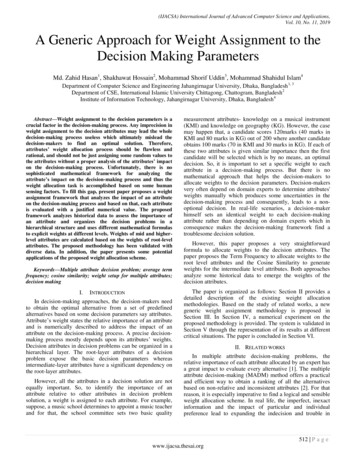
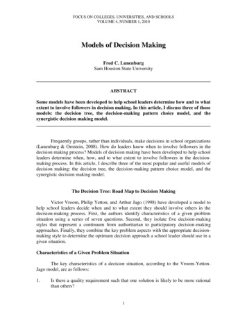
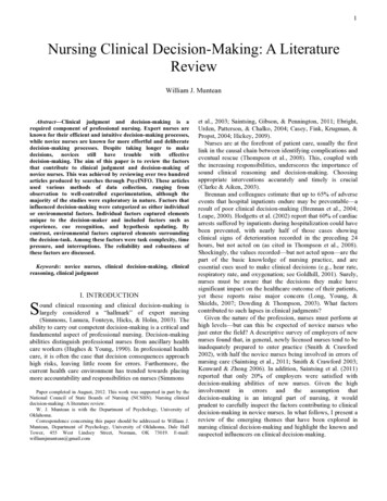
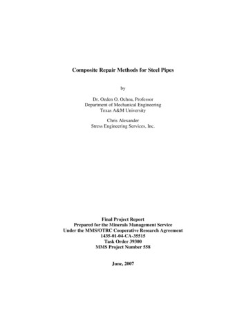
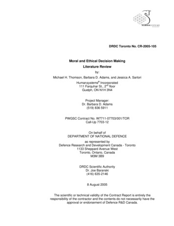
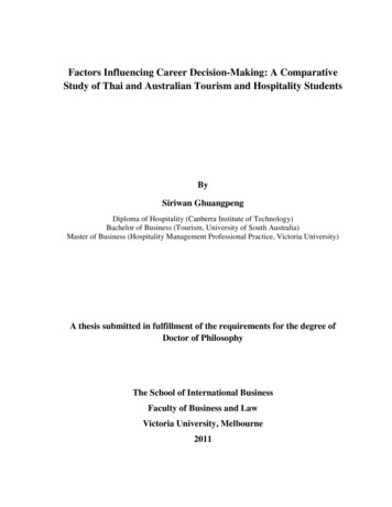
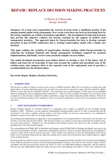
BackPower searchPreviousNextThe development of the model was paused whilst statistical analysis of our sub-transmission and zone type transformers wasundertaken. This analysis was grouped by voltage and design technologies to produce the failure probability density andcumulative density curve shown respectively in figure 1 and figure 2 below.Transformer Major Failure - Probability Density Vs 3343728312225191316710140.0%Years132kV Bushing ST66kV Bushing33kV Zone Bushing33kV Zone Endbox132kV Bushing ZoneFigure 1Transformer Major Failure - Cummulative Risk vs 2519221316710140%Years132kV Bushing ST66kV Bushing33kV Zone Bushing33kV Zone Endbox132kV Bushing ZoneFigure 2Now we could link our future risk probability with our asset type and age. The next challenge was to determine therecommended replacement age.3.3Determining the recommended replacement ageIn section 4 of their ICOMS 2004 paper, Buckland and Hastings described how to determine the recommended replacementage using the cumulative undiscounted costs, and this is shown in figure 3 below.ICOMS Asset Management Conference, Melbourne 2007 Paper 025 Page 3
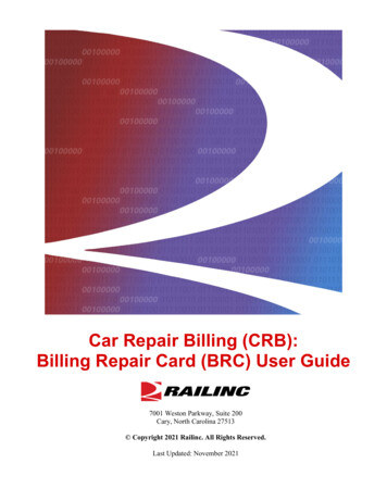
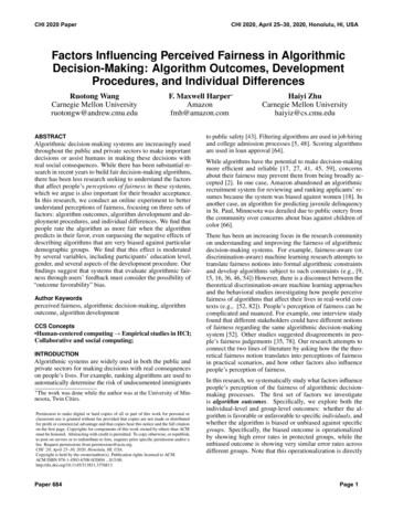
BackPower searchPreviousNextCosts withunrealisedriskCosts withrealised riskCumulative CostCumulative Cost vs AgeRealisedRisk- - - long runaverage costReplaceAssetAgeReplaceAssetFigure 3So to determine the optimum replacement age all you had to do was determine the tangent to the curve in figure 3, whichrepresents the lowest long run average cost per year, and read off the corresponding age. This is a simple process where themaintenance costs of the asset are not significant, and easily performed in a spreadsheet. However for real world assets this isnot so simple, as the cumulative cost ‘curve’ is not so smooth, as can be seen in figure 4 below. 3,500,000Existing cummulative costs with unrealised risk 3,000,000 2,500,000 2,000,000 1,500,000 1,000,000 7252321191715139117531 0yearFigure 4As can be seen, there are a number of potential ‘tangent points’. Clearly we need more than just mathematical analysis tomake a decision as there may be a case for not repairing the asset at it’s optimum recommended replacement age. Consider thecase in figure 5 below.ICOMS Asset Management Conference, Melbourne 2007 Paper 025 Page 4
BackPower searchPreviousNext 3,500,000 3,000,000Existing TX cummulative costsOptimum EAC - existing Tx 2,500,000 2,000,000 1,500,000 1,000,000 7252321191715139117531 0yearFigure 5In this case the optimum replacement age is the current age at 39 years, however there is another point which has almost anidentical long run average cost at 49 years. This age can be reached by reducing the scope of the repair work and deferring themaintenance due in yr 48 to the following year. The benefit of this solution, whilst not the economic optimum, is that it extendsthe transformer life to the retirement of the substation, and thus avoids unnecessary capital expenditure with an almost identicallong run average cost. Therefore the asset manager needs to combine analysis tools with an understanding of the businessneeds as well as the asset itself to be able to establish a sound decision for the future of the asset.44.1CASE STUDIES - TRANSFORMERSRepair/Replace Case Study – SURRY HILLS STS T1EnergyAustralia has a Sub-Transmission substation in the Surry Hills area of the Sydney CBD which has some uniquelogistical issues from the standpoint of replacing transformers. The substation was built in 1964 and houses four (4) 132 / 33kilovolt 120 MVA transformers in separate enclosures.Substation Tx EntranceTransformer RunwayThe transformers are approximately 36 years old and their condition is considered fair for their age. EnergyAustralia has an oiltesting regime where samples taken from the transformers are analysed to determine the dissolved gases contained in the oil.The chemical composition of the dissolved gases generally gives a good indication of any insulation deterioration which maybe occurring in the transformer. By trending the gases we can receive a picture of its condition and assume its remaining life.In 2003 the No.3 transformer was refurbished in situ by EnergyAustralia staff to repair significant oil leaks which wererequiring constant attention having to top up the transformer reservoir and also required the pump-out and removal of drainedoil from the oil interception tank. The repairs carried out included replacing all cork gasket seals, welding of the top plateflange, major overhaul of the tap-changer and clean-up of all excess oil from the transformer bay area.ICOMS Asset Management Conference, Melbourne 2007 Paper 025 Page 5
BackPower searchPreviousNextIn 2005, the oil leaks affecting the No.1 transformer were raised as a concern with records showing approximately 700 litres amonth being lost from the transformer seals. By this stage, EnergyAustralia had introduced a transformer review committee tooversee the condition of the ageing population and manage the most cost effective replacement solutions. A newRepair/Replace Model had been developed by our Operations Investment Group, and ratified by the committee. We decided touse it as a trial to assist with the repair/replace decision on the Surry Hills T1. The model was in its first stage of developmentwith a linear risk curve incorporated which had to be manually adjusted. (Later versions incorporate a specific risk model forthe transformer configuration as described previously).The details of the No.1 transformer and the measured characteristics of the oil sample taken are as follows:Manufacturer: ToshibaYear of Manufacture: 1969 Age: 36 yearsTap Changer Type: Reinhausen “F” TypeOil Electric Strength: 71kVWater Content: 13 ppmTotal Furans1: 0.48 ppmThe condition of the No.1 transformer was assessed as follows:The standard life of a power transformer according to the NSW Treasury Guidelinesiv is 50 years so we still had 14 years ofundepreciated value left in the asset registers for this transformer.The internal engineering consulting group reviewed the oil sample results and indicated this transformer showed minimal signsof deterioration of its insulation compared to other similar aged transformers so recommended, barring an unusual orunexpected event (like a 3 phase bolted fault in close proximity to the transformer), that the transformer winding should haveat least another 10 plus years of remaining life.The main issue was the major leaks in the transformer and the condition of the tap-changer. The Reinhausen type F tapchanger history was examined and the technicians interviewed to assess if there were any pending issues which may cause amajor refurbishment of the tap-changer which could ‘tip the scales’ towards a complete replacement. The feedback receivedwas that the tap-changer was in good condition, so we looked at comparing the cost of repairing the oil leaks under a majorrefurbishment capital plan.OUR OPTIONS1.Do NothingThe leaks coming from the No.1 transformer were significant (700litres per month) but were being contained by the oilbunding, interception tank and staff topping up the conservator once a month. The problem was the interception tank neededto be emptied each month. It could be extended to 2 months but if an incident occurred on any of the other oil equipment inthe substation the capacity of the tank could be compromised and then the oil would escape to the local stormwater drainagenetwork which eventually would reach Darling Harbour. The cost of pumping out the interception tank each month wasestimated at 2,000 so the annual cost was 24,000.During the times when the transformer is being topped-up the Surry Hills Sub-Transmission substation has to be reduced to anN level of reliability (ie there was no redundancy in the electrical network normally designed for N-1) with a consequentialincrease in the “System Risk Profile” for this duration. Usually the switching is carried out the evening before and the eveningafter the work so the duration of the transformer outage could be up to 18 hours in total each month.In addition, the do nothing option has a high likelihood of an incident impacting the environment which would resultin corporate and/or individual fines.To represent this scenario in the model we escalated the risk by increasing the consequential cost of failure to 1million.1The degradation of the paper insulation in transformers releases Furans, which is measured in transformer oil using DissolvedGas Analysis. The magnitude (in ppm) is an indicator of the level of degradation of the transformer winding cellulousinsulation. The higher the furans, the worse the condition of the insulation, with a level of 2 ppm being indicative of the onsetof significant insulation degradation.ICOMS Asset Management Conference, Melbourne 2007 Paper 025 Page 6
BackPower search2.PreviousNextRefurbish the TankAs the EA staff had some experience from the previous refurbishment of No.3 Transformer earlier we thought it to be alow risk to ask them to carry out the same work on the No.1 transformer. We first reviewed the current state of the No.3transformer leaks to see how successful their previous project turned out. Since completing the No.3 transformer therewere no signs of leaks from the many flanges, seals or welds. This outcome gave us a high level of confidence that theycould repeat the task on the No.1 transformer, which was a ‘sister’ to the previously repaired transformer. The supervisorand his staff were all still in the section and staff movements would therefore not affect the quality of the work asessentially they were the same crew.The scope of the work was set-out as follows:Timeframe: 30 daysManufacture new lid boltsWeld turrets if requiredWeld lidReplace bolts – lid & turretsReplace 132kV bushingsRemove and replace all other bushing gasketsRemove and replace all radiator gasketsRemove and replace flapper valve, pipe work and oil pump gasketsRemove and replace all hatch cover gasketsRemove and replace tap changer outer oil cylinder tank lid sealing gasketFilter oil and vacuum fill transformerSupply oil spill clean up materialsClean floor and cable ducts and dispose of soiled materialsCost including all materials and crane hire.The estimate for this work was 255,000.3.Replace the TransformerThe logistics of replacing the transformer was considered on site with the local supervisor, project manager and designmanager. The problems which would have to be addressed are numerous and local council and various governmententities would have to be co-ordinated to achieve the end result.The substation is built on a long block with adownward sloping access road. On the oppositeside of the street there are light commercialpremises mixed with terrace style domesticresidences. The street is lined with trees andvehicles are parked both sides of the street.ICOMS Asset Management Conference, Melbourne 2007 Paper 025 Page 7
BackPower searchPreviousNextThere has not been a transformer replacementcarried out at this substation since it was built.During the time EnergyAustralia has owned thesubstation there have been civil variationscarried out which has changed the levels of thetransformer entrance roadway and all thetransformers have been enclosed behind soundenclosures.SubstationRunwayT4T3TXT2T1Sloping DownThe cost of the replacement logistics was estimated at 548,000 excluding the value of the transformer, with a total estimatedinstalled cost of 1,748,000.Scenario AnalysisA number of scenarios were developed which tested both the sensitivity of the model and the estimated cost of the work.OptionNo.RefurbishCostExpected LifeafterRefurbishmentSignificant Costof FailureDoNothing1B1C1D1E 0N/A 1,000,000 255,000 300,000 323,000 324,00024 years24 years24 years24 years 250,000 250,000 250,000 250,000Risk 0 107,77241 .5;5.00.25;1.0;2.5;5.0 82,637 82,637 82,637 82,63759 years59 years59 years35 yearsRefurbRefurbRefurbReplaceThe primary parameters were entered into the model and the results assessed and entered into the above table.An example of the Do Nothing screen and graph is shown below:ICOMS Asset Management Conference, Melbourne 2007 Paper 025 Page 8
BackPower searchPreviousNext4.2SELECTED OPTIONThe difficult logistics of replacing a transformer on the site became a significant factor in the repair / replace decision. Theimmediate problem was the risk of an oil leak escaping the interception tank so a short-term solution was a primary objective.In developing the logistics required in replacing the transformer it became clear that it was going to take a number of years toundertake and co-ordinate this work, and as such provide no immediate relief to the current problems and associated risks.The sensitivity checking undertaken with the model provided us with a clear indication that the repair option was cost effectivesolution. This recommendation was presented to the Transformer Committee and the project approved. The repairs werecarried out and the leaks have now been addressed.5CONCLUSIONSThe development of a model as a tool to assist making the repair/replace decision has proved valuable from both an academicand a practical perspective. It has provided a more detailed understanding of the asset risks and assisted us to predict the futurein a way which can be objectively reviewed by our internal stakeholders, and our industry regulator.The worth of the approach has been demonstrated in the objective input to the decision making process, especially in whatwould of otherwise have been a very subjective decision. It helps provide the balance between the technical and the economicaspects and provides a valuable tool in our asset management toolkit.ICOMS Asset Management Conference, Melbourne 2007 Paper 025 Page 9
Back6Power searchPreviousBIBLIOGRAPHYMaintenance Requirements Analysis Manual, Energy Australia, 2000Winsor, Repair / Replace?: A Case Study in Decision Making for the End of Economic Life, IQPC – Life Extension of AgingAssets, Sydney 2006.7REFERENCESiBuckland & Hastings, The Replacement Decision for Long Assets, ICOMS 2002iiHastings & Sharp, Spend-Limits And Asset Management, ICOMS 2004iiiPB Associates, Review of Investment Decision Models - Transformer Repair or Replace, Energy Australia 2006ivNSW Treasury Policy Guideline “Valuation of Electricity Network Assets”, Draft May 2003ICOMS Asset Management Conference, Melbourne 2007 Paper 025 Page 10
ICOMS Asset Management Conference, Melbourne 2007 Paper 025 Page 3 The development of the model was paused whilst statistical analysis of our sub-transmission and zone type transformers was undertaken. This analysis was grouped by voltage and design technologies to produce the failure probability density and