Transcription
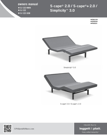
owners manual G-122 NWH G-122 G-122 USBS-cape 2.0 / S-cape 2.0 /Simplicity 3.0 ENGLISH SPANISH FRENCHSimplicity 3.0S-cape 2.0 / S-cape 2.0LPAdjustableBases.com
contentsAdvisory. 3Installation. 5Remote Control Function. 9Remote Control Programming. 10Power Down Operation. 13Troubleshooting. 16Accessories. 17Warranty. 18Spanish translation begins on page 20.La traducción en español inicia en la página 20.French Canadian translation begins on page 38.La traduction en Français débute à la page 38.If adjustable base does not operate or if parts are missing, call:1.800.888.3078
advisoryimportant informationREAD THE FOLLOWING INFORMATION CAREFULLY BEFORE USING THIS PRODUCTRead all instructions before usingFor optimum adjustable baseoperation, use a grounded, electricalsurge protection device (notincluded). Failure to use a surgeprotection device could compromisesafety or cause product malfunction.electrical ratingInput: 100-240VAC, 50/60Hz, 1.6A. Output:29VDC, 2A.electrical groundingThis product is equipped with a polarized orgrounded electrical power cord. The power cord willonly fit into a grounded, electrical surge protectiondevice (not included) or a grounded electrical outlet.warranty warningDo not open any control boxes, motors or remotecontrol devices (with the exception of the remotecontrol and power down box battery compartments).The product warranty will be void if thesecomponents are tampered with. Do not attemptto alter component wiring or adjust or modify thestructure of the product in any way or the warrantywill be void. Any repair or replacement of base partsmust be performed by authorized personnel.LubricationThis product is designed to be maintenance free.The lift motors are permanently lubricated andsealed—no additional lubrication is required. Do notapply lubricant to lift motor lead screws or any nylonnuts or the base may inadvertently creep downwardfrom the elevated position.PRODUCT RATINGSThe base lift motors are not designed for continuoususe. Reliable operation and full life expectancy willbe realized as long as the lift motors do not operateany more than two (2) minutes over a twenty (20)minute period, or approximately 10% duty cycle.Note: Massage equipped bases are not designed forcontinuous, extended massage operation. Massagesystems are rated for a maximum of 2 hours ofuse within any 6 hour period. Any attempt tocircumvent or exceed product ratings will shortenthe life expectancy of the product and may void thewarranty.The recommended weight restrictions for theseadjustable bases is 850 lb (385 kg) all sizes. Thebase will structurally support the recommendedweight distributed evenly across the head and footsections. This product is not designed to support orlift this amount in the head or foot sections alone.Depending on the size and/or model of mattress,the available weight capacity may be less. Note:Exceeding the recommended weight restrictionscould damage the mattress and void the warranty.For best performance, consumers should enter andexit the adjustable base with the base in the flat(horizontal) position. DO NOT SIT ON THE HEAD ORFOOT SECTIONs WHILE IN THE RAISED POSITION.Motors and electronics have been ETL tested to UL(Underwriters Laboratories) standard UL962.CFR 1633 approved for use with most mattresses.Assembled in USA.massage operationThe massage feature will emit a minimal toneduring operation. This is normal. When the massagelevel is increased, motor resonance will intensifyaccordingly.S-cape 2.0 / S-cape 2.0 / Simplicity 3.0 Owners Manual 290-0010-c3
ADVISORYimportant informationREAD THE FOLLOWING INFORMATION CAREFULLY BEFORE USING THIS PRODUCTSMALL CHILDREN / PETS WARNINGAfter the base is unboxed, immediately dispose ofpackaging material as it can smother small childrenand pets. To avoid injury, children or pets should notbe allowed to play under or on the base. Childrenshould not operate this base without adult supervision.pacemaker warningThis product produces a vibrating sensation.It is possible that individuals with heart-assistpacemakers may experience a sensation similar toexercise. Consult physician for complete information.HOSPITAL use DISCLAIMERThis base is designed for in-home use only. Itis not approved for hospital use and does notcomply with hospital standards. Do not use thisbase with tent type oxygen therapy equipment,or use near explosive gases. Manufacturer makesno representation or warranty that the adjustablebase constitutes a medical device or is suitable formedical or therapeutic use.service requirementsService technicians are not responsible for movingfurniture, removing headboards and footboardsor any items required to perform maintenance onthe base. In the event the technician is unable toperform service due to lack of accessibility, theservice call will be billed to the purchaser and theservice will have to be rescheduled.lifting/lowering mechanismsThe lift/lower feature will emit a minimal hummingsound during operation. This is normal.During operation, the lift arm wheels make contactwith the platform support of the base. Thisapplies slight tension on the moving componentsand resonance is reduced to a minimum level. Ifexcessive noise or vibration is experienced, reversethe movement action (up or down) of the base withthe remote control. This should realign the base’sactivating mechanisms to the proper operationalposition.4fcc complianceThe equipment has been tested and found tocomply with the limits for a Class B digital device,pursuant to Part 15 of the FCC Rules. These limitsare designed to provide reasonable protectionagainst harmful interference when the equipmentis operated in a residential environment. Thisequipment generates, uses, and can radiate radiofrequency energy and, if not installed and used inaccordance with the instruction manual, may causeharmful interference to radio communications.However, there is no guarantee that interferencewill not occur in a particular installation. If thisequipment does cause harmful interference to radioor television reception, which can be determinedby turning off the equipment off and on, the user isencouraged to try to correct the interference by oneor more of the following measures:- Reorient or relocate the receiving antenna- Increase the separation between theequipment and receiver.- Connect the equipment into an outlet on acircuit different from that to which thereceiver is connected.- Consult the dealer or an experienced radio/TVtechnician for help.Radio Frequency 433MHz.location environmentThe level of sound experienced during operationis directly related to the location environment. Forexample, when a base is located on a hardwood floorwith the massage feature in operation, a vibratingtone will be audible.S-cape 2.0 / S-cape 2.0 / Simplicity 3.0 Owners Manual 290-0010-c
installationFor installation and setup, complete the numbered procedure indicated below and on thefollowing pages:STEP 1Before discarding any packing materials,check the base shipping carton and verify thefollowing items are included: (1)(4)(1)(2)(1)(1)(1)(1)(1)Mattress RetainerBed LegsRemote ControlAAA Batteries4-Port Charging Hub (S-cape 2.0 only)Power Down Device (batteries not included)Owners ManualWarranty Activation CardQuick Setup Guidewarrantyactivation cardOwners manualquick setup guidemattressretainerremote control2-AAA batteriespower down device(2) 9 volt batteries not includedleg(4 pieces)4-port charging hub S-cape 2.0 onlyFactory attached to base.Split Queen bases will havefree-standing USB option.S-cape 2.0 / S-cape 2.0 / Simplicity 3.0 Owners Manual 290-0010-c5
installationSTEP 2Uncoil the main power cord and extend it out headend of base, then remove the hardware box fromshipping container. Cut the zip-tie and remove themattress retainer.STEP 3Install (4) legs into the base frame. Simply screw eachleg into a tapped hole at each corner of the base frame(figure 1).Read all instructions before usingWARNINGPower cords must not interferewith any adjustable basemechanisms.Do not weave cords through basestructure.figure 1legs – screw intotapped hole ateach cornerpush pin into adjust legheight(6 inches to10 inches)STEP 4With base still in shipping carton, rotate the entire bottom carton onits edge and then gently rotate over so base is resting on its legs.Read all instructions before usingWARNINGDUE TO RISK OF INJURY, TWO PEOPLEARE REQUIRED TO HANDLE AND MOVEADJUSTABLE BASE.6S-cape 2.0 / S-cape 2.0 / Simplicity 3.0 Owners Manual 290-0010-c
installationSTEP 5Remove the shipping carton and plastic packaging from the adjustable base frame.Remove protective film from Micro-Hook strips, if applicable. Note: S-cape 2.0base includes a 4-port charging hub at head end of base (FIGURE 2).figure 2NDDEOFEBASHEA4-PORT CHARGING HUB(S-cape 2.0 base only)(located on each side ofbase, for charging lowvoltage devices only; hub isfree-standing on Split Queenbases)STEP 6Plug electrical power cord into a working, grounded electrical outlet.Note: an electrical surge protection device is recommended (not included).STEP 7Install batteries in remote control (2-AAA size, included) (FIGURE 3).Briefly activate all functions of the base with the remote control to verifyall features are in working order. If base does not operate, refer to theTroubleshooting section of this manual.figure 3DISENGAGE LATCH onbattery compartmentdoor and LIFT UP toremove. Insert tabS intab slotS and snap LATCHin to replace.batterycompartmentdoorDOORLATCHSTEP 8Return base to the level position.S-cape 2.0 / S-cape 2.0 / Simplicity 3.0 Owners Manual 290-0010-c7
installationMATTRESS RETAINER INSTALLATION (OPTIONAL)mattress is equipped with a Micro-Hook systemto captivate the mattress (FIGURE 4), but ifdesired a mattress retainer can also be used. Ifinstalling a mattress retainer, proceed to Step 9.If not installing a mattress retainer, proceed toStep 10.important!ThIS product should NOT be used witheither a dust ruffle or a mattressencasement. If either a dust ruffleor mattress encasement is needed,then a mattress retainer bar isrequired.figure 4Micro-Hook systemSimplicity 3.0base shown(articulated)STEP 9Install mattress retainers at the foot end of the adjustable base asfollows:a. Locate grommeted holes at foot of base (FIGURE 5).b. Place mattress retainer ends into grommeted holes in topsurface of adjustable base (figure 5). Press down untilhorizontal retainer section is flush against base.figure 5mattressretainerSTEP 10Install mattress on adjustable base.Typical adjustable base installation is now complete.8S-cape 2.0 / S-cape 2.0 / Simplicity 3.0 Owners Manual 290-0010-cMicro-Hook detail
REMOTE control functionlock buttonTo lock / unlock the remote controlbuttons, press and hold lock button for3 seconds. Backlight will flash 3 times.Flat buttonPress and hold to lower the base to theflat position. This button will also turnoff the massage motors and underbedlight.foot up/down buttonsPress and hold to raise or lower the footsection.underbed light buttonPress to turn on/off underbed lightfeature.set buttonTo program a position, adjust base todesired position and/or function, then pressand hold the set button AND Mem 1, Mem2, Snore, or Z Grav. The massage motorswill “chirp” once to confirm success.head up/down buttonsPress and hold to raise or lower thehead section.snore buttonPress and hold to adjust the headsection of the base to a 7 angle. Thesection will return to the flat positionafter 15 minutes.zero gravity buttonPress and hold to adjust the base to thepreprogrammed reclined position foroptimum weight distribution allowingtotal comfort and relaxation.mem 1 / mem 2 buttonsPress and hold to adjust the base to theprogrammed position.foot massage up/down buttonsPress and release to increase/decreasefoot massage intensity. Massage has 3levels: Low, medium and high. Pressthe down button when massage in setto low intensity to turn massage off.Massage will automatically shut off after30 minutes.head massage up/down buttonsPress and release to increase/decreasehead massage intensity. Massage has3 levels: Low, medium and high. Pressthe down button when massage in setto low intensity to turn massage off.Massage will automatically shut off after30 minutes.wave intensity buttonPress and release to turn on wave feature.Press wave button again to turn off wavefeature and return massage to non-wavemassage. After wave is activated, pressand hold the button for 3 seconds to cyclethrough the wave speeds. To adjust waveintensity, press head/foot ( ) or (-) buttons.NOTEremote control requires three (2) aaa size batteries. To conserve battery life, thetransmitter turns off all functions when any button is pressed for more than 50 seconds.PRESS & HOLD TO ONE TOUCHTo change remote control functions from “press and hold” to “one touch” (“one touch” press and release), simultaneously pressthe FLAT and HEAD UP buttons for 3 seconds. The massage motors will chirp once confirming the change. Your base is now set to“one touch.”When in “one touch” (press and release) mode: Mem 1, Mem 2, Z Grav and Snore buttonsPress and release (one touch) button. Base will adjust to the programmed position. Press any other button to stop the base during movement. Flat buttonPress and release (one touch) button. Base will shut off massage motor, if active, and adjust base to level position. Press any otherbutton to stop the base during movement.To revert back to factory settings, simultaneously press and hold the FLAT button and the HEAD DOWN button for 3 seconds. Themassage motors will chirp once confirming the change. Your base is now set to factory settings. Note: Mem 1, Mem 2, Z Grav andSnore positions will revert to factory preprogrammed positions.S-cape 2.0 / S-cape 2.0 / Simplicity 3.0 Owners Manual 290-0010-c9
REMOTE control programmingProgram One Remote to Operate One Base - Basesare factory programmed to operate as one remotecontrol to one base. If reprogramming is required,perform the following numbered procedure. Ifprogramming fails, initiate the programmingprocedure a second time.Program One Remote to Operate Two Bases - Basesare factory programmed to operate individualbases. To program one remote to operate bothbases, perform the following numbered procedure.If programming fails, initiate the programmingprocedure a second time.Step 1UNPLUG the base from the electriclal power source(if plugged in). Wait 3 minutes.Step 1UNPLUG both bases from the electriclal powersource (if plugged in). Wait 3 minutes.STEP 2Plug the base into the electrical power source.STEP 2Plug base 1 into the electrical power source.You now have 3 minutes to complete theprogramming procedure.You now have 3 minutes to complete theprogramming procedure.Step 3Simultaneously press and hold the head up and footup buttons on the remote control until the backlightflashes. Release both buttons.Step 3Simultaneously press and hold the head up and footup buttons on the remote control until the backlightflashes. Release both buttons.Press the head up or foot up button on the remotecontrol to verify base functions.STEP 4Plug base 2 into the electrical power source.One remote control is now programmed to operateone base.You now have 3 minutes to complete theprogramming procedure.Step 5Simultaneously press and hold the head up and footup buttons on the remote control until the backlightflashes. Release both buttons.Press the head up or foot up button on the remotecontrol to verify both bases function.One remote control is now programmed to operatetwo bases.Note: The second remote is not needed. Store it foruse as a spare.base 1base 210S-cape 2.0 / S-cape 2.0 / Simplicity 3.0 Owners Manual 290-0010-c
REMOTE control programmingProgram Two Remotes to Operate One Base - Basesare factory programmed to operate individualbases. To program two remotes to operate onebase, perform the following numbered procedure.If programming fails, initiate the programmingprocedure a second time.Program Two Remotes to Operate Two Bases Bases are factory programmed to operate individualbases. To program two remotes to operate twobases, perform the following numbered procedure.If programming fails, initiate the programmingprocedure a second time.Step 1UNPLUG the base from the electriclal power source(if plugged in). Wait 3 minutes.Step 1UNPLUG both bases from the electrical powersource (if plugged in). Wait 3 minutes.STEP 2Plug the base into the electrical power source.STEP 2Plug both bases into the electrical power source.You now have 3 minutes to complete theprogramming procedure.You now have 3 minutes to complete theprogramming procedure.Step 3Simultaneously press and hold the head up and footup buttons on remote control 1 until the backlightflashes. Release both buttons and set remote control1 aside without pressing any other button.Step 3Simultaneously press and hold the head up and footup buttons on remote control 1 until the backlightflashes. Release both buttons and set remote control1 aside without pressing any other button.NOTE: If any button is pressed, remote control/control box will exit pairing mode.NOTE: If any button is pressed, remote control/control box will exit pairing mode.Step 4Simultaneously press and hold the head up and footup buttons on remote control 2 until the backlightflashes. Release both buttons.Step 4Simultaneously press and hold the head up and footup buttons on remote control 2 until the backlightflashes. Release both buttons.Press the head up or foot up button on remotecontrol 2 to verify base functions.Press the head up or foot up button on remotecontrol 2 to verify base functions.Press the head up or foot up button on remotecontrol 1 to verify base functions.Press the head up or foot up button on remotecontrol 1 to verify base functions.Two remote controls are now programmed to operateone base.Two remote controls are now programmed to operatetwo bases.base 1remotecontrol 1remotecontrol 2remotecontrol 1remotecontrol 2base 2S-cape 2.0 / S-cape 2.0 / Simplicity 3.0 Owners Manual 290-0010-c11
REMOTE control programmingReprogram Two Remote Controls for IndividualBase Operation - Bases are factory programmedto operate individual bases. To reprogram basessynced to multiple remote controls, perform thefollowing numbered procedure. Individual baseoperation will result. If programming fails, initiatethe programming procedure a second time.base 1remote control 1Step 1UNPLUG both bases from the electriclal powersource (if plugged in). Wait 3 minutes.STEP 2Plug base 1 into the electrical power source.base 2remote control 2You now have 3 minutes to complete theprogramming procedure.Step 3Simultaneously press and hold the head up and footup buttons on remote control 1 until the backlightflashes. Release both buttons.Press the head up or foot up button on remotecontrol 1 to verify base functions and exit pairingmode.STEP 4Plug base 2 into the electrical power source.Step 5Simultaneously press and hold the head up and footup buttons on remote control 2 until the backlightflashes. Release both buttons.Press the head up or foot up button on remotecontrol 2 to verify base functions.Independent operation is now restored. Remote control1 operates base 1; remote control 2 operates base 2.12S-cape 2.0 / S-cape 2.0 / Simplicity 3.0 Owners Manual 290-0010-c
power down operationTo lower base to the flat position during an electrical power outage,complete the following procedure:NOTEfor emergency use only. batteriesare not to be used for normaloperation of base (9-volt alkalinebatteries not included)STEP 1Verify power supply is unplugged from electrical power source.STEP 2Locate (1) power down device and two (2) 9-volt alkaline batteries (not included)(FIGURE 6).FIGURE 6(1) powerdowndevice(2) 9-voltalkalinebatteries(notincluded)STEP 3Install (2) 9-volt alkaline batteries in power down device (FIGURE 7).FIGURE 7alkalinebatteriesinstall onlyone way inpower downdeviceS-cape 2.0 / S-cape 2.0 / Simplicity 3.0 Owners Manual 290-0010-c13
power down operationSTEP 4Push tab in on control box connection cord and pull out to removecontrol box connection cord from power supply “brick” (FIGURE 8).FIGURE 8powersupply“brick”control boxconnectioncordSTEP 5Connect control box connection cord to power down device (FIGURES 9and 10).FIGURE 9powerdowndevice14control boxconnectioncord (removedfrom power supply“brick”)S-cape 2.0 / S-cape 2.0 / Simplicity 3.0 Owners Manual 290-0010-c
power down operationFIGURE 10control boxconnection cordconnected topower down deviceSTEP 6Press the FLAT BUTTON on the remote control until the base is inthe flat position. BASE WILL MOVE TO THE FLAT POSITION VERYSLOWLY. Note: Batteries in the power down device will only work forone use, then will need to be replaced.STEP 7Reconnect control box connection cord to power supply “brick” andplug main power cord into electrical power source (FIGURE 11).FIGURE 11ELECTRICALPOWERSOURCEMAINPOWERCORDWhen power is restored from outage, base is ready to resume normal operation.S-cape 2.0 / S-cape 2.0 / Simplicity 3.0 Owners Manual 290-0010-c15
troubleshootingIf the adjustable base fails to operate, investigate the symptoms and possible solutionsprovided in the chart below:symptomRemote control illuminates and appears to beoperable, but will not activate base.solution Verify power cord is plugged into a working, groundedelectrical outlet. A grounded, electrical surge protectiondevice is recommended. Test outlet by plugging inanother working appliance. If the base was operated over the rated duty cycle,thermal switch opens. Wait 30 minutes before tryingto operate the base. Once the base resumes normaloperation, do not exceed the duty cycle. Program the remote control (see Remote ControlProgramming section of this manual for programmingprocedures).No features of the base will activate. Unplug power cord, wait 30 seconds and plug in toreset electronic components. Electrical circuit breaker may be tripped. Checkelectrical service breaker box to verify. Defective surge protection device or electrical outlet.Test outlet by plugging in another working appliance.Remote control will not illuminate. Replace batteries in the remote control. Base mechanism may be obstructed. Elevate base andcheck for obstruction. Remove obstruction.Head or foot section will elevate, but will notreturn to the horizontal (flat) position. Head section may be too close to the wall. Headboard (if used) may be too close the edge of themattress. Verify a 1.5” (38.1mm) to 2” (50.8mm)distance between headboard brackets and mattress.Adjust if required. If base is located on hard surface flooring, place carpetpieces or rubber caster cups under each leg or casterof the base. (See accessory section of this manual forrubber caster cup order information.)Excessive massage motor noise. Elevate the head or foot section a short distance (withthe remote control) to realign the lift/lower mechanismswith the base support platform. Verify that the base is not positioned against a wall,nightstand, or other object that may cause vibration ornoise. If base is installed over a bed frame, verify massagemotors are not causing bed frame (or bed framecomponents) to vibrate. Verify that headboard attachment hardware is tightenedfirmly (if used).16S-cape 2.0 / S-cape 2.0 / Simplicity 3.0 Owners Manual 290-0010-c
accessoriesoptional equipmentContact customer service toll free (800-888-3078) to order the accessories indicated in the chartbelow.ACCESSORY DESCRIPTIONCODE3” Legs(set of 4)4B22844” Legs(set of 4)4B18335” Legs(set of 4)4B21004B1209Swing-away Hinges1Push-in Locking Casters5” Adjustable Leg Kit212IMAGE4B0107(set of 4)(adjustment range: 6-1/8” to 9-3/8”)4B3402Swing-away hinges are designed for use with dual queen or dual king size bed bases. The swing-away hinge allows easy accessbetween two mated bases for domestic cleaning (i.e. sweeping, changing sheets) by swinging the beds apart.Leg kit contains 6 adjustable legs and pre-cut foam rubber stripping for use with center support system.S-cape 2.0 / S-cape 2.0 / Simplicity 3.0 Owners Manual 290-0010-c17
1 YEAR, 3 YEAR AND 25 YEAR LIMITED WARRANTYIn this warranty: “Adjustable base” means the adjustable bed foundation sold by L&P to the dealer. The “adjustablebase” does not include the mattress. “L&P” means Leggett & Platt, Incorporated. “Purchaser” and “You” both mean theconsumer who is the original purchaser of this adjustable base made by L&P. This warranty is not transferrable. “WarrantyCommencement Date” means either (i) the date You purchased a new and unused L&P adjustable base or (ii) the date ofmanufacture of this adjustable base if You purchased an L&P adjustable base that has been used as floor or display model.A “replacement part” is a new or used part selected at the sole discretion of the manufacturer, including a refurbishedor reinspected part, provided in replacement of a part previously incorporated in the adjustable base. L&P warrants thisadjustable base to You on the terms and over the reducing periods of time set out below. All warranty claims require noticefrom You to be given to L&P in the manner set out below, and to be received by L&P inside the applicable warranty timeperiod.1st YEAR FULL WARRANTYFor the first year from the Warranty Commencement Date,your adjustable base is warranted against non-excludeddefects in L&P’s workmanship or materials. During thefirst year from the Warranty Commencement Date, L&Pwill repair or replace (at no cost to You) any defectiveadjustable base part, and L&P will pay all authorized laborand transportation costs associated with the repair orreplacement of any parts found to be defective.2ND & 3RD YEAR LIMITED WARRANTYDuring the second and third year from the WarrantyCommencement Date, L&P will replace any adjustablebase part found to be defective and not excluded bythis warranty. You are responsible to pay all service andtransportation costs related to the costs of receiving andinstallation of the replacement part.4TH YEAR TO END OF 25TH YEAR LIMITED WARRANTYStarting in the fourth year from the WarrantyCommencement Date and through to the end of the25th year from the Warranty Commencement Date, L&Pwill replace steel and mechanical base parts found tobe defective and not excluded by this warranty. Thiswarranty does not cover any electronics, electricalcomponents, drive motors or massage motors. You areresponsible to pay all service and transportation costsrelated to receiving and installation of the replacementpart and a portion of the cost of the replacement steeland mechanical part, based on the number of monthsthat the base has been owned by you since the fourthanniversary of the Warranty Commencement Date. By theend of the 25th year, no portion of the replacement costis covered by L&P. You will be required to pay 1/22nd ofthe then current replacement cost of the part multipliedby the number of years past the third year from theWarranty Commencement Date. This portion is calculatedusing the following formula: Cost of the replacementpart divided by 22 [being the number of years in years 4to 25 inclusive], multiplied by the number of years youhave owned the base since the end of the first 3 years.For example, if you make a claim for a replacementpart eligible for this warranty in the 5th year since theWarranty Commencement Date, you would be responsiblefor paying: 100 part cost divided by 22, multiplied by 2 9.09.18ADDITIONAL TERMS AND CONDITIONSThis warranty requires notice to be given to L&P of anyclaim for repairs or replacement parts.EXCLUSIONS:This warranty does not apply; (a) to any damage causedby You; (b) if there has been any repair or replacementof adjustable base parts by an unauthorized person; (c)if the adjustable base has been mishandled (whetherin transit or by other means), subjected to physical orelectrical abuse or misuse, or otherwise operated in anymanner inconsistent with the operation and maintenanceprocedures outlined in the Owner’s Manual and thiswarranty; (d) to damage to mattresses, fabric, cables,electrical cords or items supplied by dealers (contact thedealer for warranty information on these items); (e) ifthere has been any modification of the adjustable basewithout prior written consent by L&P; or (f) to costs forunnecessary service calls, including costs for in-homeservice calls solely for the purpose of educating Youabout the adjustable base or finding a satisfactory powerconnection.This warranty will be void if either the recommendedweight restriction is not followed (refer to the advisorysection of the Owner’s Manual) or if You sell or give ortransfer the base to another person.Any repairs to or replacement to Your adjustable base orits components under the terms of this limited warrantydoes not extend the applicable warranty from the WarrantyCommencement Date. This time limitation may not applyin some jurisdictions, including the Province of Quebec.The decision to repair or to replace defective parts underthis warranty shall be
Troubleshooting section of this manual. BATTERY COMPARTMENT DOOR DOOR LATCH FIGURE 2 FIGURE 3 HEAD END OF BASE 4-PORT CHARGING HUB (S-cape 2.0 base only) (located on each side of base, for charging low-voltage devices only; hub is free-standing on Split queen bases) SteP 5 Remove the shipping carton and plastic packaging from the adjustable .