Transcription
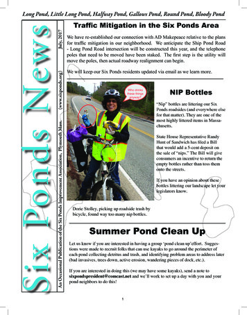
4.2 Wet Pond BMP Summary Fact SheetDescription: Constructed storm water wet ponds have apermanent pool, a temporary pool and typically a littoral shelfwith planted vegetation. Runoff from each rain event isdetained and pollutants are treated in the pond. Temporarystorage (live storage) is provided above the permanent poolelevation and is released at a controlled rate.Pollutantremoval is primarily accomplished through sedimentation andbiological processing.STORMWATER MANAGEMENTSUITABILITYIMPORTANT CONSIDERATIONSDESIGN CRITERIA: Minimum contributing drainage area of 25 acres, unless a waterbalance computation is performed that shows the pond does notgo more than one foot below permanent pool lelevation.A sediment forebay must be provided.Inflow energy dispersion structure is required to distribute flowand prevent short-circuiting and resuspension.Maximum average depth of permanent pool not to exceed 9feet. Minimum average permanent pool depth must be 3 feet.Side slopes to the basin must not exceed 3:1 (h:v).Ten foot littoral shelves (safety ledges) must be provided andwetland plants should be incorporated.A landscaping/vegetation and maintenance plan is required.Minimum length to width ratio of 1.5:1.ADVANTAGES/BENEFITS: Moderate to high removal rate of urban pollutants.High general and technical community acceptance.Opportunity for wildlife habitat.Can have aesthetic value within developments.Extensive experience in using these facilities.L LowM ModerateH HighH1-inch, 6-hr Water Quality (WQv) ControlH1-yr, 24-hr Channel Protection (CPv) ControlHPeak Attenuation Control for 10-yr, 6-hr StormHPeak Attenuation Control for 25-yr, 6-hr stormWet detention basins facilities are highly effective in controllingpollution removal for the 1-inch, 6-hr storm (WQv) and can bedesigned to control the volume for the 1-yr, 24-hr storm (CPv)and peak attenuation for the 10- and 25-yr, 6-hr storms.IMPLEMENTATION CONSIDERATIONSHLand RequirementsLCapital CostMMaintenance CostMClogging Issues with OrificesDISADVANTAGES/LIMITATIONS: Potential for thermal impacts/downstream warming.Dam height design requirements for high relief areas.Basin drainage can be problematic for low relief terrain.Can increase downstream drainage and flooding problems if notproperly designed and sited.In soils with high permeability, infiltration devices should beconsidered instead of wet pondsOutlet orifice clogging may be a problemWill require maintenance to preserve the aesthetic value.Permanent pool elevation should be no higher than 6” abovethe seasonally high water table (SHWT).MAINTENANCE CONSIDERATIONS: Inspect outlet facilities for damage and clogging.Detention basins must be cleaned out after 25 percent of themain pond storage capacity is lost and forebays cleaned outafter 50 percent of forebay capacity is lost.Adequate access must be provided and maintained forinspection and maintenance.General trash removal.PRIMARY POLLUTANT REMOVAL PROCESSES SettlingPOLLUTANT REMOVAL iencyStandardEfficiencyTSS-OnlyEfficiency4 days0.32 days0.64 days0.4PollutantRemovalRates85% TSS70% TP60% TSS40 % TP85% TSS
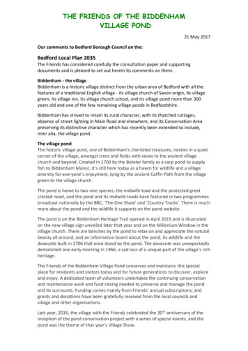
4.2Wet Ponds4.2.1General DescriptionWet ponds (also referred to as retention basins, storm water ponds, or wet extended detention basins)are constructed storm water basins that have a permanent (dead storage) pool of water throughout theyear and a temporary storage pool that fills during storm events. They can be created by excavating analready existing natural depression or through the construction of embankments.Runoff from each rain event is detained by either displacing the permanent pool or by temporarily fillingthe temporary pool. Pollutant removal occurs in the permanent and temporary pool through gravitationalsettling and potentially through biological uptake by the vegetation and plants that surround thepermanent pool on the littoral shelf. The permanent pool also serves to protect deposited sediments fromre-suspension. The upper stages of a storm water detention basin are designed to provide extendeddetention of the water quality control volume (WQv), channel protection control volume, 1-year, 24 hourstorm (CPv), as well as normal detention of larger storm events to meet Qp requirements.Wet ponds are among the most cost-effective and widely used storm water practices. A well-designedand landscaped wet pond can be an aesthetic feature on a development site when planned and locatedproperly. In some cases, wet ponds may be used for irrigation.For design purpose in this manual, a wet pond is where 100% of the water quality volume is stored in theextended detention (ED) storage (temporary pool) provided above the permanent pool. During stormevents, water is detained above the permanent pool and released over 2 to 4 days, depending on thepollutant removal goals of the designer. In addition, the permanent pool volume must be several timesgreater than the temporary pool volume, also depending on the pollutant removal goals of the designer.Multiple wet ponds systems consist of constructed facilities that provide water quality and quantity volumestorage in two or more cells. The additional cells can create longer pollutant removal pathways. Thebenefits of the additional cells can be designed through an assessment of the additional detention timethat is provided. Figure 4.2.1 shows a typical local wet pond and Figure 4.2.2 show a schematic of astandard wet pond design.Figure 4.2.1 Wet Pond ExampleCharlotte-Mecklenburg BMP Design ManualJuly 1, 20134.2.1
Figure 4.2.2 Wet Pond Schematic4.2.2Storm Water Management SuitabilityWet ponds can be designed to control both storm water quantity and quality. Thus, a wet pond can beused to address all of the design storms of interest.Water QualityWet ponds treat incoming storm water runoff by physical, biological, and chemical processes. Theprimary removal mechanism is gravitational settling of particulates, metals, and organics as storm waterrunoff resides in the basin. Another potential mechanism for pollutant removal is uptake by wetlandplants on the littoral shelf in the permanent pool – particularly of nutrients. Volatilization and chemicalactivity also work to break down and eliminate a number of other storm water contaminants such ashydrocarbons. Permanent pool elevation should be no higher than 6” above the seasonally high watertable (SHWT).Charlotte-Mecklenburg BMP Design ManualJuly 1, 20134.2.2
Channel ProtectionA portion of the storage volume above the permanent pool in a wet pond can be used to provide for thechannel protection volume (CPv). This is accomplished by releasing the 1-year, 24-hour storm runoff over24 hours (a minimum of 5 percent of the CPv must remain within the wetland temporary storage volumeth24 hours after the 12 hour, the center of rainfall for projects within Mecklenburg County and the sixTowns. Within the City of Charlotte and its ETJ, this release is over 48 hours.On-Site Flood ControlA wet pond can attenuate the post-development peak flow of the 10- and 25-year, 6-hour storm (ifrequired) (Qp) to pre-development levels by using the water quality and channel protection storagevolume and/or using additional storage volume above the water quality and channel protection volume.The wet pond emergency spillway design is the 50-year storm with 6 inches of freeboard for ponds lessthan 15 feet in height. More detailed design standards for embankments taller than 15 feet can be foundin the North Carolina Dam Safety Regulations.4.2.3Pollutant Removal CapabilitiesThree wet pond designs have been developed for application in the Mecklenburg County area. Theoptimal efficiency design has the capability to remove 85% of the total suspended solids and 70% of thetotal phosphorus load. The standard efficiency design has the capability to remove 60% of the totalsuspended solids and 40% of the total phosphorus load. The TSS-only efficiency design has thecapability to remove 85% of the total suspended solids and negligible total phosphorus load. All of thesedesigns assume urban post-development runoff conditions that has been observed in the MecklenburgCounty area and that the facilities are sized, designed, constructed and maintained in accordance withthe recommended specifications contained in this manual. The design pollutant removal rates are derivedfrom sampling data and computations completed for the development of this manual. In a situation wherea removal rate is not deemed sufficient, additional controls may be put in place at the given site in aseries or “treatment train” approach. Pollution removal rates are affected by the choice of designvariables. See Section 4.2.4 for a discussion of design variables and appropriate pollution removal ratesfor specific designs.4.2.4Planning and Design CriteriaThe following criteria are to be considered minimum standards for the design of a wet pond. Items listedin Section 4.1.4.A through 4.1.4.H. are requirements and must be addressed in the design. Items listed inSection 4.1.4.I. are recommendations and are optional.A.Design RequirementsFollowing is a list of design requirements that must be followed in the design of wet pond facilities. Following are the design values that are required for the three wet pond facility designs that areavailable for application in Mecklenburg County. The appropriate minimum design values andassociated pollutant removal rates for each of the three designs are given in Table 4.2.1.Charlotte-Mecklenburg BMP Design ManualJuly 1, 20134.2.3
Table 4.2.1 Design Values and Pollution Removal RatesThresholdMin. WQvDetention TimeWQv/PPv RatioOptimal Efficiency4 days0.3Standard Efficiency2 days0.6TSS-Only Efficiency4 days0.4Pollution Removal Rate85% TSS70% TP60% TSS40% TP85% TSS Water quality treatment volume (WQv) should be between 30% and 60% of the permanent poolvolume, depending on the pollutant removal goals of the BMP. A portion of the WQv may be used forirrigation, which may be approved on a site-by-site basis. Five percent of the water quality treatment volume (WQv) must remain within the wet pond temporarystorage volume for a duration between 2 and 4 days beyond the center of the storm event (center ofthe 1-inch, 6-hour storm event is assumed to be 3 hours), depending on the pollutant removal goalsof the BMP. The routing of the channel protection volume (CPv) is to be designed per this manual. Designs thataccount for a 4-day detention time for the WQv, but which release the additional volume of the CPv ina manner that does not meet the intent of the slow release rate of the additional volume are notacceptable. A wet pond must have a minimum contributing drainage area of 25 acres or more to maintain apermanent pool unless water balance calculations are performed for wet ponds that receive runofffrom drainage areas less than 25 acres. The water balance computations must show that the pondwill maintain a water level no lower than 1 foot below the permanent pool elevation. Permanent pool elevation should be no higher than 6” above the seasonally high water table (SHWT).It is expected that a sufficient analysis will have the following minimum elements: (1) multiple soilsamples serving to identify the soil type, (2) multiple field K results, (3) multiple soil samples toestablish the SHWT at the proposed pond location, (4) a clear statement of the conservative aspectsof the design case subjected to the hydrogeological analysis. An anti-clogging device must be provided for the wet pond outlet. Refer to Chapter 5 for moreinformation. A sediment forebay must be provided to allow heavier sediments to drop out of suspension before therunoff enters the permanent pool. All forebays must be sized to hold a volume equal to 0.2 inchesper impervious acre of contributing watershed. Inflow energy dispersion control structure is required to distribute flow and prevent short-circuiting andre-suspension of pollutants. This is normally accomplished by including a rip-rap apron at the forebayinlet. The pipe invert at the flared end section or endwall should be at the permanent pool, notsubmerged. Wet pond main pond areas must be cleaned out after 25 percent of the storage capacity is lost andforebays cleaned out after 50 percent of storage capacity is lost. The designer must convert thesestorage volume thresholds to site-specific depth thresholds that can be easily measured in the field.Charlotte-Mecklenburg BMP Design ManualJuly 1, 20134.2.4
To avoid stratification and anoxic conditions, maximum average depth of the permanent pool shouldnot exceed 9 feet. However, deeper depths near the outlet will yield cooler bottom water dischargesthat may mitigate downstream thermal effects. Minimum average depth for the wet pond must be 3 feet. Side slopes to the wet pond must not be steeper than 3:1 (h:v) without safety precautions. If mowingis anticipated, the side slopes should terminate on a safety bench. The safety bench requirementsmay be waived if slopes are 4:1 or gentler. See Figure 4.2.3. Littoral shelves (aquatic shelf) must be provided around the main permanent pond perimeter asminimum safety benches and to potentially increase biological uptake through recommended shallowwater plantings. The minimum width of the littoral shelf is 10 feet with a slope of 10:1 (horizontal :vertical). Half of the shelf should be submerged below the permanent pool, while the other five feetshould be above water. Appropriate plantings should be provided on the littoral shelf, but alternatevegetation plans may be submitted for review. Alternative vegetation plans may include floatingislands and bank stabilization of wet ponds used for irrigation. A landscaping/vegetation and maintenance plan is required. The minimum length to width ratio of 1.5:1 is required. Wet ponds cannot be located within a stream or any other navigable waters of the U.S., includingwetlands, without obtaining a Section 404 permit under the Clean Water Act, and any other applicableState and/or Federal Permits. In no case should a building be located within the impoundment area of the storm water facility All embankments shall be designed per the North Carolina Dam Safety Law of 1967, if applicable,and designed according to the requirements in Section 4.0.6. of this manual. No utilities (sewer lines, power lines, water lines, etc.) shall be located within or under the storm waterfacility Minimum setback requirements for wet pond facilities (when not specified by other ordinance orcriteria): From a property line – 10 feet From a private well – 100 feet; if well is down gradient from a hotspot land use then the minimumsetback is 250 feet. From a septic system tank/leach field/spray area – 50 feet A water-tight seal (rubber boot or equivalent) must be provided between all riser and pipe jointconnections to minimize leakage. Outlet structures should have protected access that may be accessed easily from the shore forinspection. Boats and ladders should not be needed to access outlet structures.B.Physical Specifications/GeometryIn general, wet pond designs are unique for each site and application. However, there are a number ofgeometric ratios and limiting depths for wet pond design that must be observed for adequate pollutantremoval, ease of maintenance, and improved safety.Charlotte-Mecklenburg BMP Design ManualJuly 1, 20134.2.5
Proper geometric design is essential to prevent hydraulic short-circuiting, which results in the failureof the wet pond to achieve adequate levels of pollutant removal. The minimum length-to-width ratiofor the permanent pool shape is 1.5:1, and should ideally be greater than 3:1 to avoid short-circuiting.In addition, wet ponds should be wedge-shaped when possible so that flow enters the permanent andtemporary storage area and gradually spreads out, improving the sedimentation process. Baffles,wet pond shaping or islands must be added within the permanent pool to increase the flow path, if theminimum length-to-width ratios are not met. The addition of baffles, wet pond shaping or islandsmust be assessed to ensure that the permanent pool and/or temporary pool design requirements aremet. The perimeter of all deep pool areas (4 feet or greater in depth) should be surrounded by the aquaticbench (littoral shelf). A littoral shelf (aquatic bench) extends inward from the normal pool edge (5feet) and has a maximum depth of 6 inches below the normal pool water surface elevation (seeFigure 4.2.3). When floating islands are used, the planted area should be between 8 and 10% of thetotal surface are of the wet pond. The contours and shape of the permanent pool should be irregular to provide a more naturallandscaping effect.Charlotte-Mecklenburg BMP Design ManualJuly 1, 20134.2.6
Figure 4.2.3 Typical Wet Pond Side Slope GeometryC.Pretreatment/InletsEach wet pond must have a sediment forebay at each concentrated flow location. A sediment forebay isdesigned to remove incoming sediment from the storm water flow prior to dispersal in a larger permanentpool. For each major inflow location, the forebay is a separate cell, formed by a barrier to control flow intothe main basin.The forebay is sized to contain 0.2 inches per impervious acre of contributing drainage and should be 4 to6 feet deep. The pretreatment storage volume is part of the total WQv requirement and may be includedin WQv for permanent pool sizing.A fixed vertical sediment depth marker must be installed in the forebay to measure sediment depositionover time. The bottom of the forebay may be hardened (e.g., using concrete, paver blocks, etc.) to makesediment removal easier. Information for clean-out depth for forebay should be included on maintenancesign.Charlotte-Mecklenburg BMP Design ManualJuly 1, 20134.2.7
Inflow channels are to be stabilized with flared riprap aprons or an equivalent energy dissipation device.Inlet pipes to the wet detention basin cannot be partially submerged. Inflow pipe, channel velocities, andexit velocities from the forebay must be non-erosive.Forebay berms constructed in fill should have the same compactions and soil standards as the main pondberm. The forebay berm must be constructed to the elevation of the Water Quality Event (WQv). A weiris then recommended that is a minimum of five feet wide (or 1/3 the length of the forebay berm,whichever is larger) and located to maximize the flow path of the runoff from the water quality storm. Theweir should be lined with NCDOT Class ‘B’ riprap and underlain with an appropriate filter fabric. The topsurface of the riprap is recommended to be located at the normal pool of the pond.D.Outlet StructuresFlow control from a wet pond is typically accomplished with the use of a concrete or aluminized steel riserand barrel. The riser is a vertical pipe or inlet structure that is attached to the bottom of the wet pond witha watertight connection. The outlet barrel is a horizontal pipe attached to the riser that conveys flowunder the embankment (see Figure 4.2.4).Figure 4.2.4 Typical Wet Pond Outlet StructureCharlotte-Mecklenburg BMP Design ManualJuly 1, 20134.2.8
A number of outlets at varying depths in the riser provide internal flow control for routing of the waterquality, channel protection volume control, and on-site flood control runoff volumes. The number oforifices can vary and is a function of the wet pond design.For the wet pond there is a need for an orifice (usually) that is sized to pass the water quality volume(WQv) that is temporarily stored on top of the permanent pool. Flow will first pass through this orifice,which is sized to release the water quality volume (WQv) in 2 – 4 days, depending on the pollutantremoval goals of the BMP design. The preferred design is a reverse slope pipe attached to the riser, withits inlet submerged 1 foot below the elevation of the permanent pool to prevent floatables from cloggingthe pipe and to avoid discharging warmer water from the surface of the wet detention basin. The nextoutlet is sized for the release of the channel protection storage volume (CPv). The outlet (often an orifice)invert is located at or above the peak stage associated with the water quality volume (WQv) and is sizedto release the channel protection storage volume (CPv) over a 24-hour period within Mecklenburg Countyand the six Towns and over a 48-hour period in Charlotte and its ETJ.Alternative hydraulic control methods to an orifice can be used and include the use of a broad-crestedrectangular weir, V-notch weir, proportional weir, or an outlet pipe protected by a hood that extends atleast 12 inches below the normal pool. Other approved non-clogging outlet designs are presented inChapter 5.Higher flows pass through openings or slots further up on the riser.After entering the riser, flow is conveyed through the barrel and is discharged downstream. Anti-seepcollars must be installed on the outlet barrel to reduce the potential for pipe failure.Riprap, or other energy dissipators must be placed at the outlet of the barrel to prevent scouring anderosion. If a wet pond outlet daylights to a channel with dry weather flow, care should be taken tominimize tree clearing along the downstream channel, and to reestablish a forested riparian zone in theshortest possible distance. See Chapter 8, Energy Dissipation, in the Charlotte-Mecklenburg StormWater Design Manual for more guidance.Each wet pond must have a bottom drain pipe with an adjustable valve that can drain the permanent poolwithin 24 hours. The bottom drain valve must be accessible by maintenance personnel during the 50-yearstorm event by either being located within the embankment or through alternative maintenance access.Some jurisdictions may allow the option of mechanical pumping of ponds for maintenance in lieu ofproviding a bottom drain. This option may not be allowed for BMPs that will be maintained by thejurisdiction.The wet pond bottom drain should be sized one pipe size greater than the calculated design diameter. Itis recommended that the drain valve be a plug valve conforming to AWWA C-504 Section 5.5 andoperable from a land-accessible location via a handwheel.The outlet system must be designed to be water-tight. A water-tight seal (rubber boot or equivalent) mustbe provided between all riser and pipe joint connections to minimize leakage. This is particularly crucialin the connection between the riser and barrel of the spillway.E.Emergency SpillwayAn emergency spillway must be included in the wet pond design to safely pass the 50-year storm event(or higher storm events, if applicable). The spillway prevents wet pond peak stages from overtopping theembankment and causing structural damage. The emergency spillway must be located so thatdownstream structures will not be impacted by spillway discharges.A minimum of 0.5 feet of freeboard must be provided, measured from the peak stage for the 50-yearstorm event to the lowest point of the dam embankment.Charlotte-Mecklenburg BMP Design ManualJuly 1, 20134.2.9
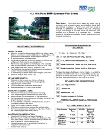
F.Maintenance AccessA maintenance right of way or easement must be provided to a wet pond from a public road or easement.Maintenance access should be at least 12 feet wide, maximum longitudinal slope of 15 percent, andmaximum cross slope of 5 percent, and be stabilized to support maintenance vehicles. A 20-foot widemaintenance access easement must be provided to ensure that the access remains in place.The maintenance access must extend to the forebay, safety bench, riser, and outlet and, to the extentfeasible, allow vehicles to turn around.Access to the inside of the riser must be provided by manhole covers, and manhole steps should bewithin easy reach of valves and other controls. Outlet structures should have protected access that maybe accessed easily from the shore for inspection. Boats and ladders should not be needed to accessoutlet structures.G.Safety FeaturesFencing of wet detention basins is not generally desirable, but may be allowed depending upon thejurisdiction. If a fence is included in the design, access must be provided for inspections. A preferredmethod to increase the safety features is to manage the contours of the wet detention basin through theinclusion of a safety bench (see Figure 4.2.3) to eliminate dropoffs and reduce the potential for drowning.In addition, the safety bench may be landscaped to deter access to the permanent pool.The outlet structure openings should not permit access by people not providing maintenance to thefacility. Warning signs should be posted near the wet pond to prohibit swimming and fishing in the facility.H.LandscapingAquatic vegetation plays an important role in pollutant removal in a wet pond. In addition, vegetation canenhance the appearance of the wet pond, stabilize side slopes, serve as wildlife habitat, and cantemporarily conceal unsightly trash and debris. Therefore, wetland plants should be used in a wet ponddesign, along the aquatic bench (fringe wetlands), the safety bench and side slopes, and within shallowareas of the permanent pool itself. The best elevations for establishing wetland plants, either throughtransplantation or volunteer colonization, are within 6 inches (plus or minus) of the normal pool elevation.For planting within wet ponds, it is necessary to determine what hydrologic zones will be created.Hydrologic planting zones describe the degree to which an area is inundated by water. The hydrologicplanting zones are illustrates for a typical wet pond in Figure 4.2.5. Plants have differing tolerances toinundation and the six zones described in this section will dictate which plants will survive where.Chapter 6 of this manual provides detailed description of zones. In Zone 1 plant material must be able to withstand constant inundation of water of one foot to amaximum of three feet in depth. In Zone 2 plant material must be able to withstand constant inundation of water to depthsbetween six inches and one foot deep. In Zone 3 plant material must be able to withstand frequent inundation with water, as well asoccasional drought. In Zone 3 plant will be partially submerged at certain times. In Zone 3 plant should be located to reduce human access where there are potential hazards, butshould not block the maintenance access. In Zone 3 plant should be resistant to disease and other problems which require chemicalapplications (since chemical application is not advised in storm water ponds). Native plants arepreferred because they are low maintenance and disease resistant. In Zone 3, where shoreline plants will be susceptible to being smothered by floating trash,provisions for routine maintenance, including removal of trash and other wrack, should be a partCharlotte-Mecklenburg BMP Design ManualJuly 1, 20134.2.10
of the maintenance plan.If shading is needed along the shoreline, the more rapidly-growing species such as Sycamore arepreferred over the more slowly developing species, such as Swamp White Oak. For this purpose,trees should not be planted in Zone 3, but rather in the adjacent Zone 4.In Zone 3 and 4 plants material should have very low maintenance requirements, since they maybe difficult to access.In Zone 4 plants must be able to withstand periodic inundation of water after storms, as well asoccasional drought during the warm summer months.In Zone 4 plants should stabilize the ground from erosion caused by run-off.In Zone 5 plant material should be able to withstand occasional but brief inundation duringstorms. In between storms, typical moisture conditions may be moist, slightly wet, or even exhibitdrought conditions during the dry weather periods.In Zone 5 plants should stabilize the basin slopes from erosion.Ground cover in zone 5 and 6 should be very low maintenance, since they may be difficult toaccess on steep slopes or if frequency of mowing is limited.In Zone 6 plant material should be able to withstand occasional but brief inundation duringstorms. In between storms, typical moisture conditions may be moist to slightly wet, with thepotential for drought like conditions during extended dry weather periods.In Zone 6 plants should be used to stabilize the basin slopes from erosion.Charlotte-Mecklenburg BMP Design ManualJuly 1, 20134.2.11
Figure 4.2.5Wet pond Planting ZonesWoody vegetation must not be planted on the embankment or allowed to grow within 15 feet of the toe ofthe embankment and 25 feet from the principal spillway structure.No buildings should be located within 25 feet of the maximum water surface elevation.Charlotte-Mecklenburg BMP Design ManualJuly 1, 20134.2.12
Existing trees must be preserved in the buffer area during construction. It is desirable to locate forestconservation areas adjacent to wet ponds. To discourage resident geese populations or otherdetrimental wildlife, the buffer can be planted with trees, shrubs and native ground covers.The soils of a wet pond buffer are often severely compacted during the construction process to ensurestability. The density of these compacted soils is so great that it effectively prevents root penetration andtherefore may lead to premature vegetation mortality or loss of vigor. Consequently, it is advisable toexcavate large and deep holes around the proposed planting sites and backfill these with uncompactedtopsoil.Other Landscaping considerations include the following:I. Plants should be used to stabilize the bottom of the pond, as well as the edge of the pond,absorbing wave impacts and reducing erosion, when water level fluctuates. Plants should be used to stabilize the shoreline to minimize erosion caused by wave and windaction or water fluctuation. Plant material should, whenever possible, shade the water surface, especially the southernexposure. Plants should be used to shade the low flow channel to reduce pool warming whenever possible. Plants should be used to reduce pedestrian access to the deeper pools as a natural barrier
Charlotte-Mecklenburg BMP Design Manual July 1, 2013 4.2.1 4.2 Wet Ponds . 4.2.1 General Description . Wet ponds (also referred to as retention basins, storm water ponds, or wet extended detention basins) are constructed storm water basins that have a permanent (dead storage) pool of water throughout the