Transcription
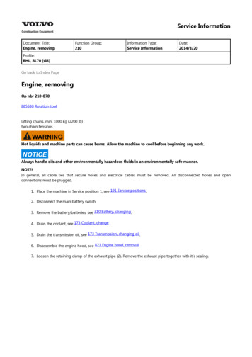
Service InformationDocument Title:Engine, removingFunction Group:210Information Type:Service InformationDate:2014/3/20Profile:BHL, BL70 [GB]Go back to Index PageEngine, removingOp nbr 210-070885530 Rotation toolLifting chains, min. 1000 kg (2200 lb)two chain tensionsWARNINGHot liquids and machine parts can cause burns. Allow the machine to cool before beginning any work.NOTICEAlways handle oils and other environmentally hazardous fluids in an environmentally safe manner.NOTE!In general, all cable ties that secure hoses and electrical cables must be removed. All disconnected hoses and openconnections must be plugged.1. Place the machine in Service position 1, see 191 Service positions.2. Disconnect the main battery switch.3. Remove the battery/batteries, see 310 Battery, changing.4. Drain the coolant, see 173 Coolant, change.5. Drain the transmission oil, see 173 Transmission, changing oil.6. Disassemble the engine hood, see 821 Engine hood, removal.7. Loosen the retaining clamp of the exhaust pipe (2). Remove the exhaust pipe together with it s sealing.
Figure 1exhaust assembly, disassembly1.2.3.retaining screws filler neck assemblyexhaust pipe with retaining clampretaining screws exhaust assembly bracket8. Loosen and remove the retaining screws (1) of the oil filler neck assembly.9. Loosen the retaining screws and disconnect the flexible exhaust tube from the turbocharger.10.WARNINGThe parts are heavy. Take appropriate safety cautions when handling them.Use a slop to attach the exhaust assembly to a suitable lifting device.11. Loosen and remove the retaining screws (3) of the exhaust assembly bracket.12. Remove the exhaust assembly from the machine.13. Loosen the retaining clamps (4, 5) from the upper radiator hose (1) and remove the hose.
Figure 2radiator hose and air inlet, disassembly1.2.3.4.5.upper radiator hoseair inletretaining clampretaining clampretaining clamp14. Loosen the retaining clamp (3) from the air inlet (2) and remove it from the air filter assembly.15. Loosen and remove the hoses (4, 5) connecting the expansion tank (3) with the coolant pump (6).NOTE!Loosen the retaining clamps on the pump side, so the hoses can be removed with the tank.Figure 3radiator with attached parts1.2.radiatorhose
3.4.5.6.expansion tankhosehosecoolant pump16. Loosen and remove the hose (2) connecting the expansion tank (3) to the radiator (1).NOTE!Loosen the retaining clamp on the radiator side, so the hose can be removed with the tank.17. Loosen the retaining screws connecting the expansion tank s attachment bracket to the machine frame.18. Remove the expansion tank with the attachment bracket.19. Disconnect the two pressure sensor connectors from the air filter (2).Figure 4air filter, disassembly1.2.3.4.attachment bracketair filterhoseturbocharger20. Loosen the retaining clamp connecting the air filter hose (3) to the turbocharger (4).21. Remove the hose from the turbocharger.22. Loosen and remove the retaining screws connecting the air filter to the engine (4 pcs).23. Remove the complete air filter assembly.24. Loosen and remove the retaining screws of the fan guard.Figure 5fan, disassembly
1.2.3.4.fanfan adapterV-belt pulleyretaining screws25. Remove the fan guard.26. Loosen and remove the retaining screws (4) of the fan (1).27. Slightly turn the fan, to remove it from the fan adapter (2).NOTE!Leave the fan inside the fan shroud.28. Loosen and remove the retaining screws (4) together with the fan adapter.29. Loosen and remove the retaining screws of the fan shroud.30. Remove the fan shroud together with the fan.31. Disassemble the transmission oil filler pipe from the engine.32. Remove the coolant pump (1) connection of the lower coolant hose (2).Figure 6coolant hose, disassembly1.2.coolant pumplower coolant hose33. Remove the two battery connection cables from the starter motor.34. Remove all electrical connectors and cables from the engine. Make notes to which component the connectors andcables have to be attached.35. Loosen the hose (1) from the engine oil cooler.
Figure 7hoses, disassembly1.2.hose to engine oil coolerhose to coolant pump36. Loosen the hose (2) from the coolant pump.37. Loosen and remove the hose (1) from the main fuel filter (3).Figure 8main fuel filter, disassembly1.2.3.hose (tank connection)attachment bracketfuel filter38. Loosen and remove the fuel filter from the attachment bracket (2). Fasten the filter to the engine (cable tie).39. Loosen and remove the filter's attachment bracket from the machine.40. Loosen the adjusting nuts (1) of the throttle cable.
Figure 9throttle cable, disassembly1.adjusting nuts41. Loosen and remove the retaining nut. Remove the throttle cable from the lever (1).Figure 10throttle cable, disassembly1.accelerator lever42. Secure all disconnected hoses and cables, so they can t be catched when removing the engine.43. Remove the plate on the engine to access the screws connecting engine to turbocharger.
Figure 11engine, retaining screws torque converter1.2.3.engineretaining screws, torque convertertransmission44. Loosen the connection screws from engine to torque converter (4 pcs). To turn the engine and screws in the rightposition, use special tool.Special tool:885530 Rotation toolWARNING45.The parts are heavy. Take appropriate safety precautions.Place a suitable support under transmission and hydraulic pump to avoid overturning when engine is disconnected.46. Attach the engine with a suitable chain and two chain tensions to a crane. The chain tensions are used to align theengine while removing from machine.Figure 12engine, attached to lifting device1.Additional lifting eye must be attached for the 2nd chain tensionEngine weight (dry):520 kg (1146.2 lb)47. Loosen the connection screws from engine to transmission.48. Loosen the connection screws from the engine to the engine mounts (3) (on the left and right of the machinefront).
Figure 13engine mounts, disassembly1.2.3.spacerspacerengine mounting49. Disassemble the engine mounts from the frame.NOTE!Take care not to loose the spacers.50.WARNINGRisk of crushing injuriesUse the crane and the chain tensions to remove the engine from the transmission shaft.51.WARNINGHeavy lift. Make sure that everybody stands well back from the engine when it is lifted.Carefully lift the engine out of the machine and place the engine on suitable stable surface.NOTE!Take care not to catch any hoses or cables when removing.
Service InformationDocument Title:Engine, installationFunction Group:210Information Type:Service InformationDate:2014/3/20Profile:BHL, BL70 [GB]Go back to Index PageEngine, installationOp nbr 21072-114360000 Vacuum pumpLifting chains, min 1000 kg (220 lb)NOTE!In general, all strip clamps that have been removed must be replaced.1. Install the gearbox, see Gearbox, installation in Section 4.2. Transfer the bracket to the engine.3. Transfer the hose connections.Transfer the electrical cables.Transfer the front right and left engine mounting.Tightening torque:140 15 Nm (103 11 lbf ft)4. Connect a lifting chain between the lifting eyes and to a lifting device.Carefully lift and balance the engine-gearbox unit when the unit is lifted into the machine.Figure 11.2.Lifting eyeLifting eye5. Remove the rubber cushion from the mounting bracket for the gearbox, and lower the gearbox onto the mountingbracket.Place a jack under the gearbox and lift it up and install the rubber cushion and the washer on the mountingbracket. Lower the gearbox and install the attaching screws 1 on both sides.Tightening torque: 173 15 Nm (127 11 lbf ft)
Figure 21.Screw6. Install the attaching screws for the engine.Tightening torque: 173 15 Nm (127 11 lbf ft)Figure 31.2.Attaching screwAttaching screw7. Apply some grease to the o-ring and place it on the working pump.Move the working pump carefully into the gearbox.Remove the strap and the pinchbar.Figure 4
1.2.StrapPinchbar8. Install the screws (2 screws) gearbox unit–working pump.Figure 51.Screw9. Connect the connector to the work pump.Figure 61.Connector10. Connect the ground cables to the gearbox.
Figure 71.2.Ground cableGround cable11. Connect the hose to the gearbox.Figure 81.Hose12. Connect the hoses to the gearbox.Figure 9
1.2.3.HoseHoseHose (hidden)13. Connect the hoses to the gearbox.Figure 101.2.HoseHose14. Install the shift lever.Figure 111.Shift lever15. Install the plate.
Figure 121.Plate16. Place rubber mat on the floor and install the seat.Figure 131.2.SeatRubber mat17. Connect the rear propeller shaft 1 to the gearbox.Tightening torque: 31–41 Nm (23–30 lbf ft)Figure 141.Propeller shaft18. Connect the front propeller shaft 1 to the gearbox unit.Tightening torque: 31–41 Nm (23–30 lbf ft)
Figure 151.Propeller shaft19. Connect the electrical cables to the starter motor.Figure 161.Electrical cable20. Install the throttle control cable and tighten the nuts.Figure 171.Nut21. Connect the fuel filter to the hydraulic tank.Connect the fuel hoses to the fuel filter.
22. Connect the hoses (2 hoses, one hidden) to the engine and fit the fuel filter/pump on the hydraulic tank.Figure 181.Hoses23. Connect the hose to the engine.Figure 191.Hose24. Install the bracket with the screws (3 pcs). Install the air cleaner with the screws. Tighten the hose clamp.Figure 201.Screws
Thank you very much foryour reading. Please ClickHere. Then Get COMPLETEMANUAL. NO WAITINGNOTE:If there is no response toclick on the link above,please download the PDFdocument first and thenclick on it.
2.3.4.Hose clampScrewsAir cleaner25. Install the silencer and the nuts for the turbocharger.Install the attaching screws (4 attaching screws, 2 underneath).Figure 211.2.Attaching screwsNuts26. Install the fan.Figure 221.Fan27. Install the radiator casing and the fan guard.Figure 23
1.2.Fan guardRadiator casting28. Lift in the hydraulic oil cooler/radiator and install the screws on both sides.Figure 241.Screw29. Install the screws radiator and radiator casing (4 screws). Connect the radiator hoses and the lower hose (hidden).Figure 251.2.3.4.5.HoseHoseHoseHoseScrews30. Connect the ground cable and turn on the electric power with the battery disconnect switch.
Figure 261.2.Battery disconnect switchGround cable31. Connect the vacuum pump, see Vacuum pump, connection in section 9.32. Lock the hydraulic oil cooler with the locking device. Connect the hoses (4 hoses) to the hydraulic oil cooler.Figure 271.2.Locking deviceHoses33. Turn off the vacuum pump.34. Install the clamps on both sides on the cooler.
BHL, BL70 [GB] Go back to Index Page Engine, removing Op nbr210-070 885530Rotation tool Lifting chains, min. 1000 kg (2200 lb) two chain tensions WARNING Hot liquids and machine parts can cause burns. Allow the machine to cool before beginning any work. NOTICE Always handle oils and other environmentally hazardous fluids in an environmentally .