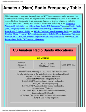
Transcription
Frequency Sensitive ModeENTSO-E guidance document for nationalimplementation for network codes on grid connection31 January 2018ENTSO-E AISBL Avenue de Cortenbergh 100 1000 Brussels Belgium Tel 32 2 741 09 50 Fax 32 2 741 09 51 info@entsoe.eu www. entsoe.eu
Frequency Sensitive ModeTable of ContentsDESCRIPTION .4Code(s) & Article(s) .4Introduction .4NC frame .4INTERDEPENDENCIES .4Between the CNCs .4In other NCs .5System characteristics .5Technology characteristics .13COLLABORATION .13TSO – TSO .13RSO – Grid User .13FiguresFigure 1 : Insensitivity or backlash representation .8Figure 2 : Frequency profile observed with an insensitivity modelled as an Active Dead-band (redcurve) .9Figure 3: Probability density function of frequency as a function of share of units with /- 10mhzinsensitivity .10Figure 4 : Frequency response with step deadband (orange), no-step deadband (grey) or withoutdeadband (blue) .11Figure 5 : Probability density function of frequency as a function of share of units with /- 10mhzdeadband.122ENTSO-E AISBL Avenue de Cortenbergh 100 1000 Brussels Belgium Tel 32 2 741 09 50 Fax 32 2 741 09 51 info@entsoe.eu www. entsoe.eu
Frequency Sensitive Mode3ENTSO-E AISBL Avenue de Cortenbergh 100 1000 Brussels Belgium Tel 32 2 741 09 50 Fax 32 2 741 09 51 info@entsoe.eu www. entsoe.eu
Frequency Sensitive ModeDESCRIPTIONCode(s) &Article(s)Introduction RfG, Article 15(2)(d) – Frequency Sensitive ModeRfG, Article 15(2)(e) – Frequency RestorationFrequency Sensitive Mode (or ‘FSM’) means the operating mode of a power-generatingmodule or HVDC system in which the active power output changes in response to achange in system frequency, in such a way that it assists with the recovery to targetfrequency.The objective of this guidance document is to help to determine the maincriteria/motivation for the specifications of the FSM capabilities of power generatingmodules at national level.For adequate specifications of the relevant parameters it is essential to be aware of theobjective of the FSM functions and to understand how it interacts with other frequencystability requirements.For each synchronous area, proposals for national choices for the non-exhaustive FSMparameters are provided through this IGD.NC frameThe non-exhaustive topics are those for which the European level CNCs do not containall the information or parameters necessary to apply the requirements immediately. Theserequirements are typically described in the CNC as “TSO / relevant system operator shalldefine” or “defined by / determined by / in coordination with the TSO / relevant TSO”.Despite choices need to be made at national level, frequency-related issues require asimilar response within the same synchronous area and therefore strict collaborationbetween TSOs of the same synchronous area is necessary.See also the general IGD on parameters related to frequency stability.Further infoIGD on parameters related to frequency stabilityIGD on frequency rangesIGD on limited frequency sensitive mode (LFSM-O/U)IGD on admissible power reduction at low frequenciesIGD on demand response system frequency control (DR SFC)INTERDEPENDENCIESBetween theCNCsFrequency variations require a coordinated response at synchronous area level and by allsystem users who provide frequency response.Therefore there must be a coordinated frequency response across the network extendingto not only the different interconnected countries horizontally, but also vertically acrossthe interconnected network within a country i.e. DSOs, CDSOs and the users themselves.Also there must be collaboration between all of these parties as we move typically from: an early response (i.e. FSM, DR SFC) even to small frequency variation to, a response (i.e. LFSM, DR SFC) to larger frequency variation, and;4ENTSO-E AISBL Avenue de Cortenbergh 100 1000 Brussels Belgium Tel 32 2 741 09 50 Fax 32 2 741 09 51 info@entsoe.eu www. entsoe.eu
Frequency Sensitive Mode In other NCsfinally a last response by low frequency demand disconnection (LFDD) to avoidnetwork collapseThe System Operation Guidelines1 (SOGL, Title 5 – esp. Article 154 and 156 and Title6) needs to be taken into account when defining the application of FSM and frequencyrestoration control capabilities in system operation.Implementation of RfG requirements at national level shall ensure that technicalcapabilities and, where applicable, initial settings of parameters are available to coveroperational needs defined through these operational guidelines.SystemA frequency deviation away from the nominal frequency results from an imbalancecharacteristics between generation and demand that occurs continuously during normal systemoperation or after an incident like a loss of generation. System frequency increases incase generation is higher than demand and decreases in case generation is lower thandemand.The objective of frequency containment is to maintain the balance between generation anddemand within a synchronous area. By the joint action of all interconnected parties/TSOs,it aims to stabilise the system frequency at a stationary value after such disturbance orincident in the time-frame of seconds. It depends on generation or load resources madeavailable to the TSOs, which are called frequency containment reserves (FCR) and are infact deployed by generators or demand units running in frequency sensitive mode (FSM).HVDC systems connecting different synchronous areas can also contribute to FCR.The objective of frequency restoration control is to restore system frequency to its nominalvalue and the power exchanges between control areas to their reference values. It isprovided by frequency restoration reserve (FRR), deployed by generators or demand unitswith frequency restoration capabilities.Within a synchronous area FCR and FRR are dimensioned to cover a reference imbalance.For example, the relevant design criteria for defining the FCR amount within theContinental Europe (CE) is a load imbalance of 3.000 MW. FCR shall be completelydeployed at a deviation of 200 mHz.According to NC RfG, FSM and frequency restoration capabilities could be provided bytype C and D power generating modules (PGM) and relevant non-exhaustive parameters(NC RfG Article 15.2.d) shall be defined at national level.1COMMISSION REGULATION (EU) 2017/1485 of 2 August 2017 establishing a guideline on electricitytransmission system operation5ENTSO-E AISBL Avenue de Cortenbergh 100 1000 Brussels Belgium Tel 32 2 741 09 50 Fax 32 2 741 09 51 info@entsoe.eu www. entsoe.eu
Frequency Sensitive ModeAccording to NC RfG Article 15.2.d, non-exhaustive FSM parameters to be defined atnational level are the following:Active power range P1 /PmaxBetween 1.5 – 10%DroopBetween 2-12%Frequency response insensitivity fi Between 10 – 30 mHz fi /fnBetween 0.02 – 0.06%Frequency response deadbandBetween 0 – 500 mHzMaximum initial delay of FSM activation SPGM : 2s (to be justified if 2s)(t1)PPM : to be specified by the relevant TSOMaximum delay of FSM full activation 30 s(t2)TABLE 1 : PARAMETERS FOR ACTIVE POWER RESPONSE IN FSMRfG requirements shall ensure, that technical capabilities and, where applicable, initialsettings of parameters are available to cover operational needs, such as FCR minimaltechnical requirements (SOGL Art 154).Regarding Active power range related to maximum capacity P1 / Pref and droop :This requirement is applicable to type C & D PGMs. There is a need to ensure that overallFCR is covered at synchronous area level (cf. synchronous area operational agreementsconcerning dimensioning of FCR, and SOGL Article 153). This shall not be understoodas setting the same parameters for each power generating module within a synchronousarea, but that each TSO defines those parameters in its control area to cover its requiredlevel of FCR.It is recommended that each TSO shall identify and quantify critical future scenarioswith low instantaneous penetration of C & D units and then defines the followingminimal requirements to cover its required level of FCR : P1 / Pmax value within the range to ensure that its FCR obligation will bemainly covered by C & D PGMs in its country (a power generating modulecould choose to do more than this minimal requirement). Droop should be calculated to be able to increase/decrease power from P1 / Pmax for FCR full activation at a defined frequency deviation, e.g. 200 mHzfor PGMs within the Continental Europe synchronous area. This is importantto calculate the droop to make sure the reserve ( P1 / Pmax) could be fullydeployed for the synchronous area reference frequency deviation (i.e 200mHz for CE, 500 mHz for GB)Compliance testing shall validate that this minimal requirement is met for a FCR fullactivation frequency deviation.Note : SOGL Art 156.6 states that a single power generation unit is not allowed to covermore than 5% of the FCR of a synchronous area.6ENTSO-E AISBL Avenue de Cortenbergh 100 1000 Brussels Belgium Tel 32 2 741 09 50 Fax 32 2 741 09 51 info@entsoe.eu www. entsoe.eu
Frequency Sensitive ModeAt operational timescales a PGM can provide a lower/higher volume of reserve (based onmarket needs) with an adjustable droop to achieve full activation at the defined frequencydeviation.According to NC RfG, the FSM droop is defined as𝑠[%] 100 𝑓 𝑃𝑟𝑒𝑓 𝑓𝑛 𝑃 Pref is the reference active power to which ΔΡ is related and may be specified differentlyfor synchronous power generating modules and power park modules. ΔΡ is the change inactive power output from the power-generating module. fn is the nominal frequency (50Hz) in the network, Δf is the frequency deviation in the network. At a change of frequency,the power generating module has to provide an active power output change according tothe droop.NC RfG allows for two options for defining Pref for power park modules, either Pmax or theactual active power output at the moment the FSM threshold is reached.Regarding activation of FSM:In the event of a frequency step response, the PGM controller should carefully manageovershoot and damping of the response aiming at avoiding unnecessary active poweroscillations.Regarding maximum admissible delay t1, Article 15(2)(d)(iv) shall be respected: “theinitial activation of active power frequency response required shall not be unduly delayed.If the delay in initial activation of active power frequency response is greater than twoseconds, the power- generating facility owner shall provide technical evidencedemonstrating why a longer time is needed. For power-generating modules withoutinertia, the relevant TSO may specify a shorter time than two seconds. If the powergenerating facility owner cannot meet this requirement they shall provide technicalevidence demonstrating why a longer time is needed for the initial activation of activepower frequency response”.It is proposed to use the widest possible technical capability of the power-generatingmodule.Regarding maximum full activation time t2, default value can be proposed refering tonormal operating conditions across a synchronous area. In case of forming local islandsaccidentally, a faster t2 could be requested by the TSO with the purpose of facilitating anappropriate system restoration. Therefore, the generator FSM control must be designedto allow a faster response in case of local needs, taking into consideration technologyspecifics.Initial delay t1Response activation(full activation) t2default value 2s for SPGM 500 ms for PPMCE, Nordic :30sGB10sIE/NI15sTABLE 2 : DELAYS FOR ACTIVATION OF ACTIVE POWER RESPONSE IN FSM7ENTSO-E AISBL Avenue de Cortenbergh 100 1000 Brussels Belgium Tel 32 2 741 09 50 Fax 32 2 741 09 51 info@entsoe.eu www. entsoe.eu
Frequency Sensitive ModeRegarding frequency response dead band and insensitivity:‘frequency response insensitivity’ means the inherent feature of the control systemspecified as the minimum magnitude of change in the frequency or input signal thatresults in a change of output power or output signal (NC RfG, art 2 (40).Originally, insensitivity or backlash is a lost motion in a mechanism caused by gapsbetween the parts (see figure below).FIGURE 1 : INSENSITIVITY OR BACKLASH REPRESENTATIONIt can be defined as “the maximum distance or angle through which any part of amechanical system may be moved in one direction without applying appreciable force ormotion to the next part in mechanical sequence”2, and is a mechanical form of deadband. Today, this concept is not totally applicable because power generation modulesare mainly connected through power electronics devices to the network. This process isequivalent to filter small variations of frequency and can be modelled as an active deadband which follows frequency values (see figure below);2Bagad, V.S. (2009). Mechatronics (4th revised ed.). Pune: Technical Publications.8ENTSO-E AISBL Avenue de Cortenbergh 100 1000 Brussels Belgium Tel 32 2 741 09 50 Fax 32 2 741 09 51 info@entsoe.eu www. entsoe.eu
Frequency Sensitive Modefrequency (Hz)time (s)FIGURE 2 : FREQUENCY PROFILE OBSERVED WITH AN INSENSITIVITY MODELLED AS AN ACTIVE DEAD-BAND (REDCURVE)Based on the network model of a unique generator connected to a load (self-regulationof the load assumed to be 1 %/Hz), different simulations have been performed assumingthat the percentage of power generating modules having an 10mHz-insensitivity variesfrom 0% to 100% to evaluate the impact of this parameter on frequency distribution. Animbalance (between supply and demand) profile is applied to the system. This profilecomes from real measurement of frequency (two days of September 2016) multiplied bythe minimum network power frequency characteristic of primary control for CEsynchronous area (15000 MW/Hz).9ENTSO-E AISBL Avenue de Cortenbergh 100 1000 Brussels Belgium Tel 32 2 741 09 50 Fax 32 2 741 09 51 info@entsoe.eu www. entsoe.eu
Frequency Sensitive ModePGM with insensitivity100% insensitivity80% insensitivity50% insensitivity20% insensitivity0% insensitivity0,03Probability ,0250,04f (Hz)50,06Figure 3: Probability density function of frequency as a function of share of units with /- 10mHz insensitivityInsensitivity allows power generating units not to react to small variations of frequency,but following the trend of frequency variation, thus there is a negligible impact on thefrequency distribution, even if a large number of power generating units are concerned.‘frequency response deadband’ centered at nominal frequency is adopted in governordesigns to reduce excessive controller activities and turbine mechanical wear for normalpower system frequency variations. Until the preset intentional deadband is reached, theturbine governor would not respond to system frequency excursion. In this paper, only theno-step-function implementation is considered because a step-function deadbandimplementation results in a step change in mechanical set-point and excessive stress onmechanical parts.10ENTSO-E AISBL Avenue de Cortenbergh 100 1000 Brussels Belgium Tel 32 2 741 09 50 Fax 32 2 741 09 51 info@entsoe.eu www. entsoe.eu
Frequency Sensitive ModeFIGURE 4 : FREQUENCY RESPONSE WITH STEP DEADBAND (ORANGE), NO-STEP DEADBAND (GREY) OR WITHOUTDEADBAND (BLUE)Based on the same modelling, different simulations have been performed assuming thatthe number of power generating modules having a 10mHz deadband varies from 0% to100% to evaluate the impact of this parameter on frequency distribution. An imbalance(between generation and demand) profile is applied to the system. This profile comesfrom real measurement of frequency (two days of September 2016) multiplied by theminimum network power frequency characteristic of primary control for CEsynchronous area (15000 MW/Hz).11ENTSO-E AISBL Avenue de Cortenbergh 100 1000 Brussels Belgium Tel 32 2 741 09 50 Fax 32 2 741 09 51 info@entsoe.eu www. entsoe.eu
Frequency Sensitive ModePGM with deadband (DB)0,03100% DB80% DB50% DB20% DB0% DBProbability density0,0250,020,0150,010,005049,94f (Hz)49,9649,985050,0250,0450,06FIGURE 5 : Probability density function of frequency as a function of share of units with /- 10mHz deadbandA deadband around nominal frequency results in power generating modules being lesssensitive to small frequency deviations centered around 50Hz. Modules with a deadbandaround nominal frequency do not perceive any frequency deviation within thisdeadband, and thus not change their active power output. As shown by the figure above,the number of power generating with a deadband should be limited to reduce the impacton the frequency distribution.Nota : In case of a large number of power generating modules with a deadband, somepower plants technologies could be impacted by mechanical constraints due to theaction of switching from one side to the other side of a deadband.Therefore, the number of power generating modules providing FCR with a deadbandaround nominal frequency shall be limited to not impair the objective of equal FCRprovision over frequency deviation. Notwithstanding this, a deadband around nominalfrequency may be used to deactivate FCR by setting it equal to the LFSM frequencythresholds.To ensure that frequency containment is provided by all TSOs through an equalityprinciple, it’s recommended to harmonize those two parameters at synchronous area level.In addition, RfG requirements should be consistent to FCR minimal technicalrequirements (SOGL Art 154): the maximum combined effect of inherent frequencyresponse insensitivity and possible intentional frequency response dead band of thegovernor of the FCR providing units or FCR providing groups shall be 10 mHz (forContinental Europe area).Therefore the following settings are recommended: Frequency response deadband: selectable value between 0 and LFSM threshold(default value, if PGM provides FCR: 0, needed to comply with SOGL FCR12ENTSO-E AISBL Avenue de Cortenbergh 100 1000 Brussels Belgium Tel 32 2 741 09 50 Fax 32 2 741 09 51 info@entsoe.eu www. entsoe.eu
Frequency Sensitive Modetechnical requirements). Setting the deadband width equal to the LFSM-O/-Uthresholds is equivalent to disable the FSM mode. Frequency response insensitivity: 10 mHz.Compliance testing shall validate that the maximum combined effect of inherentfrequency response insensitivity and possible intentional frequency response dead band is 10 mHz (SOGL requirement regarding FCR providers).RfG requirements (relevant for plant design) to FRR providersRfG Art 15(2)(e) let the TSO define requirements (relevant for plant design) regardingFRR. The TSO should ensure that SOGL FRR requirements are covered.TechnologycharacteristicsFrequency step response can be provided by power generating modules from any activepower operating point between minimum regulating level and maximum capacity, theactual delivery of active power frequency response depends on the operating and ambientconditions (see RfG, article 15.2.d.i). Wind turbines minimum regulating level shall be10% of maximum capacity to avoid mechanical constraints or damages.On-site frequency measurement for FCR provision under FSM mode is technologydependant. For synchronous power generating modules the rotational speed of the shaftis signaled to the speed controller, which adapts the active power output accordingly.However, power park modules (connected to the network through power electronics)need an external frequency measurement from electrical quantities (typically voltage).The performance criteria of this external frequency measurement need to be defined inparticular by speed and accuracy, and a critically damped frequency measurement (e.g.as harmonic oscillator) should be the objective.COLLABORATIONTSO – TSOTSO – DSORSO – LFSMFSM settings shall by coordinated between the control areas of a synchronous area. Themain motivation is to set a coordinated activation of frequency response in case offrequency deviation, through a principle of equality and efficiency.DSOs shall make sure, that power generating modules connected to their network willmeet the FSM requirements as defined by the Relevant TSO.The parameter settings and the relevant rationales behind shall be presented to powergenerating facility owners. It shall aim at better mutual understanding of system needsvs. technical limitations of power generating modules. New power generating modules(types C and D) shall be capable of activating FSM according to the recommended rangesto establish an equitable response to frequency excursions across a synchronous area.Active Power ControlClosed Distribution System OperatorClosed Distribution SystemDistribution System OperatorFrequency Sensitivity ModeFrequency Containment ReserveFrequency Restoration ReserveImplementation Guidance DocumentLow Frequency Demand DisconnectionLimited Frequency Sensitivity Mode (-O:Overfrequency, -U: r Generating ModulePower Park ModuleRequirements for GeneratorsRate Of Change Of FrequencyReactive Power ControlRelevant System OperatorSystem Frequency ControlSystem Operation GuidelinesSynchronous Power Generating ModuleTSOTransmission System Operator13ENTSO-E AISBL Avenue de Cortenbergh 100 1000 Brussels Belgium Tel 32 2 741 09 50 Fax 32 2 741 09 51 info@entsoe.eu www. entsoe.eu
Frequency Sensitive Mode ENTSO-E AISBL Avenue de Cortenbergh 100 1000 Brussels Belgium Tel 32 2 741 09 50 Fax 32 2 741 09 51 info@entsoe.eu www. entsoe.eu 6 According to NC RfG Article 15.2.d, non-exhaustive FSM parameters to be defined at national level are the following: