Transcription
Proceeding of the 7th International Symposium on Artificial Intelligence, Robotics and Automation in Space:i-SAIRAS 2003, NARA, Japan, May 19-23, 2003The SPDM Task Verification Facility: On the Dynamic Emulation inOne-g Environment using Hardware-in-the-Loop SimulationM. Doyon, J.-C. Piedbœuf, F. Aghili, Y. Gonthier and E. MartinCanadian Space Agency, 6767 Route de l’Aeroport, St-Hubert, Quebec, Canada, J3Y e-loop Simulation;Robotics; Dynamic EmulationSpace ment Units (ORU), the components of the ISS systems replaceable on orbit. The SPDM will operate directly con-AbstractTo verify all robotic tasks involving a space robot interact-nected to the ISS or to the tip of the Canadarm 2. Both theCanadarm 2 and the SPDM are tele-operated by an operator located inside the ISS. Due to the important flexibilityin the Canadarm 2/SPDM system, all insertion/extractiontasks involving the SPDM will be done using only one arming with environment, such as the Special Purpose Dexterwith the other arm grasping a stabilization point.ous Manipulator (SPDM), one should appeal to a simulationThe cost and risks associated with the execution oftechnique because the space robot cannot operate in an 1-grobotic tasks around the ISS require that all procedures beenvironment. However, to simulate dynamical behavior ofverified on earth prior to their execution in space. Thea robot interacting with environment creates difficulties dueCanadian Space Agency (CSA) is completing the developto complexity of the physical phenomenon involved duringment and verification of the SPDM Task Verification Fathe interaction. In this work we present an hardware-incility (STVF). One of the main technical challenges withloop simulation (HLS) technique, where a simulation of thethe STVF is the verification of the feasibility of the inserspace robot dynamics is combined with emulation of thetion/extraction tasks. Simulation is a viable tool to validatecontact dynamics by using a rigid robot performing contactfunctionality of a space manipulator [2]. A faithful model oftask. The rigid robot is not dynamically or kinematicallythe space robot is available, but accurate modeling of conequivalent to the space robot, but it is controlled so that itstact dynamics is difficult to obtain due to the complex natureendpoint dynamics replicates that of the space robot. Simuof the physical phenomenon during the interaction.lation and experimental results given from implementationThe main difficulty in emulating a space robot on groundon a six degrees of freedom manipulator are presented.is the fact that space manipulators cannot support their ownweight on earth. Different possibilities exist for the groundemulation of a space robot. The first one is to use a flat flooras done for Shuttle Remote Manipulator System or EuroCanada’s contribution to the International Space Station pean Robotic Arm validation. However, the limitation to a1Introduction(ISS) is the Mobile Servicing System (MSS) [1]. A major plane is not representative of real contact task. A secondcomponent of the MSS is the Special Purpose Dextrous Ma- possibility is to use a scaled-down version of the space manipulator (SPDM). While the Canadarm 2 (Space Station nipulator. While attractive in theory, this is very difficult toRemote Manipulator System) will assemble the ISS, the realize in practice especially for a robot having flexibility.SPDM will be required for performing maintenance tasks. The third option is to use counterweights to build a systemEssentially, the SPDM will manipulate the Orbital Replace- that will be dynamically equivalent to the space robot as
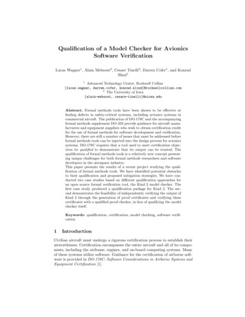
done by MD-Robotics for the engineering test of the SPDM.This is an interesting option but matching the frequency re-A)sponse of the space robot is difficult. In addition, the SPDMis mounted itself on the Canadarm 2 which is very flexible.A self-balancing system is not able to represent the flexible{Ws}Worksitealso by DLR [5] and NASA [6].The HLS simulator consists of a rigid robit with its con-mands to the SPDM simulator which predicts a corresponding motion response. The resulting SPDM endpoint motionthen becomes a setpoint for the rigid robot controller.The contact forces are measured using force/moment sensors and fed back into the simulator to allow the dynamicsimulation engine to react to external contact forces. Thisconcept is very flexible since it can accommodate vibrationPayloadpsmotion of the base. The last option is to use hardware-inthe-loop simulation (HLS) as done by the CSA [3],[4]) buttrol, a simulator for Canadarm2/SPDM dynamics and a visualisation engine. The SPDM operator sends joystick eps{Wr}WorksiteMockupof the space robot base or other phenomena. It can also Figure 1: Space Manipulator (A) and Terrestrial Manipulabe used to represent different space robots. The main dif- tor (B) performing contact task.ficulty in HLS is to have good performance while keepingthe system stable in free space and in contact. This type oferation. Cartesian position/velocity feedback is used in adsimulation creates instability problems similar to the casedition as a corrector to improve the system response withinof force control with a force reflecting master/slave systemthe bandwidth of interest. The control approach is presentedin teleoperation.in details in input [7].The CSA is using a cartesian feedback linearisation techFigure 1A illustrates a space manipulator handling a paynique with acceleration input ([7],[8]). This gives good perload. The space robot is typically flexible and redundant.formance and good stability. However, it requires a stiffFigure 1B illustrates the control approach. It shows arobot with high tracking accuracy, a good torque controllerground robot performing a contact tasks while emulatingand the ability to implement or access the robot controllerthe dynamics of the space robot. The contact forces areat the lowest level to achieve a fast sampling time.measured and fedback to the space robot controller (see figure 2.2Controller for Dynamics EmulationIn reality, the dynamics of robot manipulators is highlynonlinear. In addition to its inherent dynamic coupling,more severe phenomena such as joint friction and actuaThe rigid robot (terrestrial robot) control synthesis is of tor dynamics usually limit the ability to properly model andprime importance in the HLS concept. Since the idea is control manipulators. In the case where friction is dealt withto replicate the dynamics of the space robot with the ter- using model-based friction compensation or through localrestrial robot performing the contact task, the control algo- feedback of joint torque sensor signals, the method still aprithm must be such that the controlled terrestrial robot is plies. In that case, neglecting joint friction compensation ertransparent in the frequency band of interest for the analy- rors, the generic dynamic equation for a rigid ground robotsis required. The control approach presented in this paper (terrestrial robot) isconsists in forcing the terrestrial robot to behave like thesimulated space robot by commanding its Cartesian accel-MG (qG )q̈G hG (qG , q̇G ) BG uG(1)
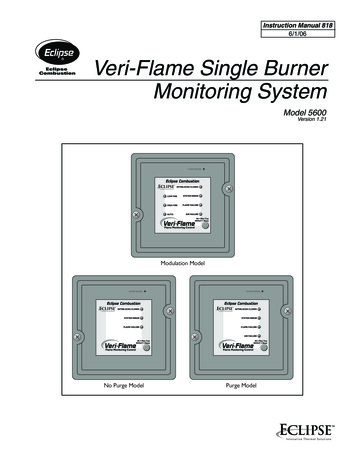
Joystick uGBG τGFG1Cartesian Vel.where JTG Measured Contact round RobotTip AccelerationXTip,SXTip,S XTip,SGroundRobotLinearControllerGround GroundRobotKinematicsHere, qG are the joint coordinates, MG is the inertia matrix,Ground Robot Joint Anglesand RateshG is a vector containing all nonlinear effects, JG is the manipulator Jacobian, τ G is the vector of control force/torques Figure 2: Cartesian Feedback Linearization with Acceleration Controllerand FG is the vector of force/torque applied to the end effector.To apply the acceleration command control, the groundrobot is first decoupled in Cartesian space through jointlevel nonlinear feedback as presented in [9]. The nonlinearfeedback law to achieve Cartesian decoupling is given byˆτ G ĥG ĴTG F̂G M̂G Ĵ 1G (γ J̇G q̇G )(2)where γ represents the new control input to the linearisedrobot. Applying the linearisation law (2) to the robot dynamics (1), the motion is then described byẌG γ JG q̈G J̇G q̇GFigure 3: Symofros Architecture(3)where γ is identified as the desired tip acceleration of therigid robot and represents the error in linearisation. The 3.1desired acceleration is defined by ConceptThe main philosophy behind the code development is the division of the system in functionalities (or modules). Eachmodule can be developed and tested quickly and indewhere X represents a combination of the angular and linear pendently in simulation using Symofros-Simulation undermotion. For the error in orientation, the rotation matrices Simulink. The modules are categorized in different levelsof libraries that facilitate unit testing, configuration manmust be used to compute an orientation error vector.γ ẌS Kv ẊS ẊG Kp (XS XG )3(4)Software Development and Implementationagement and integration. To develop the controller, a realistic model of the robot has been developed using SymofrosDynamics. Therefore, we have a calibrated (kinematicallyand dynamically) simulation model of the robot having thesame input/output signals as the real robot. This allows toThe control system development and implementation is run a pure non real time simulation of the overall system todone using Symofros environment [11],[12]. As shown in first assess that a given module can be integrated in the mainfigure 3, Symofros is used from the development stage up diagram. The next step consists in generating the code forto the real-time implementation phase of the project. The the real time target but for pure simulation with no hardwaremain goal behind this approach is to minimize as much as to test different simulation runs or controller gains with realpossible any hand recoding and to go from the simulation time performance. Afterward, we replace the pure simulaused in the development to the real-time code used in the tion blocks with the real hardware block and we generatethe code to run hardware in the loop in real time.control of the rigid robot.
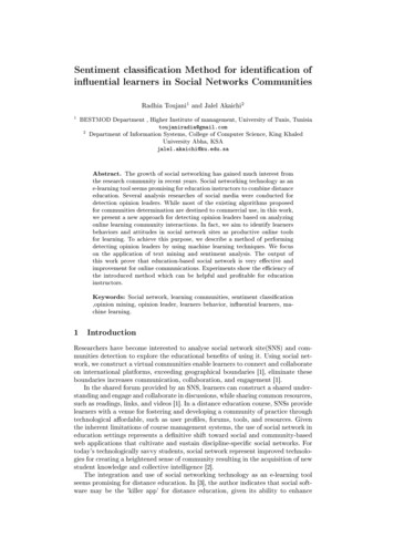
The main objective for Symofros architecture was to design a real time, distributed and open environment with thepossibility to run in real time or in non real time, not theopposite. Targetting a real time environment influences theapproach taken, for example the first level hierarchy of theI/O1000 HzSimulink diagram represents the various CPUs on which thediagram will be splited and the code generated.With the approach described above, a single SIMULINKdiagram represents the simulation, the implementation, theCSAcode running on the real time platform and as a byproduct the report describing the diagram can be generated. Inbetween the CPUs. Then, the functionalities (controllers,safety system, etc) are components that are sourced from20 HzSMT Hub100 Mbps EthernetSMT-OS (SGI)SMT-SIM(Origin 200)SMT-VIS(ONYX)FireWire1000 HzMOCterms of configuration management, this approach has a lotto offer. We initially define the input/ouput data -CS: ClusterController (NT)libraries representing modules that have been unit tested.3.2ImplementationFigure 4: Computer Architecture for the Space Robot Dynamics EmulationWe are using a heterogeneous computer environment tomaximize the use of existing CSA simulation facilities (see gency position controller is also running on Node 1. Nodefigure. 4). The controller of the terrestrial robot is running 2 runs the high level controller (the feedback linearisation)on a cluster of six Pentium computers running under QNX. and a state machine to manage the operational modes of theThe real-time simulator of the space robot uses the MSS rigid robot. This node has two firewire cards: one for theOperation and Training Simulator (MOTS). The dynamic communication with other computers of the cluster and oneengine of MOTS is running on a SGI Origin 200 machine for the communication with SPDM robot simulator. Node 3with four processors while the visual engine is running on contains the low level controller of the OTCME (the robota SGI Onyx machine with four processors. The Origin 200 end-effector). The gravity compensation and the forwardis running as a slave node to the cluster of Pentium com- kinematics, both using the Symofros model of the robot, areputers. The connection between the Origin 200 and all the also calculated on this node. Node 4 contains all the necesPentium is via a Firewire link. Since the visual and the hu- sary code for the visual environment, namely control of theman interface do not require high speed communication, a camera views. Finally, Node 5 runs a Symofros model offast ethernet link is used. The architecture is very modular the space robot that can be used instead of the SMT-Simsince the user can decide on which CPU each module will model. Both space robot models, SMT-Sim and Symofros,run. For more details on system architecture hardware and can run at the same time. The actual one tracked by theSMT robot is selected from a switch in the console. Node 6software see [11].The allocation of the nodes is as follows. The low-level is used for compilation and as a backup node.controller is running on the Node 1. This node also conThe fastest sampling frequency in the system is 1000 Hz.tains a timer card for the hardware synchronisation of all This is a MOTS requirement to ensure stability of the spaceCPUs. Node 1 also contains most of the Input/Output (I/O) robot simulator since a Euler integration method is used.of the robot, the remaining I/O being on Node 2. Node 1 Other parts of the system do not required to run at such a fastruns both the low level torque controller and the simulation rate. Our Symofros architecture is able to handle multi-ratemodel. The user selects the mode of operation, simulation systems in a multi CPUs environment (i.e. many differentor hardware, from the console and it can be changed on the rates on many different CPUs) while maintaining interCPUfly during the operation. A safety machine with an emer- synchronisation. While the code running on the Pentium
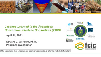
Figure 5: STVF Testbed Manipulatorcluster is directly managed by Simulink, the code runningon MOTS uses its owns process management system developed by CAE Electronics. This system also allows multipletime band simulation.Figure 6: Square Peg InsertionA standard Graphical User Interface provided withinIn this scenario, the worksite is mounted on a rigid forceSimulink and RT-Lab allows the user to control the execution of the simulator. A key element is the tools available for plate to accurately measure contact forces and moments.data acquisition: real time data logging of signals, snapshot This means that we have a very stiff robot contacting a rigidof all the signals from all the CPUs and online parameter worksite, controlled in such a way to replicate the dynamicstuning. In addition, an application program interface (API) of a flexible system. The peg is positioned a few centimetersallows the interface to third party GUIs, e.g. Labview or above the worksite with a small misalignment. The SPDMis commanded to move in the axial direction only.custom designed GUIs.44.1Experimental ResultsInitially, the robot is moving in free space. Then, aftertime equal 8 seconds, the end effector contacts the worksite for the square peg (in the z direction). The insertionitself happens between time 8 seconds and 30. An extrac-Square Peg Insertiontion occurs after time equals 30 seconds and the peg is fullySince an off-the-shelf industrial manipulator could not meet extracted at time 48 seconds. After about 20 s, the peg hitsour requirements, a custom hydraulic manipulator (see fig- the side of the worksite and the force moment accommoure 5) was build by International Submarine Engineering dation scheme of the SPDM realigns the peg to permit theLtd, a Canadian company with significant experience in de- insertion. The various forces exerted during the insertionlivering hydraulic manipulators for submersible and terres- are friction forces (mainly x and y direction) and as welltrial applications. The key issues for the ground robot de- the applied force in the z direction. The force is stabilisedsign for HLS and for SPDM emulation can be found in [13]. around 200 N (z direction). It can be seen on figures 7 andA square peg insertion case was tested experimentally 8 that the terrestrial robot (SMT) is tracking the space robot(see figure 6)and is presented below. The tolerance be- (SPDM) with a good accuracy. The Experimental resultstween the square peg and the worksite is 0.25mm. Figure 7 errors are presented in table 1. The system positionningshows the position of the simulated SPDM and of the ter- specifications for the project are 6 mm and 0.5 degrees. Alrestrial robot (SMT) while figure 8 shows their respective though the various velocities and forces seem low, they arevelocities. Finally figure 9 shows the resulting experimen- typical of operational velocities of the SPDM in space.tal forces measured during the insertion.Finally, from figure 9, the vibrations observed are the
Square PEG insertionSquare PEG insertion50SMT FeedbackSpace Robot CMD1.09Force in X (N)X Position (m)1.0951.0851.080102030Time (s)4050 50600102030Time (s)4050600102030Time (s)4050600102030Time (s)40506050SMT FeedbackSpace Robot CMDForce in Y (N)Y Position (m)0.0150.010.00500102030Time (s)40500 5060SMT FeedbackSpace Robot CMD 0.1Force in Z (N)Z Position (m)300 0.15 0.2 0.250102030Time (s)405060Square PEG insertionDirectionX Position (mm)Y Position (mm)Z Position (mm)X Squew angle (deg)Y Squew angle (deg)Z Squew angle (deg)X Velocity (m/s)Y Velocity (m/s)Z Velocity (m/s)X Angular Velocity(deg/sec)Y Angular Velocity(deg/sec)Z Angular Velocity(deg/sec)X Velocity (m/s)SMT FeedbackSpace Robot CMD0 0.010102030Time (s)405060Y Velocity (m/s)0.020 0.01 0.02Z Velocity (m/s)SMT FeedbackSpace Robot CMD0.010102030Time (s)405060SMT FeedbackSpace Robot CMD0.010 0.01 0.020102030Time (s)40500Figure 9: Experimental Forces for Square Peg Insertion0.02 0.02100 100Figure 7: Experimental Positions for Square Peg 0.0190.00130.0020.0120.00070.001Figure 8: Experimental Velocities for Square Peg InsertionTable 1: Errorsones of the space robot itself with the current force momentaccomodation gains. This problem will be solved by ad- robot system, namely the friction, the weight of the groundjusting the space robot force moment accomodation gains robot (1650 kg), the compressibility of the oil that limit the(as the SMT robot is emulating the behavior of the Space performance of the torque controller as well as the limitation is due to the dynamic model estimation errors.robot performing the contact task).4.2Bandwidth Limit5ConclusionsThere is a limit in the bandwidth to which the Ground robotcan emulate the Space Robot. Figure 10 present the results We demonstrated that a space robot can be emulated by aof the emulation of the space robot by the ground robot terrestrial manipulator using a hardware-in-the-loop simuwhile injecting band limited white noise (up to 3 Hz) as lation technique. We have shown that the controller needsan input command to the ground robot. This limit is mainly to cancel the dynamics of the terrestrial robot. This is donecaused by the various hardware components of the ground through a cartesian feedback linearisation technique with
Translational Acceleration Tracking and within [0.1 3] HzX Accel error (dB)420 2 4 1010Y Accel error (dB)10Freq. (Hz)4ing industrial robots,” in Fifth International Symposium on Artificial Intelligence, Robotics and Automation in Space (M. Perry, ed.), (Noordwijk, The Netherland), pp. 681–686, ESA Publication Division, 1999.20 2 4 101010Freq. (Hz)4Z Accel error (dB)[5] R. Krenn and B. Schäefer, “Limitations of hardwarein-the-loop simulations of space robotics dynamics us-[6] S. Ananthakrishnan, R. Teders, and K. Alder, “Role ofestimation in real-time contact dynamics enhancementof space station engineering facility,” IEEE Robotics& Automation Magazine, pp. 20–28, September 1996.20 2 4 101010Freq. (Hz)Figure 10: Experimental Free Space Bandwidththe acceleration of the space robot endpoint as input. Wealso discussed the critical aspect of the implementation ona real robot. We have used Symofros, allowing quick prototyping and real-time implementation. We demonstrated thevalidity of our approach by presenting experimental resultsshowing a square peg insertion task.References[1] M. Stieber, S. Sachdev, and J. Lymer, “Robotics architecture of the mobile servicing system for the International Space Station,” in Proceeding of the 31st Inter-[7] J. de Carufel, E. Martin, and J.-C. Piedbœuf, “Control strategies for hardware-in-the-loop simulation offlexible space robots,” IEEE Proceedings-D: ControlTheory and Applications, vol. 147, no. 6, pp. 569–579,2000.[8] F. Aghili and J.-C. Piedbœuf, “Hardware-in-loop simulation of robots interacting with environment via algebraic differetial equation,” in 2000 IEEE/RSJ International Conference on Intelligent Robots and Systems, (Takamatsu , Japan), pp. 1590–1596, 30 October- 5 November 2000.[9] O. Khatib, “A unified approach for motion and forcecontrol of robot manipulators: The operational spaceformulation,” IEEE Transactions on Robotics and Automation, vol. RA-3, no. 1, pp. 43–53, 1987.national Symposium on Robotics (ISR 2000), (Mon- [10] J. G. de Jalon and E. Bayo, Kinematic and Dynamictreal, Quebec), pp. 416–421, Canadian Federation ofSimulation of Multibody Systems. Springer-Verlag,Robotics, May 2000.1989.[2] O. Ma, K. Buhariwala, N. Roger, J. MacLean, and [11] M. Doyon, R. L’Archevêque, and J.-C. Piedbœuf,R. Carr, “MDSF- A generic development and simu“SPDM task verification facility: Computer architeclation facility for flexible, complex robotic systems,”ture and real time implementation,” in DASIA 2000 Robotica, vol. 15, pp. 49–62, 1997.Data Systems in Aerospace, (Montreal, Canada), 22[3] J.-C. Piedbœuf, J. de Carufel, F. Aghili, and E. Dupuis,26 May 2000.“Task verification facility for the Canadian special [12] R. L’Archevêque, M. Doyon, J.-C. Piedbœuf, andpurpose dextrous manipulator,” in 1999 IEEE International Conference on Robotics and Automation, (Detroit, Michigan), pp. 1077–1083, 10-15 May 1999.Y. Gonthier, “SYMOFROS: Sofware architecture andreal time issues,” in DASIA 2000 - Data Systems inAerospace, (Montreal, Canada), 22-26 May 2000.[4] F. Aghili, E. Dupuis, J.-C. Piedbœuf, and J. de Carufel, [13] D. Rey, J.-C. Piedbœuf, and E. Jackson, “Manipula“Hardware-in-the-loop simulations of robots performtor design consideration for space robot emulation oning contact tasks,” in Fifth International Symposiumground,” in International Symposium on Robotics andon Artificial Intelligence, Robotics and Automation inAutomotion, ISRA’2000, (Monterey, Mexico), pp. 41–Space (M. Perry, ed.), (Noordwijk, The Netherland),47, 10-12 November 2000.pp. 583–588, ESA Publication Division, 1999.
ment Units (ORU), the components of the ISS systems re-placeable on orbit. The SPDM will operate directly con-nected to the ISS or to the tip of the Canadarm 2. Both the Canadarm 2 and the SPDM are tele-operated by an opera-tor located inside the ISS. Due to the important flexibility in the Canadarm 2/SPDM system, all insertion/extraction