Transcription
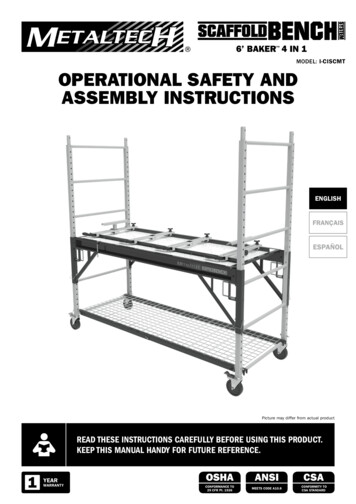
6’ BAKER 4 IN 1 MODEL: I-CISCMTOPERATIONAL SAFETY ANDASSEMBLY INSTRUCTIONSENGLISHFRANÇAISESPAÑOLPicture may differ from actual productREAD THESE INSTRUCTIONS CAREFULLY BEFORE USING THIS PRODUCT.KEEP THIS MANUAL HANDY FOR FUTURE REFERENCE.1YEARWARRANTYOSHACONFORMANCE TO29 CFR Pt. 1926ANSICSAMEETS CODE A10.8CONFORMITY TOCSA STANDARD
2OPERATIONAL SAFETYREAD BEFORE BEGINNING ASSEMBLY.FAILURE TO UNDERSTAND AND FOLLOW ALL SAFETY RULES AND ASSEMBLY INSTRUCTIONS COULDRESULT IN SERIOUS INJURY OR DEATH.METAL CONDUCTS ELECTRICITY:Do not use this equipment where contact may be made with power lines or other live electrical circuits.DO NOT OVERLOAD:This scaffolding is designed to support a maximum load of 1,100 lb (500 kg). The maximum load capacity decreases whenstacking units: one unit high 1,100 lb (500 kg) / two units high with guardrails 922 lb (419 kg) / three units high withguardrails 803 lb (365 kg).OPERATION AND SAFETY Do not use this equipment if you are in poor health,taking medications, drugs, or have been consumingalcohol, all of which may impair your ability to worksafely on this product. Always use this scaffold in conformity with local ornational legislation which applies. Inspect before use. Do not use scaffold if damaged orparts are missing. Examine thoroughly to make sure unit is properlyset up. Always use casters locked to the side frames withthe locking pins. Securely lock all braces and deck before each use. The deck must be fully seated within the braces andlocked with the security latches before each use.The wood deck must be checked for loose or missingsteel frame components, large holes or thin spotswhere the plywood has been worn. Worn or damageddeck must be replaced promptly.Braces must be inspected to ensure lockingmechanisms are working correctly. Any brace withdamaged locking devices should not be used.Never flip the reversible platform with a miter sawinstalled. You could damage your equipment.Before flipping the reversible platform, the platformmust be free of tools and materials.Never sit, stand or climb on the shelf.Always secure the shelf braces using the locking pins.Check that the shelf wires are well inserted in theholes of each brace.The lower section of the ladder must be installedunder the upper section of the ladder and thespring-lock mechanism that secures both partsmust be engaged in the scaffold structure.When used as a storage rack, this scaffoldingmust be secured by the anti-tip assemblysupplied.Install the anti-tip assembly under the highestrung of the scaffold.For your own safety, read and understand themiter saw instruction manual before using theuniversal miter saw stand.Always fasten the miter saw to the mountingbrackets as instructed.Always lock the mounting brackets in place beforeusing the miter saw.Piece supports must be locked with the tighteningknobs. Always use outriggers when stacking units.There must be a minimum of two side bracesinstalled on each scaffold level and evenly spacedthroughout the scaffold. Lack of adequate bracingcould cause scaffold to collapse.Guardrails must be installed on all open sides of awork deck where a person could fall from a heightof 6 ft (1.8 m) or more. Do not climb unless all casters are in locked position.Always remove casters when using this scaffoldingon stairs.Always climb up or down the scaffolding sideframes facing towards the ladder.Always keep the body centered between the sideframe’s uprights.Always keep three points of contact with the ladder.When climbing from the exterior, always step overthe ladder to access the platform.Always keep the body close to the ladder asshown in the “Maximum Climbing Distance” table.Always keep a steady pace when climbing.Do not create a swaying motion when climbing. Erect to be plumb on firm and level surface. This scaffold must be used on a firm surface that isfree of pits, debris, holes or obstructions. Never place anything under or attach anythingto this scaffold to increase height or to adjust touneven surfaces. Acids are corrosive and can seriously affectstrength. Do not expose this scaffold to corrosivesubstances. This product is designed to be used and storedindoors. The use or the exterior storage could resultin structural deterioration due to rust and damagedor can lead to rotting wood framing. Store dry. Keep scaffold free of debris and unnecessaryequipment. Keep your body close to the scaffold as you climb. Do not overreach. Always keep body centeredinside structure of scaffold. Remove or fasten all tools, material or equipmentbefore moving. Use extra caution when moving toavoid tipping. Never try moving this scaffold while standing on it. Never move a scaffold with a worker within. Do not use powered devices to propel this scaffold.Use extra caution near operating machinery. Do not use if the surface is not firm and level. Do not use in inclement weather or high winds. Maintain a firm grip while climbing. Do not modify the scaffold or any of its components. Do not use the scaffold as a footbridge. Never sit, stand or climb on the miter saw stand sideof the platform. It is strongly recommended to be two people to liftand flip the reversible platform. Lock the miter saw mounting brackets beforeflipping the reversible platform.MAXSCAFFOLDMAXIMUM LOADCAPACITY: 1,100 lb(500 kg)ALWAYS KEEP THEBODY CLOSE TO THELADDER AS SHOWNIN THE “MAXIMUMCLIMBING DISTANCE”TABLE.GUARDRAILS RAILS MUST BEINSTALLED ON ALL OPEN SIDESOF A WORK PLATFORM WHEREA PERSON COULD FALL FROM AHEIGHT OF 6 FT (1.8 M) OR MOREALWAYS CLIMBUP OR DOWN THESCAFFOLDING SIDEFRAMES FACINGTOWARDS THELADDER.DO NOT CREATE ASWAYING MOTIONWHEN CLIMBING.METAL CONDUCTSELECTRICTYALWAYS KEEP BODYCENTERED INSIDESTRUCTURE OF UNITDO NOT USE ININCLEMENTWEATHEROR HIGH WINDSACIDS ARECORROSIVE.DO NOT EXPOSEUNIT TO CORROSIVESUBSTANCESUNIT SHALL ONLYBE USED ONFIRM AND LEVELSURFACESNEVER TRY MOVINGTHE UNIT WHILESTANDING ON ITERECT ON FIRMAND LEVEL GROUNDNEVER PLACEANYTHING UNDEROR ATTACHANYTHING TO UNITREMOVE OR FASTEN TOOLS,MATERIAL OR EQUIPMENTBEFORE MOVING. NEVERMOVE A SCAFFOLD WITHWORKER WITHIN.DO NOT USETHE UNIT ASA FOOTBRIDGEALWAYS LOCKTHE ALL CASTERSBEFORE CLIMBINGALWAYS INSPECTBEFORE USEMAXMAX. 1,100 lb(500 kg)ALWAYS USEOUTRIGGERS WHENSTACKING UNITS.6’(1,8 M)All photos and drawings in this booklet are for reference purposes only. Refer to applicable OSHA, ANSI or CSA codes and regulations for the proper use of this equipment.
3REPLACEMENT PARTS AND HARDWAREFOR YOUR 6 FT. SCAFFOLDING (MODEL I-CISCMT)FGEDHBACAll the parts provided by our factories are genuine quality replacementparts. Using the chart to find the required part and its number and contactour customer service for ordering.PART NAMEPART NUMBERAPlatform securitylatch kitI-CISC902BLocking pinCCustomer Service1 800 363-7587customerservice@metaltech.coPART NAMEPART NUMBERFRear support kitI-CISCMT902I-CAS5PINGTightening knob kitI-CISCMT903Caster withlocking pinI-C1CAS5HSpring clip kitI-CISCMT904DU-lock kitI-CISC901Wing nut andcarriage bolt kitI-CISCMT905ETightening handle kitI-CISCMT901Anti-tip assembly &locking pin kitI-CISSU901
4AVAILABLE OPTIONS*SEE YOUR RETAILER FOR DETAILSPRODUCT CODEDESCRIPTIONPRODUCT l shelfI-CISO4Set of 14”outriggersI-IBBF4Set of 4 baseplatesI-CISO4TTSet of 46”outriggersI-IBSJP12H4Set of 4 levelingjacksI-ISEX4PPNCAS39” highextensionI-ISLInterior ScaffoldSafety brakeI-CISPTPlatform withtrap doorI-CISRLSupport rollerI-CISSUAdd-on shelfI-SBCScaffoldbench connector*Options not included, sold separately
56’ BAKER 4 EN 1 MODÈLE: I-CISCMTCONSIGNES DE SÉCURITÉ ETINSTRUCTIONS DE MONTAGEENGLISHFRANÇAISESPAÑOLL’image peut différer du produit réelLIRE SOIGNEUSEMENT CES INSTRUCTIONS AVANT D’UTILISER CE PRODUIT.CONSERVER CE MANUEL À PORTÉE DE MAIN POUR RÉFÉRENCE ULTÉRIEURE.1ANDE GARANTIEOSHAANSICSAEN CONFORMITÉ AVEC29 CFR Pt. 1926RENCONTRELA NORME A10.8CONFORME À LANORME CSA
CONSIGNES DE SÉCURITÉLIRE SOIGNEUSEMENT AVANT D’EFFECTUER LE MONTAGE.LA NON-COMPRÉHENSION ET LE NON-RESPECT DE TOUTES LES RÈGLES DE SÉCURITÉ ET DE TOUTESLES CONSIGNES D’ASSEMBLAGE PEUT ENTRAÎNER DES BLESSURES GRAVES OU MORTELLES.LE MÉTAL EST CONDUCTEUR D’ÉLECTRICITÉ :Ne pas utiliser cet équipement où il pourrait entrer en contact avec une ligne électrique ou une source de courant.ÉVITEZ LES SURCHARGES :Cet échafaudage est conçu pour soutenir une charge maximale de 1100 lb (500 kg). La capacité de charge maximale diminuelorsque des unités sont superposées: une unité de haut 1100 lb (500 kg) / deux unités de haut avec garde-corps 922 lb(419 kg) / trois unités de haut avec garde-corps 803 lb (365 kg).CONSIGNES ET SÉCURITÉ Ne pas utiliser cet équipement si vous êtes enmauvaise santé, si vous prenez des médicaments,ou êtes sous l’emprise de la drogue ou de l’alcool,cela pourrait nuire à votre capacité à travailler entoute sécurité sur ce produit. Se conformer à la législation locale ou nationalequi s’applique pour l’utilisation de ce typed’échafaudage. Inspecter avant utilisation. Ne pas utiliserl’échafaudage s’il est endommagé ou s’il manquedes pièces. Examiner soigneusement afin de s’assurer quel’échafaudage est assemblé correctement. Toujours fixer les roues aux cadres latéraux à l’aidedes tiges de verrouillage. S’assurer de toujours bien verrouiller traverses et lepont avant toute utilisation. Le pont doit être bien fixée aux traverses etverrouillée à l’aide des loquets de sécurité avanttoute utilisation. Le pont en contreplaqué doit être vérifié pours’assurer qu’il est en bon état, sans trou et usureexcessive. Qu’il ne manque pas de rebords au cadreen acier et aucun jeu entre les pièces. Tout pont uséou endommagé doit être remplacé. Les mécanismes de verrouillage des traversesdoivent être inspectés afin de s’assurer qu’ilsfonctionnent correctement. Toute traverse avecdispositif de verrouillage endommagé ne doit pasêtre utilisée. Un minimum de deux traverses doit être installéet régulièrement espacé sur chaque unitéd’échafaudage superposée. Un manque derenfort pourrait provoquer l’effondrement del’échafaudage. Ne jamais s’asseoir, se tenir debout ou grimper ducôté support de scie à onglet de la plateforme. Il est fortement conseillé de soulever et retournerla plateforme réversible à deux personnes. Verrouiller les dispositifs de fixation de scie à ongletsavant de retourner la plateforme réversible.Ne jamais retourner la plateforme réversibleavec une scie à onglets installée. Vous pourriezendommager votre matériel.Avant de retourner la plateforme réversible, s’assurerqu’elle est exempte d’outils et de matériaux.Ne jamais s’asseoir, se tenir debout ou grimper surl’étagère.Toujours verrouiller les traverses de l’étagère àl’aide des tiges de verrouillage.Vérifier que les grilles d’étagère soient bieninsérées dans les trous de chacune des traverses.La section inférieure de l’échelle doit être installéesous la section supérieure de l’échelle et lemécanisme de blocage à ressort qui sécurise lesdeux parties doit être engagé dans la structured’échafaudage.Lorsqu’il est utilisé comme étagère, cetéchafaudage doit être sécurisé à l’aide dudispositif anti-basculement fourni.Installer le dispositif anti-basculement sousl’échelon le plus haut de l’échafaudage.Pour votre propre sécurité, lire et comprendre lemanuel d’instructions de la scie à onglets avantd’utiliser le support de scie à onglets universel.Toujours fixer la scie à onglets aux dispositifs defixation comme indiqué.Toujours verrouiller en place les dispositifs defixation avant d’utiliser la scie à onglets.Les supports de pièce doivent être verrouillés àl’aide des molettes de serrage. Toujours utiliser stabilisateurs lorsque voussuperposez une unité à une autre. Des garde-corps devraient être installés sur tousles côtés ouverts d’un pont de travail d’où unepersonne pourrait tomber d’une hauteur de 6 pi(1,8 m) ou plus. Ne jamais monter si toutes les roues ne sont pasverrouillées. Toujours retirer les roues lorsque vous utilisez cetéchafaudage dans un escalier. Toujours monter ou descendre en faisant face àl’échelle des cadres latéraux de l’échafaudage. Toujours garder le corps centré entre les montants descadres latéraux. Ayez toujours trois points de contact avec l’échelle. Lorsque vous montez par l’extérieur, toujoursenjamber l’échelle pour accéder à la plateforme. Toujours garder le corps près de l’échelle commeindiqué dans le tableau «Distance maximale d’accès» Toujours garder un rythme soutenu lors de la montée. Ne pas créer un mouvement de balancement lorsde la montée. Installer sur une surface ferme, égale et de niveau. Cet échafaudage doit être utilisé sur une surfaceferme, sans creux, débris, trous ou obstacles. Ne rien placer et ne rien fixer à l’échafaudage afind’en remonter la hauteur ou d’égaliser une surfaceinégale. Les acides sont corrosifs et peuvent affectersérieusement la solidité. Ne pas exposerl’échafaudage à des substances corrosives.Ce produit est conçu pour être utilisé et entreposé àl’intérieur. L’utilisation ou l’entreposage à l’extérieurpourrait provoquer une détérioration structurelle parla rouille et endommager ou faire pourrir le bois de laplateforme. Entreposer au sec. Garder cet échafaudage libre de débris oud’équipement non nécessaire. Tenir votre corps près de l’échafaudage lorsquevous montez. Ne pas vous étirer. Garder votre centre de gravité àl’intérieur de la structure de l’échafaudage. Toujours enlever ou attacher outils, matériel ouéquipement avant de déplacer l’échafaudage.Soyez prudent lorsque vous déplacez l’échafaudageafin d’éviter qu’il ne bascule. Ne jamais essayer de déplacer l’échafaudage enétant dedans. Ne jamais déplacer avec un travailleur dansl’échafaudage. Ne pas se servir d’un engin à moteur pourpropulser l’échafaudage. Faire attention à laproximité de machineries. Ne pas utiliser si la surface n’est pas ferme et deniveau. Ne pas utiliser l’échafaudage par mauvais temps oupar grand vent. Toujours se tenir fermement en grimpant. Ne pas modifier l’échafaudage ou l’une de sescomposantes. Ne jamais utiliser l’échafaudage comme passerelle.MAXCAPACITÉNOMINALE: 1100 lb(500 kg) TOUJOURS GARDERLE CORPS PRÈS DEL’ÉCHELLE COMMEINDIQUÉ DANS LETABLEAU «DISTANCEMAXIMALE D’ACCÈS»DES GARDE-CORPS DOIVENT ÊTREINSTALLÉS SUR TOUS LES CÔTÉSOUVERTS D’UNE PLATEFORME D’OÙUNE PERSONNE POURRAIT TOMBERD’UNE HAUTEUR DE 6 PI (1,8 M) OUPLUSTOUJOURS MONTEROU DESCENDREEN FAISANT FACEÀ L’ÉCHELLE DESCADRES LATÉRAUXDE L’ÉCHAFAUDAGE. PAS CRÉER UNNEMOUVEMENT DEBALANCEMENT LORSDE LA MONTÉE.LE MÉTAL ESTCONDUCTEURD’ÉLECTRICITÉGARDER SONCENTRE DE GRAVITÉÀ L’INTÉRIEUR DELA STRUCTURE DEL’ÉCHAFAUDAGENE PAS UTILISERL’ÉCHAFAUDAGE PARMAUVAIS TEMPS OUPAR GRAND VENTNE PAS EXPOSERL’ÉCHAFAUDAGEÀ DES SUBSTANCESCORROSIVESNE PAS UTILISERSUR UNESURFACE QUIN’EST PAS DENIVEAUNE JAMAIS ESSAYERDE DÉPLACERL’ÉCHAFAUDAGE ENÉTANT DEDANSINSTALLERL’ÉCHAFAUDAGE SURUNE SURFACE FERME,ÉGALE ET DE NIVEAUNE RIEN PLACEROU FIXER POURREMONTER LAHAUTEUR DEL’ÉCHAFAUDAGEATTACHER OU ENLEVER OUTILS,ÉQUIPEMENT LORS D’UNDÉPLACEMENT. NE JAMAISDÉPLACER AVEC UN TRAVAILLEURDANS L’ÉCHAFAUDAGENE JAMAIS UTILISERL’ÉCHAFAUDAGECOMME NT UTILISATIONNE JAMAIS MONTER SILES ROUES NE SONT PASVERROUILLÉESTOUJOURS UTILISERDES STABILISATEURSLORS DE LASUPERPOSITIOND’UNITÉS.MAXMAX. 1100 lb(500 kg)6’(1,8 M)Toutes les photos et dessins de cette brochure sont à titre indicatif seulement. Reportez-vous aux codes et règlements applicables OSHA, ANSI ou CSA concernant l’utilisation correcte de cetéquipement.
7PIÈCES DE RECHANGE ET QUINCAILLERIEPOUR VOTRE ÉCHAFAUDAGE DE 6 PI. (MODÈLE I-CISCMT)FGEDHBACToutes les pièces fournies par nos usines sont de la même qualité queles pièces d’origine neuves. Utilisez le tableau pour trouver la pièce requiseet son numéro et contactez notre service client pour commander.NOM DE LA PIÈCENUMÉRO DEPIÈCEAEnsemble loquet desécurité de plateformeI-CISC902BTige de verrouillageCService à la clientèle1 800 363-7587serviceclient@metaltech.coNOM DE LA PIÈCENUMÉRO DEPIÈCEFAssemblagede support arrièreI-CISCMT902I-CAS5PINGAssemblage de molettede serrageI-CISCMT903Roue avec tigede verrouillageI-C1CAS5HEnsemble de blocageà ressortI-CISCMT904DEnsemble de tige deverrouillage en UI-CISC901Ensemble d’écrouspapillon et boulonsI-CISCMT905EAssemblage depoignée de serrageI-CISCMT901Dispositifanti-basculement avectige de verrouillageI-CISSU901
8OPTIONS DISPONIBLES*CONSULTEZ VOTRE DÉTAILLANT POUR PLUS DE DÉTAILSCODE DU PRODUITDESCRIPTIONCODE DU PRODUITDESCRIPTIONI-CISGRJPSystèmede garde-corpsI-CISTRPlateau à outilsI-CISO4Ensemblede stabilisateursde 14”I-IBBF4Ensemble de 4plaques de baseI-CISO4TTEnsemblede stabilisateursde 46”I-IBSJP12H4Ensemble de4 vérins à visI-ISEX4PPNCASExtensionde 39” de hautI-ISLFrein de rme avectrappe d’accèsI-CISRLSupportà urScaffoldbench *Options non-incluses, vendues séparément
96’ BAKER 4 EN 1 MODELO: I-CISCMTDIRECTIVAS DE SEGURIDADE INSTRUCCIONES DE MONTAJEENGLISHFRANÇAISESPAÑOLLa imagen puede variar del producto realLEA ATENTAMENTE ESTAS INSTRUCCIONES ANTES DE UTILIZAR ESTEPRODUCTO. CONSERVE ESTE MANUAL COMO REFERENCIA ULTERIOR.1AÑODE GARANTÍAOSHAANSICSACUMPLE CON 29CFR PT. 1926ENCUENTRALA NORMA A10.8CONFORMEA LA NORMA CSA
10DIRECTIVAS DE SEGURIDADLEA ATENTAMENTE ANTES DE COMENZAR EL MONTAJE.LA FALTA DE COMPRENSIÓN Y RESPETO A TODAS LAS REGLAS DE SEGURIDAD Y EL INCUMPLIMIENTODE LAS INSTRUCCIONES DE MONTAJE PUEDEN CAUSAR LESIONES GRAVES O MORTALESEL METAL ES CONDUCTOR DE ELÉCTRICIDAD:No use este equipo donde pueda estar en contacto con líneas de electricidad o circuitos eléctricos vivosNO SOBRECARGUE:Este andamio está concebido para soportar una carga máxima de 1100 lb (500 kg). La capacidad de carga máximadisminuye cuando las unidades se sobreponen: una unidad de altura 1100 lb (500 kg) / dos unidades de altura con barrasde seguridad 922 lb (419 kg) / tres unidades de altura con barras de seguridad 803 lb (365 kg).CONSIGNAS DE SEGURIDADNo utilice este equipo si se encuentra mal, si estátomando medicamentos, o bajo la influencia delalcool o drogas, esto podría rebajar su capacidadpara trabajar en toda seguridad con este equipo. Ajustarse a la legislación local o nacional que seaplica para la utilización de este tipo de andamio. Inspeccione antes de utilizar. No use el andamio siestá dañado o falto de piezas. Examine con detalle que el andamio esté montadocorrectamente. Siempre bloquee las ruedas a los cuadros lateralescon la ayuda de los pestillos de seguridad. Asegúrese que todos los travesaños y laplataforma están bien cerrados (bloqueados) entresí antes de cada utilización. La plataforma tiene que estar bien sentada entrelos travesaños y bloqueada con los pestillos deseguridad antes de cada utilización.La plataforma en contrachapado debe serverificada para asegurarse su buen estado sinque tenga agujeros ni usura excesiva. Que no lefalten bordes al cuadro de acero ni haya juego deholgura entre las piezas. Toda plataforma gastadao dañada debe ser remplazada.Los travesaños de seguridad deben ser verificadospara asegurarse que funcionan correctamente. Todotravesaño con un dispositivo de cierre dañado no debeser utilizado. Un mínimo de dos travesaños deben ser instaladosequidistantes sobre cada unidad del andamio. Unafalta de soporte entre las plataformas puede provocarel derrumbamiento del andamio.Nunca se siente, se pare o se trepe sobre ellado del soporte de la sierra ingletadora de laplataforma.Se recomienda fuertemente levantar y voltear laplataforma reversible entre dos personas.Bloquee los soportes de montaje de la sierraingletadora antes de voltear la plataforma reversible.Nunca gire la plataforma reversible con una sierrade inglete instalada. Podría dañar su equipo.Antes de voltear la plataforma reversible, asegúreseque esté libre de herramientas y materiales.Nunca se siente, se pare, o se trepe sobre el estante.Siempre asegure los travesaños de la repisa conlos pasadores de bloqueo.Verifique que las rejillas de la estantería estén bieninsertadas en los orificios de cada travesaño.La sección inferior de la escalera debe instalarsedebajo de la sección superior de la escalera,y el mecanismo de bloqueo de resorte queasegura ambas partes debe ser enganchado en laestructura del andamio.Cuando se utiliza como estante, este andamiodebe asegurarse con el dispositivo antivuelcoproporcionado.Instale el dispositivo antivuelco sobre el peldañomás alto del andamio.Para su propia seguridad, lea y comprenda elmanual de instrucciones de la sierra de ingleteantes de utilizar el soporte universal de la sierraingletadora.Fije siempre la sierra ingletadora a los soportes demontaje según las instrucciones.Siempre bloquee los sujetadores en su lugar antesde usar la sierra ingletadora.Los soportes de las piezas deben estarbloqueados con las perillas de ajuste. Siempre use lo estabilizadores cuando sobrepongauna unidad a la otra. Las barandillas de seguridad deben ser instaladassobre todos los lados abiertos de una plataformade trabajo, donde una persona podría caer de unaaltura de 6 pies (1.8 m) o más. Nunca se suba si las 4 ruedas no están bloqueadas.Siempre retire las ruedas cuando utilice este andamioen una escalera.Siempre suba o baje de frente a la escalera de loslados de los cuadros laterales del andamio.Siempre guarde el cuerpo centrado entre la partesuperior de los cuadros laterales.Siempre tenga tres puntos de contacto con la escalera.Cuando usted suba por el exterior, siempre pasepor encima de la escalera para acceder a laplataforma.Siempre mantenga el cuerpo cerca de la escaleratal como se indica en la tabla “Distancia máximade acceso”.Siempre mantenga un ritmo constante cuando suba.No cree un movimiento de balanceo cuando suba.Instale el andamio sobre una superficie firme,plana y a nivel. Este andamio debe ser utilizado sobre unasuperficie firme, sin baches, escombros, hoyos uobstáculos. Nunca añada o ponga nada bajo el andamio paraaumentar la altura o igualar una superficie desigual. Los ácidos son corrosivos y pueden seriamenteafectar la integridad y la fuerza de los materialesusados en el andamio. No exponga el andamio asubstancias corrosivas.Este producto está diseñado para ser utilizado yalmacenado en interiores. El uso o almacén en elexterior puede deteriorar la estructura por el óxidoy dañar o permitir que la madera de la plataformase pudra. Almacenar en lugar seco. Mantenga el andamio libre de todo escombro yequipo innecesario. Mantenga el cuerpo cerca del andamio mientras sube. No trate de alcanzar estirándose. Mantenga su centrode gravedad interior de la estructura del andamio. Siempre recoja o sujete herramientas, materialo equipo antes de desplazar el andamio. Seaprudente en el desplazo evitando que bascule. Nunca desplace el andamio estando subido en él. Nunca desplace el andamio con un trabajadorsubido en él. No se sirva de un aparato motorizado parapropulsar el andamio. Tenga cuidado conmaquinaria que esté próxima. No utilice el andamio si el suelo no es firme y a nivel. No utilice el andamio si hace mal tiempo ni convientos fuertes. Siempre sujétese firmemente cuando se suba. No modificar el andamio ni ninguno de suscomponentes. Nunca utilice el andamio como puente.MAXCAPACIDADNOMINAL 1100 lb(500 kg)SIEMPRE MANTENGAEL CUERPO CERCADE LA ESCALERA TALCOMO SE INDICA ENLA TABLA “DISTANCIAMÁXIMA DE ACCESO”.BARANDILLAS DE SEGURIDAD DEBENSER INSTALADAS SOBRE TODOSLOS LADOS ABIERTOS DE UNAPLATAFORMA, DONDE UNA PERSONAPODRÍA CAER DE UNA ALTURA DE 6PIES (1.8 M) O MÁS.SIEMPRE SUBA OBAJE DE FRENTE ALA ESCALERA DELOS LADOS DE LOSCUADROS LATERALESDEL ANDAMIO.NO CREE UNMOVIMIENTO DEBALANCEO CUANDOSUBA.EL METAL ESCONDUCTORDE ELÉCTRICIDADMANTENGA SU CENTRO DEGRAVEDAD AL INTERIOR DE LAESTRUCTURA DEL ANDAMIONO UTILICE ELANDAMIO SI HACEMAL TIEMPO NI CONVIENTOS FUERTESNO EXPONGA EL ANDAMIO A MATERIASCORROSIVASNO UTILICE SOBREUNA SUPERFICIEQUE NO ESTÉ ANIVELNUNCA TRATE DE DESPLAZAR ELANDAMIO ESTANDO DENTROINSTALE EL ANDAMIOSOBRE UNA SUPERFICIE FIRME, PLANA Y ANIVELNO PONGA NIFIJE NADA PARAAUMENTAR LAALTURA DELANDAMIORECOJA O SUJETE HERRA MIENTAS, Y EQUIPO ANTES DEUN DESPLAZAMIENTO. NUNCADESPLACE EL ANDAMIO CON UNTRABA JADOR SUBIDO EN ÉLNUNCA UTILICE ELANDAMIO COMOPUENTEEXAMINE CONDETALLE ELANDAMIO ANTES DESU UTILIZACIÓNNUNCA SE SUBA SILAS RUEDAS NO ESTÁNBLOQUEADAS POR LOS FRENOSSIEMPRE USEESTABILIZADORESCUANDO SOBREPONEUNA UNIDAD A LAOTRA.MAXMAX. 1100 lb(500 kg)6’(1,8 M)Todas las fotos y diseños en este panfleto sirven sólamente de referencia. Refiérase a los códigos y reglamentos aplicables OSHA, ANSI o CSA para la utilización correcta de este equipo.
PIEZAS DE REEMPLAZO Y FERRETERÍAPARA SU ANDAMIO DE 6 PIES (MODELO I-CISCMT)FGEDHBACTodas las piezas proporcionadas por nuestras fábricas tienen la misma calidad quelas piezas nuevas originales. Utilice el catálogo para encontrar la pieza requerida,el número de pieza y contacte nuestro servicio al cliente para hacer el pedido.NOMBRE DE LAPIEZANÚMERO DEPIEZAAEquipo de bloqueo deplataformaI-CISC902BPestillo de seguridadCServicio al cliente1 800 363-7587customerservice@metaltech.coNOMBRE DE LAPIEZANÚMERO DEPIEZAFKit de soporte traseroI-CISCMT902I-CAS5PINGKit de perilla de ajusteI-CISCMT903Rueda con pestillode seguridadI-C1CAS5HEquipo de bloqueode resorteI-CISCMT904DEquipo de bloqueoen UI-CISC901Kit de tuercasmariposa y pernosI-CISCMT905EKit de mango deaprieteI-CISCMT901Dispositivo antivuelcocon pestillo deseguridadI-CISSU901
12OPCIONES DISPONIBLES*CONSULTE A SU DISTRIBUIDORCÓDIGO DE PRODUCTODESCRIPCIÓNCÓDIGO DE PRODUCTODESCRIPCIÓNI-CISGRJPSistema conbarandillade seguridadI-CISTRBandeja paraherramientasI-CISO4Juego deestabilizadoresde 14”I-IBBF4Juego de 4placas de baseI-CISO4TTJuego deestabilizadoresde 46”I-IBSJP12H4Juego de 4 gatosde nivelaciónI-ISEX4PPNCASExtensiònde 39” de alturaI-ISLFreno deseguridad paraandamiosinterioresI-CISPTPlataformacon trampillade accesoI-CISRLSoportede rodilloI-CISSUEstanteadicionalI-SBCConector deScaffoldbench *Opciones no incluidas, se venden por separado
13BOX CONTENTSQTY.PART CODE2I-CISCMT0092I-CISCMT0011CONTENU DE LA BOÎTEDESCRIPTIONCONTENIDO DE LA CAJAQTÉ.CODE PIÈCELower ladder2I-CISCMT009Échelle inférieure2I-CISCMT009Escalera inferiorUpper ladder2I-CISCMT001Échelle supérieure2I-CISCMT001Escalera I-CISCMT003Plateforma4I-CISCMT006Mounting bracket4I-CISCMT006Dispositif de fixation4I-CISCMT006Soporte de montaje2I-CISCMT007Piece support2I-CISCMT007Support de pièce2I-CISCMT007Soporte de T002Travesaños2I-CISCMT005Shelf brace2I-CISCMT005Traverse d’étagère2I-CISCMT005Travesaño del estante11I-CISCMT004Wire grid shelf11I-CISCMT004Grillage d’étagère11I-CISCMT004Rejilla del estante4I-C1CAS55 in. caster4I-C1CAS5Roue de 5 po.4I-C1CAS5Rueda de 5 pulg.12I-CAS5PINLocking pin12I-CAS5PINTige de verrouillage12I-CAS5PINPestillo de seguridadDispositif anti-basculement2I-CISSU001Dispositivo antivuelcoMolette de serrage2VB-HMLM8X30Perilla de ajusteÉcrou papillon4VB-NW5 16ZTuerca mariposaBoulon de carrosserie4VB-BC5 16X11 2Z2I-CISSU001Anti-tip assembly2I-CISSU0012VB-HMLM8X30Tightening knob2VB-HMLM8X304VB-NW5 16ZWing nut4VB-NW5 16Z4VB-BC5 16X11 2ZCarriage bolt4VB-BC5 16X11 2ZDESCRIPTIONCANT. CÓDIGO DE LA PIEZADESCRIPCIÓNPerno1 x I-CISCMT0032 x I-CISCMT0092 x I-CISCMT0012 x I-CISCMT0024 x I-CISCMT0062 x I-CISCMT0072 x I-CISCMT00511 x I-CISCMT0044x12 x4 x VB-NW5 16ZI-C1CAS54 x VB-BC5 16X11 2ZI-CAS5PIN2 x VB-HMLM8X302xI-CISSU001
141 PIN2 x I-CISCMT0092 x I-CISCMT0012AB2x1 x I-CISCMT002AB
1534ABAB2x
1651 x I-CISCMT00261 x I-CISCMT0032x
1774x4xI-CAS5PIN2xMAXIMUM CLIMBING DISTANCEMAXMaximum distance to keep from the side frame in order to safely climb a mobile scaffold unit.The loading condition considered in this table is only the scaffold’s self-weight.DISTANCE MAXIMALE D’ACCÈSDistance maximale d’accès sécuritaire à maintenir par rapport au cadre latéral d’un échafaudage mobile.L’état de chargement présenté dans ce tableau est le propre poids de l’échafaudage.DISTANCIA MÁXIMA DE ACCESOMáxima distancia de acceso segura a mantener con relación al cuadro lateral del andamio móvil.La condición de carga considerada en esta tabla es únicamente el peso del andamio como tal.TOTALWEIGHT(WORKER TOOLS)150 lb160 lb170 lb180 lb190 lb200 lb210 lb220 lb230 lbONE UNITHIGHTWO UNITSHIGH ORMORE*Distance is measured from the farthestbody part to the ladder**14.11 in.13.22 in.12.45 in.11.75 in.11.14 in.10.58 in.10.08 in.9.62 in.9.20 in.26.58 in.24.92 in.23.45 in.22.15 in.20.98 in.19.94 in.18.99 in.18.12 in.17.34 in.* The counterweight provided by the guardrail system andoutriggers is not considered in this calculation.** No part of the body should extend farther than thedistance mentioned.POIDSTOTALUNE UNITÉDE HAUTDEUX UNITÉSDE HAUTOU PLUS*(TRAVAILLEUR OUTILS) La distance est mesurée à partir de la partiedu corps la plus éloignée de l’échelle**150 lb160 lb170 lb180 lb190 lb200 lb210 lb220 lb230 lb14,11 po13,22 po12,45 po11,75 po11,14 po10,58 po10,08 po9,62 po9,20 po26,58 po24,92 po23,45 po22,15 po20,98 po19,94 po18,99 po18,12 po17,34 po* Le contrepoids procuré par le système de garde-corpset de stabilisateurs n’est pas considéré dans ce calcul.** Aucune partie du corps ne devrait se trouver plus loinque la distance mentionnée.PESO TOTAL(TRABAJADOR HERRAMIENTAS)150 lb160 lb170 lb180 lb190 lb200 lb210 lb220 lb230 lbUNA UNIDADDE ALTURADOS UNIDADESDE ALTURAO MÁS*La distancia es medida desde la parte delcuerpo más alejada de la escalera**14.11 pulg.13.22 pulg.12.45 pulg.11.75 pulg.11.14 pulg.10.58 pulg.10.08 pulg.9.62 pulg.9.20 pulg.26.58 pulg.24.92 pulg.23.45 pulg.22.15 pulg.20.98 pulg.19.94 pulg.18.99
Keep scaffold free of debris and unnecessary equipment. Keep your body close to the scaffold as you climb. Do not overreach. Always keep body centered inside structure of scaffold. Remove or fasten all tools, material or equipment before moving. Use extra caution when moving to avoid tipping. Never try moving this scaffold while standing on it.