Transcription
USER’SGUIDEServeRAID M5110SAS/SATA Controller
Third Edition (March 2016) Copyright Lenovo 2012, 2014, 2016. All rights reserved.LIMITED AND RESTRICTED RIGHTS NOTICE: If data or software is deliveredpursuant a General Services Administration “GSA” contract, use, reproduction,or disclosure is subject to restrictions set forth in Contract No. GS-35F-05925.ii
PrefaceThis book contains installation instructions and specifications for theServeRAID-M5110 SAS/SATA Controller.For details on how to configure the storage controller, refer to theServeRAID-M Software User’s Guide. For information about theoperating system drivers, refer to the ServeRAID-M Device DriverInstallation User’s Guide.OrganizationThis document has the following chapters and appendices: Chapter 1, Overview, provides a general overview of the ServeRAIDM5110 SAS/SATA controller. Chapter 2, ServeRAID Controller Hardware Installation, describesthe procedures used to install the ServeRAID M5110 SAS/SATAcontroller, transportable memory module, and flash power module. Chapter 3, ServeRAID M5110 SAS/SATA ControllerCharacteristics, provides the characteristics and technicalspecifications for the ServeRAID M5110 SAS/SATA controller. Appendix A, Getting Help and Technical Assistance, explains howto get help and technical assistance with your ServeRAID products. Appendix B, Notices, contains information about warranties,trademarks, particulate contamination, and electronic emissionnotices. Appendix C, Glossary of Terms and Abbreviations, lists andexplains the terms and abbreviations used in this manual.ServeRAID M5110 SAS/SATA Controller User’s Guideiii
Related PublicationsServeRAID-M Device Driver Installation User’s GuideThis document explains how to install the ServeRAID-M device driver foryour operating system. The information in this document is independentof the back-end bus and applies to the ServeRAID-M controllers.ServeRAID-M Software User’s GuideThis document explains how to use the configuration utilities to configure,monitor, and maintain your ServeRAID-M controller and thestorage-related devices connected to your controller.Safety InformationThis document contains translated caution and danger statements. Eachcaution and danger statement that appears in the documentation has anumber that you can use to locate the corresponding statement in yourlanguage in the Safety Information document.ivPreface
SafetyPrefacev
viPreface
Safety statementsPrefacevii
viiiPreface
ContentsChapter 1Overview1.1Overview1.2ServeRAID M5110 Controller Description and Limitations1.2.1Controller Limitations1.3Integrated MegaRAID Mode and MegaRAID Mode1.3.1Supported RAID Level Upgrades1.3.2Summary of RAID Levels1.4Configuration Scenarios1.4.1Number of Physical Disks Supported1.5Benefits of the SAS Interface1.5.1PCI Express Architecture1.5.2Operating System Support1.6Benefits of the ServeRAID M5110 SAS/SATA Controller1.6.1SAS Features1.6.2SAS Array Limitations1.6.3SATA III Features1.6.4PCI Express Performance1.6.5Usability Features1.6.6Flexibility Features1.6.7Drive Roaming1.6.8Drive Migration1.6.9New Drives Attached to a ServeRAID Controller1.6.10 Automatic Rebuilds on New Drives1.6.11 System (JBOD) Drives1.7Hardware Specifications1.8Technical SupportServeRAID M5110 SAS/SATA Controller User’s 121-131-141-141-151-151-161-181-181-181-191-20ix
Chapter 2ServeRAID Controller Hardware Installation2.1Requirements2-12.2Quick Installation2-22.3Detailed Installation2-22.4Connecting a ServeRAID-M5110 SAS/SATA Controller to a DriveBackplane on an Enclosure2-62.5After Installing the Controller2-7Chapter 3ServeRAID M5110 SAS/SATA Controller Characteristics3.1ServeRAID M5110 SAS/SATA Controller Descriptions3-13.1.1Board Layout and Connector Information3-13.2Characteristics of the ServeRAID M5110 SAS/SATA Controller3-53.3Technical Specifications3-63.3.1Controller Specifications3-63.3.2Array Performance Features3-73.3.3Fault Tolerance3-83.3.4Power Supply Requirements for the ServeRAID M5110SAS/SATA Controller3-83.3.5Operating and Non-operating Conditions3-93.3.6Safety Characteristics3-9Appendix AAppendix BxGetting Help and Technical AssistanceA.1Before You CallA.2Using the DocumentationA.3Getting Help and Information from the World Wide WebA.4Software Service and SupportA.5Hardware Service and SupportA.6Taiwan Product portant NotesB.3Recycling InformationB.4Telecommunication Regulatory StatementB-2B-3B-4B-4Contents
B.5Appendix CElectronic Emission NoticesB-4B.5.1Federal Communications Commission (FCC) StatementB-5B.5.2Industry Canada Class A Emission ComplianceStatementB-5B.5.3Australia and New Zealand Class A StatementB-5B.5.4European Union EMC Directive Conformance StatementB-6B.5.5Germany Class A StatementB-7B.5.6Japan VCCI Class A StatementB-8B.5.7Korea Communications Commission (KCC) StatementB-9B.5.8Russia Electromagnetic Interference (EMI) Class AStatementB-9B.5.9People's Republic of China Class A Electronic EmissionStatementB-9B.5.10 Taiwan Class A Compliance StatementB-10Glossary of Terms and AbbreviationsContentsxi
xiiContents
Figures1.11.22.12.23.1Example of a SAS Direct-Connect Application1-8Example of a ServeRAID Controller Configured with an Expander1-8ServeRAID M5110 Controller Installation in a PCI Express Slot2-4Connecting a ServeRAID M5110 Controller Internal Connector toa Drive Backplane2-7Card Layout for the ServeRAID M5110 SAS/SATA Controller 3-2Contentsxiii
xivContents
Tables1.11.21.33.13.23.33.43.53.6Physical Devices Required for Each RAID Level1-9ServeRAID M5110 SAS/SATA Controller Array Limitations 1-12ServeRAID M5110 SAS/SATA Controller Specifications1-19ServeRAID M5110 SAS/SATA Controller Connectors3-2ServeRAID M5110 SAS/SATA Controller Characteristics3-5ServeRAID M5110 SAS/SATA Controller Specifications3-6Array Performance Features3-7Fault Tolerance Features3-8Power Supply for the ServeRAID M5110 SAS/SATA Controller3-9Contentsxv
Chapter 1 OverviewThis chapter provides a general overview of the ServeRAID M5110SAS/SATA controller, which has RAID control capabilities. It consists ofthe following sections:1.1 Section 1.1, “Overview” Section 1.2, “ServeRAID M5110 Controller Description andLimitations” Section 1.3, “Integrated MegaRAID Mode and MegaRAID Mode” Section 1.4, “Configuration Scenarios” Section 1.5, “Benefits of the SAS Interface” Section 1.6, “Benefits of the ServeRAID M5110 SAS/SATAController” Section 1.7, “Hardware Specifications” Section 1.8, “Technical Support”OverviewThe ServeRAID M5110 Serial Attached SCSI (SAS)/Serial ATA (SATA)controller is a high-performance intelligent PCI Express-to-SAS/SATAcontrollers with RAID control capabilities. This controller providesreliability, high performance, and fault-tolerant disk subsystemmanagement.The ServeRAID M5110 SAS/SATA controller is a versatile controller thatprovides the backbone of server environments. It is an ideal RAIDsolution for the storage of workgroup, departmental, and enterprisesystems. This controller offers a cost-effective way to implement RAID ina server.ServeRAID M5110 SAS/SATA Controller User’s Guide1-1
The ServeRAID M5110 controller is based on the MegaRAIDfirst-to-market SAS IC technology and proven technology. As asecond-generation PCI Express controller, it addresses the growingdemand for increased data throughput and scalability requirementsacross midrange and enterprise-class server platforms. Lenovo offers afamily of SAS controller to address the needs for both internal solutionsand external solutions.SAS technology brings a wealth of options and flexibility with the use ofSAS devices and SATA devices within the same storage infrastructure.However, SAS devices and SATA devices bring individual characteristicsthat make each one a more suitable choice depending on your storageneeds. MegaRAID gives you the flexibility to combine these two similartechnologies on the same controller and within the same enclosure.1.2ServeRAID M5110 Controller Description and LimitationsThe ServeRAID M5110 SAS/SATA controller is a PCI-Express 3.0, halfsize, half-height RAID controller based on the LSISAS2208 PCI ExpressSAS/SATA I/O Processor chip.The controller controls eight internal 6-Gb/s SAS/SATA ports through twoSFF-8087 x4 internal mini SAS connectors. The controller integrateseight high-performance SAS/SATA PHYs and a PCI Express bus masterDMA core. Each of the eight PHYs is capable of 6.0 Gb/s SAS link ratesand 6.0 Gb/s SATA III link rates.The ServeRAID M5110 controller brings 6.0 Gb/s Serial Attached SCSIand 6.0 Gb/s Serial ATA performance to host controller, workstation, andserver designs. The controller supports internal storage devices, whichallows you to use a system that supports enterprise-class SAS drives,and desktop-class SATA drives. The controller can connect to drivesdirectly. Simplified cabling between devices is an additional benefit.The controller is based on the LSISAS2208 ROC device. This device iscompliant with Fusion-MPT architecture and provides a PCI Express x8interface.The LSISAS2208 ROC device provides an eight-lane, 8-GT/s (1GB/s)PCI Express host interface, eight 6.0 Gb/s SAS ports or eight 6.0 Gb/sSATA ports, and a full-featured, hardware-based RAID implementation.1-2Overview
The LSISAS2208 ROC device provides the maximum benefits of a RAIDsystem and enables you to configure the system to satisfy your systemrequirements.The LSISAS2208 ROC device increases system performance andprovides fault-tolerant data storage. The LSISAS2208 supports datastriping across multiple disks, which reduces disk access time becausemultiple disks simultaneously read or write data. In addtion, theLSISAS2208 ROC device backs up data with either data mirroring or aparity block. Either backup method enables you to recover lost data inthe event of a disk failure. You can select the data backup method thatbest suits your needs. A hardware RAID assist exclusive-OR (XOR)engine speeds parity generation and checking and reduces systemaccess times.The controller supports the SAS protocol as described in the SerialAttached SCSI Standard, version 2.0, and the SATA III protocol definedby the Serial ATA Revision 3.0 Specification.Note:You cannot mix SAS drives and SATA drives within thesame virtual drive(s).Each port on the controller supports SAS devices and/or SATA devicesusing the following: SAS Serial SCSI Protocol (SSP), which enables communication withother SAS devices SATA, which enables communication with other SATA devices Serial Management Protocol (SMP), which communicates topologymanagement information directly with an attached SAS expanderdevice Serial Tunneling Protocol (STP), which enables communication witha SATA device through an attached expanderServeRAID M5110 Controller Description and Limitations1-3
1.2.1Controller LimitationsThe ServeRAID M5110 controller has the following limitations: You can connect only one device per SAS PHY unless you use anexpander You can use a maximum cable length of six feet (using shorter cablesis preferred) Cables have to meet the SAS specification You cannot mix SAS drives and SATA drives in the same virtual drive You cannot mix SAS Solid State Drives (SSDs) or SATA SSDs andlegacy mechanical drives (SAS or SATA) in the same virtual drive You cannot mix Solid State SAS drives and Solid State SATA drivesin the same virtual driveSee Section 3.3.4, “Power Supply Requirements for the ServeRAIDM5110 SAS/SATA Controller,” for information about the powerrequirements, and Section 3.3.5, “Operating and Non-operatingConditions” for information about the minimum and the maximumtemperature ranges.1.3Integrated MegaRAID Mode and MegaRAID ModeYou can run this ServeRAID SAS/SATA controller in eitherintegrated MegaRAID (iMR) mode or in MegaRAID (MR) mode.Integrated MegaRAID is a highly integrated, low-cost RAID solutionmade possible by Fusion-MPT architecture. Integrated MegaRAID is aprocessor-based, hardware RAID solution designed for systemenvironments requiring redundancy and high availability where a fullfeatured RAID implementation is not desired or might be cost prohibitive.The major advantage of Integrated MegaRAID is that iMR provides RAIDat the processor level, so it does not burden the CPU, which allows formore efficient operation.The major advantage of MegaRAID mode is that the MR mode supportsmore RAID levels than iMR mode. iMR mode supports RAID levels 0, 1,5, 10, and 50. MR mode supports RAID levels 0, 1, 5, 6, 10, 50, and 60.1-4Overview
Note:iMR RAID 5 requires purchase of the Feature on Demand(FoD) upgrade.Note:MegaRAID RAID 5/50 requires a transportable memorymodule (3 options).Note:MegaRAID RAID 6/60 requires a transportable memorymodule (3 options) and the Feature on Demand upgrade.See Section 1.3.1, “Supported RAID Level Upgrades” for informationabout these upgrades.See Section 1.3.2, “Summary of RAID Levels” for information about thesupported RAID levels.1.3.1Supported RAID Level UpgradesTo use RAID levels 5, 6, 50, or 60 with this controller, you need to installa Feature on Demand (FoD) upgrade and/or a transportable memorymodule (TMM), depending on the RAID level.This controller supports iMR RAID levels 5 and 50 with the followinginstalled Feature on Demand upgrade:–ServeRAID M5100 Series Zero Cache/RAID 5 UpgradeThis controller supports MegaRAID RAID levels 5 and 50 with any of thefollowing installed transportable memory modules:–ServeRAID M5100 Series 512MB Cache/RAID 5 Upgrade–ServeRAID M5100 Series 512MB Flash/RAID 5 Upgrade–ServeRAID M5100 Series 1GB Flash/RAID 5 UpgradeThis controller supports MegaRAID RAID levels 6 and 60 with any of thefollowing installed transportable memory modules and the Feature onDemand upgrade:–ServeRAID M5100 Series 512MB Cache/RAID 5 Upgrade–ServeRAID M5100 Series 512MB Flash/RAID 5 Upgrade–ServeRAID M5100 Series 1GB Flash/RAID 5 Upgrade–ServeRAID M5100 Series RAID 6 Upgrade (FoD)Integrated MegaRAID Mode and MegaRAID Mode1-5
1.3.2Summary of RAID LevelsRAID levels describe a system for ensuring the availability andredundancy of data stored on large disk subsystems.RAID 0 uses striping to provide high data throughput, especially for largefiles in an environment that does not require fault tolerance.RAID 1 uses mirroring so that data written to one drive is simultaneouslywritten to another drive. This is good for small databases or otherapplications that require small capacity but complete data redundancy.RAID 5 uses disk striping and parity data across all drives (distributedparity) to provide high data throughput, especially for small randomaccess.RAID 6 uses distributed parity, with two independent parity blocks perstripe, and disk striping. A RAID 6 virtual drive can survive the loss oftwo drives without losing data. A RAID 6 drive group, which requires aminimum of three drives, is similar to a RAID 5 drive group. Blocks ofdata and parity information are written across all drives. The parityinformation is used to recover the data if one or two drives fail in the drivegroup.RAID 10, a combination of RAID 0 and RAID 1, consists of striped dataacross mirrored spans. A RAID 10 drive group is a spanned drive groupthat creates a striped set from a series of mirrored drives. RAID 10allows a maximum of eight spans. You must use an even number ofdrives and the total number of drives must be divisible by 4 in eachRAID 10 drive group in the span. The RAID 1 virtual drives must havethe same stripe size. RAID 10 provides high data throughput andcomplete data redundancy but uses a larger number of spans.RAID 50, a combination of RAID 0 and RAID 5, uses distributed parityand disk striping. A RAID 50 drive group is a spanned drive group inwhich data is striped across multiple RAID 5 drive groups. RAID 50works best with data that requires high reliability, high request rates, highdata transfers, and medium-to-large capacity.RAID 60, a combination of RAID 0 and RAID 6, uses distributed parity,with two independent parity blocks per stripe in each RAID set, and diskstriping. A RAID 60 virtual drive can survive the loss of two drives in eachof the RAID 6 sets without losing data. It works best with data that1-6Overview
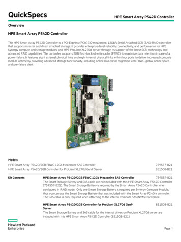
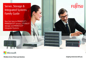
requires high reliability, high request rates, high data transfers, andmedium-to-large capacity.Note:1.4Having virtual drives of different RAID levels, such as RAID0 and RAID 5, in the same drive group is not allowed. Forexample, if an existing RAID 5 virtual drive is created outof partial space in an array, the next virtual drive in thearray has to be R5 only.Configuration ScenariosThere are two main scenarios in which you can use this ServeRAIDcontroller: Low-end, internal SATA configuration: In this configuration, usethe ServeRAID controller as a high-end SATA compatible controllerthat connects to several SATA disks. This type of configuration ismostly for low-end or entry servers. Enclosure management isprovided through out-of-band I2C bus. Side bands of both types ofinternal SAS connectors support the SFF-8485 (SGPIO) interface. Midrange, internal SAS configuration: This configuration is like theinternal SATA configuration, but with high-end disks. This type ofconfiguration is more suitable for low-range to midrange servers.The following figure shows a direct-connect configuration. The Inter-IC(I2C) interface communicates with peripherals. The external memory busprovides a 32-bit memory bus, parity checking, and chip select signalsfor pipelined synchronous burst static random access memory(PSBRAM), nonvolatile static random access memory (NVSRAM), andFlash ROM.Configuration Scenarios1-7
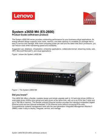
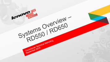
Figure 1.1Example of a SAS Direct-Connect ApplicationSAS/SATA III DeviceSASPCI ExpressRAID ControllerSAS/SATA III DeviceSAS/SATA III Device32-Bit MemoryAddress/DataBusI 2CInterfaceFlash ROM/PSBRAM/NVSRAMI2 CSAS/SATA III DevicePCI Express InterfaceThe following figure shows an example of a ServeRAID controllerconfigured with an expander that is connected to SAS disks, SATA disks,or both.Figure 1.2Example of a ServeRAID Controller Configured with anExpanderPCI Express Interface8SAS RAID ControllerPCI Express to SAS ROCSAS/SATADrivesExpanderSAS/SATA IIIDrives1-8OverviewSAS/SATA IIIDrivesPeripheralBus72-bit DDR/DDR2with ECCInterfaceFlash ROM/NVSRAM/I2C/UARTSRAMSDRAMSRAMExpanderSAS/SATA IIIDrivesSAS/SATA IIIDrives
1.4.1Number of Physical Disks SupportedYour configuration planning for your ServeRAID controller depends inpart on the number of physical disks that you want to use in a RAIDarray. The number of drives in an array determines the RAID levels thatcan be supported by this controller. Only one RAID level can be assignedto each virtual disk. Table 1.1 shows the minimum number and themaximum number of drives required for each RAID level.Table 1.11.5Physical Devices Required for Each RAID LevelRAIDLevelMinimum # ofPhysical DevicesMaximum # ofPhysical Devices013212253326332104325063260632Benefits of the SAS InterfaceSAS is a serial, point-to-point, enterprise-level device interface thatleverages the proven SCSI protocol set. SAS combines the advantagesof SATA, SCSI, and Fibre Channel, and is the future mainstay of theenterprise and high-end workstation storage markets. SAS offers ahigher bandwidth per pin than parallel SCSI, and it improves signal anddata integrity.The SAS interface uses the proven SCSI command set to ensure reliabledata transfers, while providing the connectivity and flexibility ofpoint-to-point serial data transfers. The serial transmission of SCSIcommands eliminates clock-skew challenges. The SAS interfaceprovides improved performance, simplified cabling, smaller connectors,lower pin count, and lower power requirements when compared toparallel SCSI.Benefits of the SAS Interface1-9
The ServeRAID M5110 SAS/SATA controller leverages a commonelectrical and physical connection interface that is compatible with SerialATA technology. The SAS protocols and SATA protocols use a thin,7-wire connector instead of the 68-wire SCSI cable or 26-wire ATA cable.The SAS/SATA III connector and cable are easier to manipulate, allowconnections to smaller devices, and do not inhibit airflow. The point-topoint SATA III architecture eliminates inherent difficulties created by thelegacy ATA master-slave architecture, while maintaining compatibility withexisting ATA firmware.1.5.1PCI Express ArchitecturePCI Express is a local bus system designed to increase data transferswithout slowing down the central processing unit (CPU). You can installyour ServeRAID M5110 controller PCI Express SAS/SATA controller inPCI Express computer systems with a standard bracket type. With thiscontroller in your system, you can connect SCSI devices and SATAdevices over the bus.PCI Express goes beyond the PCI specification in that it is intended asa unifying I/O architecture for various systems: desktops, workstations,mobile, server, communications, and embedded devices.1.5.2Operating System SupportTo check for the latest list of supported operating systems and todownload the drivers for those operating systems, seehttp://www.ibm.com/systems/support/.The ServeRAID M5110 controller uses Fusion-MPT architecture for allmajor operating systems, thinner drivers, and better performance.1-10Overview
1.6Benefits of the ServeRAID M5110 SAS/SATA ControllerThis section provides a summary of the features and the benefits of theServeRAID M5110 SAS/SATA controller. It contains information on SASfeatures, SATA features, PCI performance, integration, usability, andflexibility.The controller offers the following features: PCI Express x8 lane width PCI Express performance up to 8 GT/s (1 GB/s) per lane Two internal connectors Support for RAID levels 0, 1, 5, 10, and 50 in iMR mode Support for RAID levels 0, 1, 5, 6, 10, 50, and 60 in MR modeNote:To use RAID levels 5/50/6/60 with this controller, you needto install a Feature on Demand (FoD) upgrade and/or atransportable memory module (TMM). See Section 1.3.1,“Supported RAID Level Upgrades” for information aboutthese upgrades. Advanced array configuration and management utilities Online RAID level migration Drive migration Drive roaming Media scan No reboot necessary after expansion More than 200 Qtags per array User-specified rebuild rate 32-Kbyte nonvolatile random access memory (NVRAM) for storingRAID system configuration information; the MegaRAID SAS firmwareis stored in flash ROM for easy upgrade.Benefits of the ServeRAID M5110 SAS/SATA Controller1-11
1.6.1SAS FeaturesThe following list describes the SAS features of the ServeRAID M5110controller:1.6.2 Provides eight fully independent PHYs Supports 6.0 Gb/s SAS data transfers per PHY Supports SSP to enable communication with other SAS devices Supports SMP to communicate topology management information Provides a serial, point-to-point, enterprise-level storage interface Simplifies cabling between devices Supports wide ports consisting of 2, 3, or 4 PHYs within a singlequad port Supports narrow ports consisting of a single PHY Transfers data using SCSI information unitsSAS Array LimitationsThis section describes the array limitations of the controller. Theseinclude limitations such as the number of physical disks supported, themaximum number of disks per controller, and the maximum number ofvirtual disks allowed per controller.Table 1.2 lists the array limitations for the ServeRAID M5110 controller.Table 1.2ServeRAID M5110 SAS/SATA Controller ArrayLimitationsSpecificationMaximum virtual disks per controller64Maximum arrays per controller128Maximum virtual disks per array16Maximum physical devices per array32Maximum physical devices per controller1-12ServeRAID M5110SAS/SATA ControllerOverview128Note: Can support up to64 devices, but only16 can be used in aRAID configuration.
Table 1.2ServeRAID M5110 SAS/SATA Controller ArrayLimitationsSpecificationServeRAID M5110SAS/SATA ControllerMaximum hot spares per controller128Maximum spans per virtual disk8Maximum ports2Note:The maximum number of hot spares per array is equal tothe maximum number of physical drives per array.The controller supports 64-bit logical block addressing (LBA), whichmakes it possible to connect a large number of drives to the RAIDcontroller, directly and through expanders. However, the actual numberof drives that you can attach depends on the limits listed in Table 1.2rather than by the actual RAID volume capacity.The maximum numbers in Table 1.2 depend on how many physicaldevices you have connected to the controller. For example, the maximumnumber of arrays per controller is equal to the number of physical diskssupported by the controller up to the limit of 128 arrays per controller. Inaddition, though you can have up to 16 virtual disks per array, and up to128 arrays per controller, there is a limit of 64 virtual disks per controller.1.6.3SATA III FeaturesThe following list describes the SATA III features of the ServeRAIDServeRAID M5110 controller: Supports SATA III data transfers of 6.0 Gb/s Supports STP data transfers of 3.0 Gb/s Provides a serial, point-to-point storage interface Simplifies cabling between devices Eliminates the master-slave construction used in parallel ATA Allows addressing of multiple SATA III targets through an expander Allows multiple initiators to address a single target (in a fail-overconfiguration) through an expander Displays activity and fault indicators for each PHYBenefits of the ServeRAID M5110 SAS/SATA Controller1-13
1.6.4 Supports Port Selector (for dual-port drives) Each port on the controller supports SAS devices, SATA devices, orboth using SSP, SMP, STP, and SATA. SSP enables communicationwith other SAS devices. Enables the controller to communicate with other SATA devices. Supports staggered spin-up Supports hot plugPCI Express PerformanceThe following list describes the PCI Express performance features of theServeRAID M5110 controller: 1.6.5Provides a PCI Express 3.0 interface that:–Supports a dedicated PCI Express bus–Supports x8 lane configuration–Supports transfer rates of up to 8 GT/s (1 GB/s) per lane–Complies with the PCI Express Specification, Revision 3.0 Provides unequaled performance through the Fusion-MPTarchitecture Provides high throughput and low CPU utilization to offload the hostprocessorUsability FeaturesThe following list describes the usability features of the ServeRAIDM5110 controller:1-14 Simplifies cabling with point-to-point, serial architecture Supports smaller, thinner cables that do not restrict airflow Provides drive spin-up sequencing control Provides up to two LED signals for each PHY to indicate link activityand faults Provides an I2C interface for enclosure managementOverview
1.6.6Supports the external SAS Sideband signal SFF-8485 (SGPIO)interfaceFlexibility FeaturesThese features increase the flexibility of the ServeRAID M5110controller:1.6.7 Supports a Flash ROM interface, a nonvolatile static RAM(NVSRAM) interface, and a pipelined synchronous burst SRAM(PSBRAM) interface Offers a flexible programming interface to tune I/O performance Allows mixed connections to SAS targets or SATA III targets Leverages compatible connectors for SAS connections and SATA IIIconnections Allows grouping of up to four PHYs in a single quad port to form awide port Allows programming of the World Wide NameDrive RoamingDrive roaming occurs when the physical disks are changed to differentports on the same controller. When the drives are placed on differentchannels, the controller detects the RAID configuration from theconfiguration data on the drives.Note:In a clustering environment, drive roaming is supportedwithin the same channel only.Configuration data is saved in both the NVRAM on the RAID controllerand on the drives attached to the controller. This action maintains theintegrity of the data on each drive, even if the drives have changed theirtarget ID.Note:If you move a drive that is being rebuilt, the rebuildoperation restarts; it does not resume from where therebuild operation stopped.Benefits of the ServeRAID M5110 SAS/SATA Controller1-15
Follow these steps to use drive roaming:Step 1.Turn off the power to the server and all physical disks,enclosures, and system components. Disconnect the powercords from the system.Step 2.Open the host system by following the instructions in the hostsystem technical documentation.Step 3.Move the drives to different positions on the backplane tochange the targets.Step 4.Determine the SAS target requirements.Step 5.Perform a safety check.a. Make sure that the drives are inserted correctly.b.Close the cabinet of the host system.Step 6.Reconnect the power cords to the system.Step 7.Turn on the power to the system.The controller then detects the RAID configuration from theconfiguration data on the drives.1.6.8Drive MigrationDrive migration is the transfer of a set of drives in an existingconfiguration from one controller to another. The drives must remain onthe same channel and must be reinstalled in the same order as in theoriginal configuration. The controller to which you migrate the drivescannot have an existing configuration.Note:Only whole virtual disks can be migrated automatically;partial virtual disks can be migrated manually.Note:Drive roaming and drive migration cannot be supported atthe same time.Follow these steps to migrate drives:Step 1.1-16OverviewMake sure that you clear the configuration on the system towhich you migrate the drives, to prevent a configuration datamismatch between the drives and the NVRAM.
Note:When you migrate drives, move only the disks that makeup the virtual disk (not all of the physical disks in an array),so that you do not have an NVRAM mismatch error(providing a configuration is on the destination controller).The NVRAM mismatch error appears only if you move allof the drives to the other controller.Step 2.Turn off the power to the server and all physica
B.5.4 European Union EMC Directive Conformance Statement B-6 B.5.5 Germany Class A Statement B-7 B.5.6 Japan VCCI Class A Statement B-8 B.5.7 Korea Communications Commission (KCC) Statement B-9 B.5.8 Russia Electromagnetic Interference (EMI) Class A Statement B-9 B.5.9 People's Republic of China Class A Electronic Emission Statement B-9