Transcription
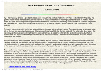
Gamma MatchSome Preliminary Notes on the Gamma MatchL. B. Cebik, W4RNLMy e-mail regularly contains a question that appears in various forms, but has one theme: Why have I not written anything about thegamma match? There are notes at my personal website on various forms of series matching systems and notes on the beta match.These two types of matching systems represent alternatives to the gamma match, especially when the task is to transform the generallylow impedance of a Yagi array up to the value of 50 Ohms, as required by the most common feedlines used in amateur and otherservices.Compared to a gamma match, series and beta matching systems are both simple and precise. Both systems make no alteration to thedriven element, but add networks composed of transmission lines (usually) to the element feedpoint. The beta match does require thatwe initially set the driven element length to arrive at an optimal value of reactance relative to the feedpoint resistance, but the betacomponent is or is equivalent to adding a simple reactance across the feedpoint. The matching systems do not affect the radiationproperties of the element.As a consequence of these conditions, we may calculate the required values for series-matching or beta-matching components veryprecisely. In practice, the key factor affecting field adjustment of the systems is the accuracy of the velocity factor that we use in thecalculations relative to the value that actually applies to the line used. If we know the velocity factor with measured accuracy (in contrastto the values we find in lists and specification sheets), we can often obtain the desired result with no need for further adjustment.These fundamental matching systems are therefore amenable to automated formulation, that is, a utility program or a spreadsheet pagethat will tell us the required values if we input the feedpoint conditions and other values related to the components. In fact, I keep aspreadsheet on hand in my computer for just such calculations. It contains calculations for 1/4-wavelength matching sections, Bramhamtransformations, and Regier series matching calculations. In addition, it allows beta-match calculations and returns results for using eithera shorted transmission-line stub or a solenoid inductor as the most common beta components. However, it also yields open lines andcapacitance values should one choose to lengthen the driven element rather than shortening it. I have also added a page for the matchline and stub system of matching, used with higher-impedance antenna elements. I wrote the pages in Quattro Pro (.qpw), but have alsosaved them in Excel (.xls). You may download the sheet of your choice from the following addresses.Antenna-Match in .XLS format (Excel)file:///E ma.html (1 sur 26)30/04/2008 14:12:11
Gamma MatchAntenna-Match in .QPW format (Quattro Pro)The Gamma DifferenceThe gamma match differs fundamentally from the other matching systems because it alters the physical properties of the driven elementin ways indicated by Fig. 1. First, it adds new wires to the element, giving the element a more complex shape. Second, it changes theelement feedpoint relative to the original element. The simple element uses a feedpoint position that normally is at the center of theelement. The gamma-matched element places the feedpoint on a wire that joins the gamma rod to the main element.One gamma-match advantage to many builders is the fact that the element may now connect directly to the boom. Both series and betamatching systems require driven elements that are insulated and isolated from any conductive support boom. In the era in which socalled "plumber's delight" construction methods ruled amateur Yagi construction, the gamma match equally ruled impedancetransformation for coaxial feedlines. However, connecting the element to the boom changes its electrical length and therefore thefeedpoint impedance prior to creating a gamma match. Therefore, most gamma match users began their calculations or experiments withonly an estimated feedpoint impedance for the pre-matched element. NEC and MININEC antenna-modeling software offer no assistancehere, since these programs only model axial currents (that is, along the element) and thus could not account directly for boom effects.Some builders have come to believe that a gamma match requires a direct connection between the boom and the element center.However, the connection is only an option, not a mandatory condition for the matching system.file:///E ma.html (2 sur 26)30/04/2008 14:12:11
Gamma MatchOne criticism of the gamma match accuses it of displacing the pattern in the direction of the match due to the size of the assembly.Effectively, as some believe, the assembly increases the diameter of the gamma side of the element, and this asymmetry of the drivenelement results in the main lobe's re-aiming. To test this notion, I constructed models of 28-MHz beams with identical reflectors andelement spacing. One beam uses a simple driven element. The other uses a driver with the same overall length, but with a gamma matchassembly (of course, with no boom). The gamma assembly is in the plane of the two elements and projects forward of the driver. Theresults of the test appear in Fig. 2.The slightly lower forward gain of the gamma-matched version of the beam is an artifact of certain limitations of NEC (which we shallreview shortly). The key factor in the overlaid patterns is the degree of lobe displacement, indicated by the lines that I added to the sidesof the lobe. Displacement does indeed occur, but at a level too small for any user ever to notice in operation. The two patterns to the rightshow that the gamma match also has an affect on the free-space side nulls for the array. The simple beam has side nulls that show nolimit. However, the gamma-matched beam has limited side nulls that are a mere 40-dB down from the level of maximum gain. I amfile:///E ma.html (3 sur 26)30/04/2008 14:12:11
Gamma Matchunaware of any operational use of a beam in which one might be able to detect the difference.The modeled test case assumes by its mathematical basis relatively perfect construction of the gamma-match driven element. I have inpast years seen range-generated patterns for gamma-matched beams with a significant displacement of the main forward lobe. It wouldnot be possible to perform a full analysis of such patterns without being able to model currents within the driven element and along theboom--if the elements makes a direct connection to the boom. However, in principle and assuming careful construction, patterndisplacement is not a hindrance to the use of a gamma match.Calculating the Gamma MatchH. H. Washburn, W3MTE, introduced the amateur community to the gamma match in his September, 1949, QST article, "The GammaMatch" (pp. 20-21, 102). D. J. Healey, W3PG, provided the first mathematical analysis of the match in "An Examination of the GammaMatch," QST, April, 1969 (pp.11-15, 57). Healy's treatment, however, required the use of nomographs and a Smith chart.Since these seminal articles, several alternative analyses have appeared in amateur journals. H. F. Tolles, W7ITB, presented a purelymathematical analysis in "How to Design Gamma Matching Networks" in Ham Radio for May, 1973 (pp. 46-55). Because the Tollesequations proved tedious to many gamma designers, R. A. Nelson, WB0IKN, set them into a Basic program in "Basic Gamma Matching,"Ham Radio, January, 1985 (pp. 29-33). ARRL converted Nelson's Apple-Basic program into a version suitable for IBM computers, and alisting appears in The ARRL Antenna Book, 16th Ed. (p. 26-20). In 2000, Dave Leeson, W6NL, corrected portions of the program so thatit more accurately serves as a design vehicle to calculate gamma matches. This program is also available within the HamCalc collectionof Basic utilities edited by George Murphy, VE3ERP. Fig. 3 shows the GW Basic listing for the version of the program distributed byARRL.file:///E ma.html (4 sur 26)30/04/2008 14:12:11
Gamma Matchfile:///E ma.html (5 sur 26)30/04/2008 14:12:11
Gamma MatchSince the work of Tolles and Nelson, two alternative mathematical analyses have appeared. Ron Barker, G4JNH, presented "A NewLook at the Gamma Match" in QEX, May/June, 1999 (pp. 23-31). Barker changes some of the fundamental assumptions about the keyfactors in a gamma match to arrive at his results. Unfortunately, his work is less amenable to easy placement in a Basic utility or aspreadsheet, since the calculations require the solution to simultaneous equations. In contrast, Roger Wheeler, G3MGW, returned to theHealey analysis and converted the graphical techniques back into mathematical methods that allow a straightforward spreadsheet set ofcalculations. Both of these later analyses rely on something that was unavailable to earlier gamma calculations. In most cases, thedetermination of the initial or pre-match driver feedpoint impedance rested on assumption, guesswork, or rudimentary measurement.Measurement became difficult if the builder connected the driver to the boom and did not allow for a feedpoint gap, even if it would laterbe closed. Both Barker and Wheeler require the use of antenna modeling software to determine the pre-match driver impedance. Othermethods exist, for example, the Brian Beezley, K6STI, module in the overall program YO. However, Beazley has never published hisprocedures.The downloadable spreadsheet contains pages for the Healey-Wheeler (HW) and the Tolles-Nelson-Leeson (TNL) methods ofcalculating gamma match rods and series capacitors. Every gamma-match calculating system tries to yield a physical value for the lengthof the gamma rod and a series capacitance value at the feedpoint to leave a pure resistive impedance. The required inputs appear in Fig.4. We need to know the diameters of the main element in the region of the gamma assembly and of the proposed gamma rod, tube, orwire. As well, we must input the center-to-center spacing between the main element and the gamma rod. Ordinarily, the physicaldimensions for the inputs and the outputs are in the same units of measure. The spreadsheets use inches.file:///E ma.html (6 sur 26)30/04/2008 14:12:11
Gamma MatchIn addition, we require two impedance values. One value is for the simple driven element, designated Ra and jXa in Fig. 4. We also needto specify a desired feedpoint impedance, Rf, which is the target resistive impedance that matches the main feedline. For our samples,we shall use 50 Ohms, since it is the most common value that we encounter in amateur radio applications. However, we may apply thegamma match for virtually any reasonable line impedance.Fig. 4 also shows some of the points in the gamma assembly that exhibit derived impedances calculated somewhere within the system.Z1 is the transformed impedance based on the fact that the gamma assembly forms a shorted transmission line stub. (One misguidedcriticism of the Healey system was that it treats the gamma assembly as a folded dipole. Every folded dipole exhibits both radiation andtransmission-line currents. In the calculation of the gamma line, we are concerned with the transmission-line performance of theassembly.) We can derive the characteristic impedance (Zo) of the stub using conventional equations that involve only the physicaldimensions of the line. S is the center-to-center line spacing, and d1 and d2 are the diameters of the gamma rod and the main element,respectively.The TNL system uses more fundamental equations involving havercosines. However, in the typical range of Zo (perhaps 200 to 600Ohms), the differential in results between equations is less than 1% and normally only about 0.1%.file:///E ma.html (7 sur 26)30/04/2008 14:12:11
Gamma MatchWhile we are using only the physical dimensions that we input to the calculation system, we can also calculate a step-up ratio betweenthe original simple-driver impedance and the value shown as Z1 in Fig. 4. The most usually form of the equation again employs the threeinput physical values, S, d1, and d2.Once more, the TNL system uses more fundamental equations, but the differential in result, compared to the more usual engineeringformulation is well under 1%. Both the HW and TNL systems use this equation to calculate the value of Z1 (R1 /- jX1) simply bymultiplying Ra and jXa by the value of r. If the diameters of the main element and the gamma rod are the same, then r 4. If the gammarod is thinner than the main element, then r 4. If the gamma rod is thicker than the main element (an unusual but possible situation),then r 4 but r 1.We may add two side notes here. First, the Barker calculation system does not use the step-up ratio derived from the usual equation.Barker uses the impedance ratio between a simple driver element in isolation (essentially a dipole) to the impedance of the simple driverin service within the beam antenna. Second, at least the HW system does not account for the fact that the impedance undergoes not onlya step-up in value, but also a shift in phase angle when we move from the driver without the gamma assembly to the driver with theassembly. If we model a gamma system and place the feedpoint at the position it would occupy on the pre-gamma driver element, wecan observe the phase-angle shift in the impedance.The HW system calculates the value of Z2, the impedance presumed to exist at the far end of the gamma assembly. If we assume thatthe current distribution is sinusoidal--which is close to correct but not precise--then we may use a standard equation to determine thevalues of R2 and X2.Theta is
NEC and MININEC antenna-modeling software offer no assistance here, since these programs only model axial currents (that is, along the element) and thus could not account directly for boom effects. Some builders have come to believe that a gamma match requires a direct connection between the boom and the element center. However, the connection is only an option, not a mandatory condition for .


