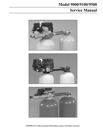
Transcription
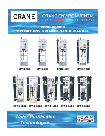
TABLE OF CONTENTSCheck ListIntroductionFig. 1A: OsmosisFig. 1B: EquilibriumFig. 2A: Reverse OsmosisFig. 2B: Reverse Osmosis SystemSpecificationsTable 1: EPRO-150 to 1200 SpecificationsTable 2: EPRO-1500 to 8000 SpecificationsSystem Requirements & Operation GuidelinesTable 3: Feed Water RequirementsStart-UpTable 4: Operation LogFig. 3: EPRO-150 to 1200 DiagramFig. 4: EPRO-1500 to 8000 DiagramAdditional Instructions for EPRO “XP” InstallationFig. 5: EPRO “XP” SystemFig. 6: EPRO- “A” Series SystemFig. 7: EPRO “P” Series SystemFig. 8: EPRO “WM” Series PictureFig. 9: EPRO “XP” Series PictureOperation & MaintenancePump Throttle Valve & Fig. 10: Pump CurvesMembrane CleaningFig. 11: Pressure Vessel ToolsFig. 12: Pressure Vessel DiagramAre Carbon Fines Fouling Your Membranes?Activated Carbon Filter Start-Up ProcedureTroubleshootingTable 5: Troubleshooting TableTable 6: Temperature Correction TableTechnical Field ServicesLimited WarrantyTerms & ConditionsOPTIONAL: ELECTRICAL CONTROL BOXESEPRO 150-8000 O&M ManualRev. 3353738394142-4344-54
Assembly Components ChecklistEPRO 150 - 1200 SYSTEMS:EPRO 1500 – 8000 SYSTEMS:(1)(1)(1)(1)(2)(1)5-Micron Filter Cartridge(2) 10’ X ¾” Black Tube(2) Clamps(2) Hose Connections5-Micron Filter Cartridge10’ X 3/8” Clear Hose10’ X 3/8” Black Tube10’ X1/2” Garden HoseHose ConnectionsEPRO 150-8000O&M MANUALRev.04/03Page 1 of 55
IntroductionReverse osmosis systems fromCrane Environmental produce highquality water from municipal and wellwater.Thehighestqualitycomponents and the latest technologyis used in the production and designof our reverse osmosis systems.What is reverse osmosis?While ordinary filters use a screen toseparate particles from waterstreams, a reverse osmosis systemuses a semi-permeable membraneto separate a high percentage ofdissolved molecules. Only certaintypes of molecules, like water, canpass through the membrane. Othermolecules, like salts, do not passthrough the membrane and are leftbehind.Whatismembrane?asemi-permeableA semi-permeable membrane is verysimilar to your skin. The membraneis made of thin, multi-layered sheetswith microscopic pores that let waterpass through while acting as abarrier to stop dissolved particles likesalt.THE REVERSE OSMOSIS MEMBRANE ELEMENTCONCENTRATE WATER containing salts isrejected by the membrane and does not enterthe product tube. The concentrate water exitsthe side of the element opposite of the feed.RAW WATER FEED enters into membranelayers. Applied pressure forces raw wateracross membrane layers into theproduct tube.Product tubePRODUCT WATER collects in the product tube andcan be output from either end of the membrane element.EPRO 150-8000O&M MANUALRev.04/03Page 2 of 55
How does osmosis and reverseosmosis work?Fig. 1A: OSMOSISMEMBRANEWhen the applied pressure equals theosmotic pressure, the water flowstops. When applied pressureexceeds the osmotic pressure,reverse osmosis will take place. Inreverse osmosis, water passesthrough the membrane to the dilutesolution, leaving behind dissolvedparticles. This process purifies thewater, often reducing total dissolvedsolids content by 99%.FIG. 2A: REVERSE OSMOSISAPPLIED PRESSUREBRINEWATERAs shown in Figure 1A, under normalpressure water will pass from the sideofthemembranewithlowerconcentration to the side with thehigherconcentrationtoreachequilibrium, below.BRINEWATERFIG. 1B: EQUILIBRIUMCrane Environmental systems usesemi-permeable spiral wound, thinOsmotic film membranes to separate andPressure remove dissolved solids, organicmaterial,pyrogens,submicroncolloidal matter, viruses, and bacteriafrom water. Feed water is deliveredunder pressure to the membranes,WATERBRINEwhere reverse osmosis takes place.Water permeates the minute pores ofthe membrane and is delivered aspurified product water. The impuritiesin the water do not pass through themembrane,andareinsteadconcentrated in the reject stream thatOsmotic Pressure is the pressureis flushed to the drain.required to stop water flow and reachequilibrium.EPRO 150-8000O&M MANUALRev.04/03Page 3 of 55
Fig. 2B: Reverse Osmosis SystemEPRO 150-8000O&M MANUALRev.04/03Page 4 of 55
SpecificationsThe basic EPRO unit is designed toproduce purified water at thecapacities indicated by the suffix inthe model number under thefollowing conditions: water temp77ºF (25ºC) and a total dissolvedsolid (TDS) of 500 ppm or less. Forexample, the EPRO-1200 produces1200 gallons per day (GPD) or4,542 liters per day (LPD) of purifiedwater.In addition to the standard modelsthe EPRO models are offered in thefollowing variations:The "P" series EPRO systems arereverse osmosis systems thatdeliver purified water to apressurized storage tank. Theproduct water is typically stored inthe pressurized tank at 20-40 psiand is distributed with tankpressure.The "A” series EPRO systems arereverse osmosis systems that feedpermeatetoa65gallonatmospheric storage tank anddistribute the permeate with asmall dispensing pump.The "XP" series EPRO systemsare modular systems with areverse osmosis unit, a 300-gallonatmospheric storage tank, a liquidlevelcontrol,andarepressurization system. A variety ofstorage tanks and re-pressurizationsystems are available.The "WM" series are reverseosmosis systems suitable for wall-EPRO 150-8000O&M MANUALmounted installation to save floorspace.REJECTION AND RECOVERYThe amount of total dissolved solids(TDS) rejected by the membrane isexpressed as a percentage. Forexample, a 96% rejection ratemeans that 96% of total dissolvedsolids do not pass through themembrane. To calculate the %rejection, use the following formula:NOTE: All TDS figures must beexpressed in the same units, usuallyparts per million (ppm) or milligramsper liter (mg/l).The amount of purified waterrecovered for use is expressed as apercentage of the feed water, and iscalled percent recovery. To calculate% recovery, use the followingformula:NOTE: All Flow Rates must beexpressed in the same units, usuallygallons per minute (gpm).Table 1 on page 6 lists specificationsfor EPRO–150 though 1200 models.Table 2 on page 7 lists specificationsfor EPRO-1500 through 8000.Rev.04/03Page 5 of 55
Table 1:EPRO 150-8000O&M MANUALRev.04/03Page 6 of 55
Table 2:EPRO 150-8000O&M MANUALRev.04/03Page 7 of 55
System Requirements& Operation Guidelines460VAC at 60Hz or 220-380VAC at50 Hz.PLUMBINGThe membranes and high-pressurepumps used on the EPRO systemsrequire a continuous and nonturbulent flow of water to the unit.Minimum feed pressure is 20 PSI.See the tables on pages 6 - 7 todetermine your systems requiredflow.The tubing or piping used fordischarge of the concentrate shouldbe run to an open drain in a free andunrestricted manner.Any restrictions or blockage in thedrain can cause backpressure,which will increase the system’soperating pressure. This can resultin damage to system components.Temperature of the feed water mustnot exceed 113º F (45º C).ELECTRICALAll motors on the EPRO-150 throughthe 1200 are single-phase, open driptype. The standard motors are 60and 50 Hz. The voltage will be either115VAC or 230VAC for the 60motors, or 220VAC for the 50 Hzmotors.The motors on the EPRO-1500through the 8000 are pump/motorcombinations. They are availablesingle-phase: 115VAC or 230VAC at60 Hz or 220VAC at 50 Hz. Thethree phases are available in 230-EPRO 150-8000O&M MANUALEnsure that the electrical circuitsupplying the system is compatiblewith the requirements of the specificEPRO model.Note: We recommend that alicensed electrician install your unit inaccordance with local and nationalelectrical codes.Each EPRO system, excluding theEPRO-4500, the EPRO-8000 and allthree-phase units, is equipped with a10 foot electrical cord. Typical unitsdo not require any additional wiringfor installation. 50 Hz models mayrequire replacement of the standardplug to fit certain receptacles.PRE-FILTRATIONEPRO systems are supplied with aparticulate pre-filter that filters outmost particles over 5 microns in sizebefore the water is pumped throughthe reverse osmosis membrane.Change the cartridge at least everymonth or whenever there is apressure difference of 10% or morebetween the pressure readingsbefore and after the filter, if pressuregauges are installed.CAUTION: If the pre-filter becomesclogged and the water flow to thepumpisreducedorRev.04/03Page 8 of 55
interrupted, cavitation will occur. Thiswill damage the pump.PUMPThe pumps supplied with EPRO-150to 1200 systems are positivedisplacement, rotary vane type. Thepumps supplied with the EPRO-1500to 8000 are multi-stage, centrifugalpumps.EPRO 150-8000O&M MANUALFollow these guidelines for properoperation of both pumps:The pump must NEVER be rundry. Operating the pump withoutsufficient feed water will damagethe pump.ALWAYS feed the pump withfiltered water. The rotary vanetypepumpisespeciallysusceptible to damage fromsediment and debris.Rev.04/03Page 9 of 55
Feed Water RequirementsNothing has a greater effect on aReverse Osmosis System than thefeed water quality. For lastingperformance it is important to supplythe reverse osmosis system with thefeed water quality shown below onTable 3. It is also important to feedthe system the required amount offeed water, shown on Table 1 onpage 6, and Table 2 on page 7.Table 3: Recommended Feed Water QualityHardnessFree ChlorineT.D.S.Turbidity SDIPhIronSilica 1 grain0 ppm 1000 ppm 53-11 0.01 ppm 1 ppmHydrogen SulfideManganeseOrganicsTemperaturePressureNote: The EPRO Tap WaterSystems’ projected output is basedon feed water with a TDS of 500ppm or less at 77 F. Higher TDSand/or lower temperature will reducesystem production.EPRO 150-8000O&M MANUAL0 ppm 0.05 ppm 1 ppm40 F - 80 F8 C - 27 C20 - 60 psiNote: It is very important to meetfeed water requirements. Failure to dso will cause membranes to foul andvoid the warranty.Rev.04/03Page 10 of 55
Start-UpUnless otherwise indicated, theseinstructions cover the basic EPRO150 to 8000 systems as well as the“P”, the “XP”, the “A”, and the “WM”series. When following instructionsplease refer to the appropriatepictures and diagrams depicting yourEPRO system.The Diagram of the EPRO-150 to1200 is FIG. 3 on page 16.The Diagram of the EPRO-1500to 8000 is FIG. 4 on page 17.The Diagram of the “XP” Series isFIG. 5 on page 20.The picture of the “A” Series isFIG. 6 on page 21.The picture of the “P” Series isFIG. 7 on page 21.The picture of the “WM” Series isFIG. 8 on page 22.The Picture of the “XP” Series isFIG. 9 on page 22.INSTALLATIONTheEPROreverseosmosissystems, with the exception of thewall-mounted units, are free standingand require no special installation;however, if placed on an unevenfloor, the system may vibrate. If thisoccurs, place the system on a rubbermat to reduce the vibrations. Forwall-mounted units, attach thesystem to the wall securely(hardware not provided). n are provided on page 18and 19.EPRO 150-8000O&M MANUALCarefully inspect your system beforestart-up. Check all plumbing andelectrical connections. Connectionsmay have loosened during shipment.The following hoses are shippedloose to assist in installation:A 10’ clear braided inlet hose.A 10’ poly tube permeatehose.A 10’ poly tube concentratehose.START-UPThe 5-micron filter cartridge isshipped separate from it’s housing.Steps 1-6 cover installation of thisfilter.1. Locate the 5-micron pre-filterhousing (FIG. 4 or pointer 1 on thepicture or diagram of your EPROsystem). Unscrew the filterhousing. If necessary, use aspanner wrench (not provided).Note: Water may spill from the unitwhen the housing is removed. Placea bucket below the housing to catchthe water.2. Remove the rubber O-ring fromthe groove located below thethreaded part of the housing.Remove any dirt and old lubricantwith a clean rag.3. Inspect the inside of the housingfor debris and rinse with water, ifnecessary.Rev.04/03Page 11 of 55
4. Lubricate the rubber O-ring with afood grade O-ring lubricant andplace in the groove of the housing.5. Locate the 5 micron pre-filtercartridge provided with thepackage. Remove the wrappingfrom the cartridge and insert it intothe housing. Screw the housingonto the cap hand tight.6. Locate the feed water inlet on thepre-filter housing (pointer 2 on thedrawing or picture of yoursystem).7. Attach the provided inlet hose tothefeedwaterinlet,orpermanently plumb the feed waterpiping or tubing to the inlet.ALWAYS maintain a smooth andsufficient flow of feed water duringoperation.8. Locate the permeate outlet.(Pointer 3 on the picture ordiagram of your EPRO system)9. Attach the permeate hose to thepermeate outlet. (Note: the “P”series systems have a checkvalve installed in the permeateline between the membrane andthe bladder tank). Make sure thatpermeate water can flow freelyand that there is no backpressure.permeate will normally be 1-2 pointslower than the feed water pH. A pHof 6.5 or lower can be veryaggressive to some plumbingmaterials, such as copper piping.10. Locate the concentrate (waste)outlet (pointer 4 on the picture ordiagram of your EPRO system).For the “P” series systems: Theconcentrate outlet is locatedbehind the control panel. Unscrewthe top panel. Locate theconcentrate outlet on the drainside of the concentrate controlvalve (see pointer 4 on FIG. 3 and4).11. Attach, the clear drain hose to theconcentrate outlet.12. Run the concentrate line to drain.Water must be allowed to runfreely, without any restrictions orblockage in the drain line.Make sure that NO backpressureexists on the concentrate line.13. Ensure that the electrical powerrequirements of the EPRO systemmatch your electrical powersupply.Backpressure can cause damage tothe membrane.CAUTION:Consult a qualifiedelectrician for proper start-up of yourthree-phase motor. When connectinga three-phase motor, always checkfor proper direction of rotation.Incorrect rotation will damage thepump and void the warranty.CAUTION:the plumbing in thepermeate line can contaminate thehigh quality water produced by theEPRO system; ensure that thecomponents are compatible with theapplication. The pH of the RO14. EPRO systems are typicallycontrolled with a liquid level switchin a storage tank. The liquid levelswitch turns the EPRO system onwhen the water level in the tankdrops, and off when the tank isEPRO 150-8000O&M MANUALRev.04/03Page 12 of 55
full. If your RO system is equippedwith an electrical control box, thelevel control is connected to thelevel control connections in thecontrolbox(seeelectricaldiagrams provided). If your ROsystem is not equipped with acontrol box, plug the level controlinto your power outlet, then plugthe RO power cord into the levelcontrol.DO NOT exceed the level control’spower rating.Liquid level switches can be obtainedfrom Crane Environmental or aplumbing supplier. A liquid levelswitch is standard with the "XP"system.If a liquid level switch is to be used,install it at this time and turn thepower to the EPRO system on.Otherwise, turn the system on byplugging in the power cord. Allow thesystem to run for about three to fiveminutes with the concentrate controlvalve fully open to purge air from thesystem.15. IMPORTANT:TheEPROmachine contains a preservativesolution that can be harmful ifdigested. Discard the product andconcentrate water from the firstone (1) hour of operation. Turn theconcentrate control valve until theconcentratepressuregaugeindicates a pressure of 50 psi.Flush the machine at 50 psi for one(1) hour to remove the preservativefrom the system. Check for leaks.All Crane Environmental reverseosmosis systems are fully testedprior to shipment, but leaks mayoccur due to shipping.EPRO 150-8000O&M MANUAL16. AFTER the preservative solutionhas been flushed out of thesystem, connect the permeate lineto the point-of-use. Make sure nobackpressureexistsonthepermeate line.17. Locate the concentrate controlvalve (Pointer 5 on Fig. 3 and 4)and the concentrate pressuregauge (Pointer 6 on Fig. 3 and 4).18. Turn the concentrate control valveuntil the designated permeate flowis acquired. For example anEPRO-150 should be adjusted untilit produces about 150 GPD or 0.10GPM of permeate flow. Theconcentrate pressure will increaseas the concentrate control valve isclosed. The exact operatingpressure may vary depending onthe temperature and TDS of yourfeed water. It may be necessary tore-adjust the system if there is amajor change in feed watertemperature and/or TDS.WARNING:Never exceed themaximum pressure rating of yourmembrane or pressure vessel.NOTE:The EPRO 1500-8000Reverse Osmosis Systems areequipped with a pump dischargethrottle valve. This valve is used toadjust the Reverse Osmosis systemto the desired recovery. Forinformation about the pump throttlevalve, refer to page 25.Rev.04/03Page 13 of 55
Feed water enters the systemthrough an automatic shut-off valve.Ensure that the valve opens whenthe system turns on, allowing waterflow through the system, and closeswhen the system turns off, stoppingEPRO 150-8000O&M MANUALwater flow through the system. Thiswill save water and preventpremature fouling of the reverseosmosis membrane.Complete Table 4: OperationLog on page 15 with yourStart-Up data and return toCraneEnvironmentaltovalidateyourreverseosmosis system’s warranty.Save a copy of your start-upinformation for your records.We recommend that youmaintain your Operation Log foryour system.Rev.04/03Page 14 of 55
Table 4: Operation LogCOMPANY:LOCATION:WEEK OF:MACHINE SERIAL #:DATEDATE OF START-UPDATE OF LAST CLEANING:CLEANING FORMULATION:TIMEHOURS OF OPERATIONCARTRIDGE FILTER INLET PRESSURE (psi)DIFFERENTIAL PRESSURE (psi)PERMEATE PRESSURE (psi)FEED PRESSURE (psi)CONCENTRATE PRESSURE (psi)DIFFERENTIAL PRESSURE (psi)PUMP DISCHARGE PRESSURE (psi)PERMEATE FLOW (GPM)CONCENTRATE FLOW (GPM)FEED FLOW (GPM)RECOVERY (%)FEED TEMPERATURE (oF)FEED CONDUCTIVITY (mg/L)PERMEATE CONDUCTIVITY (mg/L)REJECTION (%)FEED pHPERMEATE pHSCALE INHIBITOR FEED (PPM)ACID FEED (PPM)SODIUM BISULFITE FEED (PPM)FEED WATER: IRON (mg/L)FREE CHLORINE (mg/L)HARDNESS (PPM CaCO3)TURBIDITY (NTU)EPRO 150-8000O&M MANUALRev.04/03Page 15 of 55
FIG. 3: EPRO-150 to 1200 Diagram1. PRE-FILTER HOUSING2. FEED WATER INLET3. PERMEATE OUTLET4. CONCENTRATE OUTLET5. CONCENTRATE CONTROL VALVE6. CONCENTRATE PPRESSURE VALVE7.* CONCENTRATE FLOW METER8.* PERMEATE FLOW METER9.* WASTE RECYCLE VALVE10. INLET SOLENOID VALVE11. PUMP12. MOTOR13. PRESSURE VESSEL (SEE BELOW)14.* CONTROL BOX (LOW PRESSUREOPTIONS / FLOAT SWITCH* INDICATES THAT THE ITEM IS OPTIONAL.NOTE: THE SIZE AND NUMBER OF THE PRESSURE VESSLES VARIES ACCORDING TOEPRO MODEL.EPRO 150-8000O&M MANUALRev.04/03Page 16 of 55
FIG. 4: EPRO-1500 to 8000 Diagram1. PRE-FILTER HOUSING2. FEED WATER INLET3. PERMEATE OUTLET4. CONCENTRATE OUTLET5. CONCENTRATE CONTROL VALVE6. CONCENTRATE PPRESSURE VALVE7.* CONCENTRATE FLOW METER8.* PERMEATE FLOW METER9.* WASTE RECYCLE VALVE10. INLET SOLENOID VALVE11. PUMP12. MOTOR13. PRESSURE VESSEL (SEE BELOW)14.* CONTROL BOX (LOW PRESSUREOPTIONS / FLOAT SWITCH* INDICATES THAT THE ITEM IS OPTIONAL.NOTE: THE SIZE AND NUMBER OF THE PRESSURE VESSLES VARIES ACCORDING TOEPRO MODEL.EPRO 150-8000O&M MANUALRev.04/03Page 17 of 55
Additional Instructionsfor “XP” Installation“XP” SYSTEM COMPONENTCHECKLIST:1)2)3)4)5)RO systemAtmospheric TankRe-pressurization SystemSuction Tube AssemblyLiquid Level Control (Float Switch)1.Storage Tank Preparation:Plumb the RO permeate line to thestorage tank. A white nylon compressionfitting is supplied with the permeate line.Fasten this fitting to the storage tank inthe hole in top of the tank by:(a) Removing the compression fitting andhex nut from one side,(b) Sliding the threads through the hole inthe tank, and(c) Reattaching and tightening the hexnut from inside the tank.Attach the permeate line to thecompression fitting on the RO machine.Attach the other end of the permeate lineto the newly installed compression fittingon the storage tank.2.Connecttheatmosphericstorage tank to the re-pressurizationsystem:Use the suction tube assembly supplied.Some connections on the suction tubeassembly are not glued to facilitateassembly. Remove the male adaptor thatis near the ball valve on the suction tubeassembly. Thread the male adaptor intoEPRO 150-8000O&M MANUALthe bulkhead fitting at the bottom of thestorage tank. Use Teflon tape to preventleaking.Plumb from the storage tank suction tubeto the inlet (nose cone) on the repressurization pump. Make sure that thecheck valve is pointing in the direction ofthe water flow.3.Connect the line from the repressurization system to the point ofuse:This will be from the cross fitting on thebottom of the pressure tank piping.4a.Level Control (Solo Float,standard):The cord from the solo float must besecured inside the storage tank at a pivotpoint between the desired high and lowlevel. Adjust the differential between highor low level by changing the length of thecord between the pivot and float. Adjustthe high and low levels by moving thepivot point up or down.4b.Level Control (Ball and Rod,optional on XP system):Mount the level control onto the storagetank through diagonal holes using theattached stainless steel fasteners.Remove the setscrew from the brasscollar on the float switch shaft. Make asingle vertical slit in the 1” diameter floatarm screen. From the inside of the tank,slip the float arm through the slit thenattach the float arm to the brass collar.Slide the brass collar onto the shaft ofthe float switch and tighten securelyusing the float rod as the setscrew.Attach the float ball to the unattachedend of the float arm. Adjust the float armso that the top of the float ball doesn'tRev.04/03Page 18 of 55
rise above the lowest point of the bottomof the switch. Refer to Figure 5.7.Priming:After the storage tank is filled, the repressurization system must be primedand started. Prime the pump by removingthe pressure gauge and pouring waterinto the pump. Reinstall the pressuregauge in the fitting. Move the lever on theside of the pressure switch to the“START” position. Open the drain valveslightly to allow air to escape during startup. This is located at the bottom of thepressure tank. Close after start up. Afterthe unit is primed, and the unit begins topump, hold the lever on "START' untilpressure reaches 30 psi. Operation fromthis point on is automatic. If the pumpdoesn't build pressure within 20 seconds,repeat the priming sequence. Failure toproperly prime the pump can causedamage that is not covered under thewarranty.5.Electrical Connection:Make sure water is available to thereverse osmosis system before makingthis connection because this will start theRO machine. Insert the EPRO systemmale plug into the float switch femaleconnector. Insert the float switch maleplug to a power source. This will start theRO system when the float switch is in thedown position.NOTE: Male plugs are supplied with 10'of lead. Extension cords are notrecommended. If a longer wire run isrequired, please retain a qualifiedelectrician.6.Re-pressurization System StartUp:With an air pressure gauge, insure thatthe bladder tank pre-charge is set 2 psibelow the cut in pressure (see examplebelow).Example:Operating Pressure RangeBladder Tank Pre-charge20-40 PSI18 PSIEPRO 150-8000Connect the re-pressurization pumppower plug to a power source.30-50 PSI28 PSIO&M MANUALRev.04/03Page 19 of 55
Fig. 5:EPRO “XP” System1.2.3.4.RO INLETPERMEATE LINEINLET SOLENOID & VALVELEAD from RO MOTOR ORCONTROL BOX TO FLOATSWITCH5. LEAD to ELECTRIC POWERSOURCE6. FLOAT SWITCH7. FLOAT BALL (2)EPRO 150-8000O&M MANUAL8. ATMOSPHERIC STORAGETANK9. CHECK VALVE10. SUCTION LINE11. PRESSURE SWITCH12. PUMP & MOTOR13. PRESSURE SWITCH14. POINT OF USE15. PRESSURE GAUGERev.04/03Page 20 of 55
Fig. 6: EPRO “A” SeriesFig. 7: EPRO “P” SeriesEPRO 150-8000O&M MANUALRev.04/03Page 21 of 55
Fig. 8: EPRO “WM” SeriesFig. 9: EPRO “XP” SeriesEPRO 150-8000O&M MANUALRev.04/03Page 22 of 55
Operation & MaintenanceReverseosmosiscausestheconcentration of impurities in theconcentrate stream to increase. Theimpurities may precipitate (come outof solution) when their concentrationreachessaturationlevels.Precipitation can scale or foulmembranesandmustbeprevented. Check your feed waterchemistry. Pre-treat the water and/orreduce the system recovery asrequired. If necessary, consult with aCraneEnvironmentalservicerepresentative for TIONALPrefilter Pressure Gauges:These gauges measure the feedwater pressure when it enters andexits the pre-filter housing. Apressure differential of 10 % or moreon the two pressure readingsindicates that the pre-filter needs tobe replaced. For example, if inletpressure is 40 psi, the filter shouldbe changed when the outlet pressureis 36 psi or below.Product Water (Permeate)Flow Meter (pointer 8 on FIG. 3and 4) and Waste Water(Concentrate)FlowMeter(pointer 7 on FIG. 3 and 4):These flow meters indicate the flowrates of permeate and concentratewater. The measurements, whenadded together, also indicate thefeed water flow rate, if the system isnot equipped with waste recycle.Waste Recycle Valve (pointer9 on FIG. 3 and 4):EPRO 150-8000O&M MANUALThis valve allows you to recyclesome of the concentrate water backto the feed of the pump. This willincrease the recovery of the EPROsystem. An optional waste recycleflow meter allows you to measurehow much concentrate is recycled.THE AMOUNT OF WASTE WATERRECYCLED IS LIMITED BY THETDS OF THE FEED WATER.CAUTION: Excessiverecyclingmay cause premature fouling orscaling of the membrane.Low Pressure Reverse ActionSwitch (normally offered onthe EPRO-150 to 1200):The reverse action switch shuts offthe EPRO system when the feedwater pressure drops too low for thesystem to function properly. Thisprevents damage to the pump. Thesystem restarts automatically whenpressure is restored. If you notice thepressure fluctuating, and the systemcycling off and on repeatedly, turnthe system off and ensure thatproper feed flow and pressure areavailable to the system.LowPressureShut-OffControl Box (normally offeredon the EPRO-1500 to 8000):This option consists of an electricalcontrol box with a low-pressureprotection circuit, level controlconnections,pre-treatlockoutconnections, and an on/off switch.The low-pressure shut-off switch canbe ordered with manual or automaticreset.Automatic Fast Flush:Rev.04/03Page 23 of 55
The automatic fast flush optionbypasses the concentrate controlvalve, reducing the concentratepressure and increasing the flow offeed water across the membrane.The fast flush removes foulants thatmay have attached to the surface ofthe membrane. By removing thesefoulants before they crystallize onthe surface of the membrane, thesystem can operate longer withoutcleaningand/orreplacingmembranes. Crane Environmentalrecommends the use of theautomatic fast flush in severalinstances:1. Wheninjectingantiscalantchemicals. These chemicals keepscaling ions in solution up to ahigher concentration so the ionsdon’t precipitate, and scale themembrane. If the solubilityconcentration is exceeded, theions may precipitate and scale themembrane.2. For feed water with a high scalingpotential (hard water) in addition toautomatic fast flush, pre-treat thewater with an antiscalant or asoftener. Do not use the automaticfast flush instead of pretreatment.3. Where minimal maintenance isimportant, an auto flush canincrease the time betweenmembrane cleaning.5. For high recovery applications(use of a recycle valve), considerusing auto flush.6. For systems that may remaininoperative for long periods oftime, a fast flush should beinstalled. The automatic fast flushwill not operate if the electricalpower is removed from thesystem.The auto flush option includes atimer with two adjustable settingsthat regulate its operation. One timersetting allows you to set the intervalbetween flushing, and the other timersetting allows you to set the length ofthe flush time. The timer is preset atthe factory to initiate a 5-minute flushevery 10 hours. This is based on thetime the system has electrical powerapplied.In the fast flush conditions the waterflushes across the membrane in thesame direction as water flows innormal operation; this is not a“backwash” flow.NOTE:Some permeate will beproduced during the automatic fastflush; therefore, an overflow for thepermeatestoragetankisrecommended.4. For high TDS (total dissolvedsolids) applications where theTDS exceeds 500 ppm, considerinstalling an auto flush.EPRO 150-8000O&M MANUALRev.04/03Page 24 of 55
Pump Throttle Valve (pointer 15 on Fig. 4)This valve is installed as a standardfeature on all EPRO – 1500 throughEPRO – 8000 reverse osmosissystems. It provides an adjustmentfor pump flow, which will vary as therequired system pressure changes.To understand this concept, pleaserefer to the pump curves in figure 10.Note that with a centrifugal pump,the pump flow decreases as theoperating pressure increases.Example:PRESSURE120 psi150 psi180 psi1 HP10.5 gpm8 gpm4 gpm1.5 HP12 gpm10.5 gpm8 gpmAs the feed water temperaturedecreases, and/or the feed waterTDS increases, the system willrequire a higher operating pressureto produce the specified permeateflow. An EPRO-1500 installed inFlorida may provide the specifiedpermeate flow of 1 gpm at 130 psi;however, the same EPRO-1500installed in Maine – much colderfeed water – may require 190psi toproduce this same amount ofpermeate. The Florida system wouldhave higher concentrate flow to drainbecause of the lower operatingpressure, which would result in poorsystem recovery.Figure 10: Pump CurvesThe pump throttle valve can beadjusted to the desired systemrecovery for applications that fit thesystem specifications.EPRO 150-8000O&M MANUALRev.04/03Page 25 of 55
EPRO 1500 – 3000 50 HZEPRO 1500 – 3000 60 HZEPRO 4500 – 6000 50 HZEPRO 4500 – 6000 60 HZEPRO 150-8000O&M MANUALRev.04/03Page 26 of 55
Membrane CleaningPeriodiccleaningofthemembrane(s) can improve systemperformance. In normal operation,mineral
EPRO 150-8000 O&M MANUAL Rev.04/03 Page 5 of 55 Specifications The basic EPRO unit is designed to produce purified water at the capacities indicated by the suffix in the model number under the following conditions: water temp 77ºF (25ºC) and a total dissolved solid (TDS) of 500 ppm or less. For example, the EPRO-1200 produces