Transcription
ProductFolderSample &BuyTechnicalDocumentsSupport &CommunityTools &SoftwareSN74LVC1G00SCES212AB – APRIL 1999 – REVISED APRIL 2014SN74LVC1G00 Single 2-Input Positive-NAND Gate1 Features 1 3 Description2Available in the Ultra Small 0.64-mmPackage (DPW) With 0.5-mm PitchSupports 5-V VCC OperationInputs Accept Voltages to 5.5 VProvides Down Translation to VCCMax tpd of 3.8 ns at 3.3 VLow Power Consumption, 10-μA Max ICC 24-mA Output Drive at 3.3 VIoff Supports Live Insertion, Partial-Power-DownMode, and Back Drive ProtectionLatch-Up Performance Exceeds 100 mAPer JESD 78, Class IIESD Protection Exceeds JESD 22– 2000-V Human-Body Model (A114-A)– 1000-V Charged-Device Model (C101)2 Applications AV ReceiverAudio Dock: PortableBlu-ray Player and Home TheaterEmbedded PCMP3 Player/Recorder (Portable Audio)Personal Digital Assistant (PDA)Power: Telecom/Server AC/DC Supply: SingleController: Analog and DigitalSolid State Drive (SSD): Client and EnterpriseTV: LCD/Digital and High-Definition (HDTV)Tablet: EnterpriseVideo Analytics: ServerWireless Headset, Keyboard, and MouseThis single 2-input positive-NAND gate is designedfor 1.65-V to 5.5-V VCC operation.The SN74LVC1G00 performs the Boolean functionY A B or Y A B in positive logic.The CMOS device has high output drive whilemaintaining low static power dissipation over a broadVCC operating range.The SN74LVC1G00 is available in a variety ofpackages, including the ultra-small DPW packagewith a body size of 0.8 mm 0.8 mm.white spacewhite spaceDevice Information(1)DEVICE NAMESN74LVC1G00PACKAGEBODY SIZESOT-23 (5)2.9mm 1.6mmSC70 (5)2.0mm 1.25mmX2SON (4)0.8mm 0.8mmSON (6)1.45mm 1.0mmDSBGA (5)1.41mm 0.91mm(1) For all available packages, see the orderable addendum atthe end of the datasheet.4 Simplified Schematic1An IMPORTANT NOTICE at the end of this data sheet addresses availability, warranty, changes, use in safety-critical applications,intellectual property matters and other important disclaimers. PRODUCTION DATA.
SN74LVC1G00SCES212AB – APRIL 1999 – REVISED APRIL 2014www.ti.comTable of Contents12345678Features .Applications .Description .Simplified Schematic.Revision History.Pin Configuration and Functions 7.103344555566Absolute Maximum Ratings .Handling Ratings.Recommended Operating Conditions .Thermal Information .Electrical Characteristics.Switching Characteristics, CL 15 pF .Switching Characteristics, –40 C to 85 C.Switching Characteristics, –40 C to 125 C.Operating Characteristics.Typical Characteristics .Parameter Measurement Information . 79Detailed Description . 99.19.29.39.4Overview .Functional Block Diagram .Feature Description.Device Functional Modes.999910 Application and Implementation. 1010.1 Application Information. 1010.2 Typical Application . 1011 Power Supply Recommendations . 1112 Layout. 1112.1 Layout Guidelines . 1112.2 Layout Example . 1113 Device and Documentation Support . 1213.1 Trademarks . 1213.2 Electrostatic Discharge Caution . 1213.3 Glossary . 1214 Mechanical, Packaging, and OrderableInformation . 125 Revision HistoryChanges from Revision AA (March 2014) to Revision ABPage Added Pin Functions table. . 3 Updated Handling Ratings table. . 3 Added Thermal Information table. . 4 Added Typical Characteristics. . 6 Added Detailed Description section. . 9 Added Application and Implementation section. . 10 Added Power Supply Recommendations section. . 11 Added Layout section. . 11Changes from Revision Z (November 2014) to Revision AAPage Added Applications section. . 1 Added Device Information table. . 1 Added Tstg to Handling Ratings table. . 3Changes from Revision Y (September 2013) to Revision Z Changed document Features. . 1Changes from Revision X (November 2012) to Revision Y 2PagePageExtended operating temperature from 85 C to 125 C. . 4Submit Documentation FeedbackCopyright 1999–2014, Texas Instruments IncorporatedProduct Folder Links: SN74LVC1G00
SN74LVC1G00www.ti.comSCES212AB – APRIL 1999 – REVISED APRIL 20146 Pin Configuration and FunctionsA1B2GND3AVCC5DRL PACKAGE(TOP VIEW)DCK PACKAGE(TOP VIEW)DBV PACKAGE(TOP CBGND2534NCYY4Y4DPW PACKAGE(TOP VIEW)YZP PACKAGE(BOTTOM VIEW)Y4DSF PACKAGE(TOP VIEW)DRY PACKAGE(TOP VIEW)GNDNC – No internal connectionSee mechanical drawings for dimensions.3 4B2A1 5YGNDBA15342VCCYVCCPin FunctionsPINDESCRIPTIONNAMEDBV, DCK,DRL, YZPDRY, 65Power pinNC5Not connected7 Specifications7.1 Absolute Maximum Ratings (1)over operating free-air temperature range (unless otherwise noted)MINMAXVCCSupply voltage range–0.56.5VVIInput voltage range–0.56.5VVOVoltage range applied to any output in the high-impedance or power-off state (2)–0.56.5VVOVoltage range applied to any output in the high or low state (2) (3)–0.5VCC 0.5VIIKInput clamp currentVI 0–50mAIOKOutput clamp currentVO 0–50mAIOContinuous output current 50mA 100mAContinuous current through VCC or GND(1)(2)(3)UNITStresses beyond those listed under Absolute Maximum Ratings may cause permanent damage to the device. These are stress ratingsonly, and functional operation of the device at these or any other conditions beyond those indicated under Recommended OperatingConditions is not implied. Exposure to absolute-maximum-rated conditions for extended periods may affect device reliability.The input and output negative-voltage ratings may be exceeded if the input and output current ratings are observed.The value of VCC is provided in the Recommended Operating Conditions table.7.2 Handling RatingsMINTstgStorage temperature rangeV(ESD)(1)(2)Electrostatic dischargeMAX–65150Human body model (HBM), per ANSI/ESDA/JEDEC JS-001, allpins (1)02000Charged device model (CDM), per JEDEC specificationJESD22-C101, all pins (2)01000UNIT CVJEDEC document JEP155 states that 500-V HBM allows safe manufacturing with a standard ESD control process.JEDEC document JEP157 states that 250-V CDM allows safe manufacturing with a standard ESD control process.Submit Documentation FeedbackCopyright 1999–2014, Texas Instruments IncorporatedProduct Folder Links: SN74LVC1G003
SN74LVC1G00SCES212AB – APRIL 1999 – REVISED APRIL 2014www.ti.com7.3 Recommended Operating Conditions (1)VCCOperatingSupply voltageMAX5.5Data retention onlyV0.65 VCCVCC 2.3 V to 2.7 VHigh-level input voltageUNIT1.5VCC 1.65 V to 1.95 VVIHMIN1.651.7VCC 3 V to 3.6 VV2VCC 4.5 V to 5.5 V0.7 VCCVCC 1.65 V to 1.95 V0.35 VCCVCC 2.3 V to 2.7 V0.7VCC 3 V to 3.6 V0.8VILLow-level input voltageVIInput voltage05.5VVOOutput voltage0VCCVVCC 4.5 V to 5.5 V0.3 VCCVCC 1.65 V–4VCC 2.3 VIOHHigh-level output current–8–16VCC 3 VLow-level output currentΔt/Δv–32VCC 1.65 V4VCC 2.3 V816VCC 3 VInput transition rise or fall rate(1)mA24VCC 4.5 V32VCC 1.8 V 0.15 V, 2.5 V 0.2 V20VCC 3.3 V 0.3 V10VCC 5 V 0.5 VTAmA–24VCC 4.5 VIOLVns/V5Operating free-air temperature–40125 CAll unused inputs of the device must be held at VCC or GND to ensure proper device operation. Refer to the TI application report,Implications of Slow or Floating CMOS Inputs, literature number SCBA004.7.4 Thermal InformationSN74LVC1G00THERMAL METRIC (1)DBVDCKDRLDRYYZPDPW5 PINS5 PINS5 PINS6 PINS5 PINS4 PINSRθJAJunction-to-ambient thermal case (top) thermal resistance164937827754215RθJBJunction-to-board thermal resistance62657827151294ψJTJunction-to-top characterization parameter4421084141ψJBJunction-to-board characterization parameter62647727150294RθJC(bot)Junction-to-case (bottom) thermal resistance–––––250(1)4UNIT C/WFor more information about traditional and new thermal metrics, see the IC Package Thermal Metrics application report, SPRA953.Submit Documentation FeedbackCopyright 1999–2014, Texas Instruments IncorporatedProduct Folder Links: SN74LVC1G00
SN74LVC1G00www.ti.comSCES212AB – APRIL 1999 – REVISED APRIL 20147.5 Electrical Characteristicsover recommended operating free-air temperature range (unless otherwise noted)PARAMETERTEST CONDITIONSVCCTYP (1)MINIOH –100 μAVOH1.65 V to 5.5 VVCC – 0.1VCC – 0.11.21.2IOH –8 mA2.3 V1.91.92.42.42.32.33VIOL 100 μA1.65 V to 5.5 V0.10.1IOL 4 mA1.65 V0.450.45IOL 8 mA2.3 V0.30.33.80.40.40.550.550.550.550 to 5.5 V 5 5μA3VIOL 32 mA4.5 VVI 5.5 V or GNDIoffVI or VO 5.5 VICCVI 5.5 V or GNDΔICCOne input at VCC – 0.6 V,Other inputs at VCC or GNDCiVI VCC or GND(1)V4.5 VIOL 16 mA3.8UNITMAXIOH –32 mAIOL 24 mAIITYP (1)MIN1.65 VIOH –24 mAA or BinputsMAXIOH –4 mAIOH –16 mAVOLRECOMMENDED–40 C to 125 C–40 C to 85 CIO 0V0 10 10μA1.65 V to 5.5 V1010μA3 V to 5.5 V500500μA3.3 V44pFAll typical values are at VCC 3.3 V, TA 25 C.7.6 Switching Characteristics, CL 15 pFover recommended operating free-air temperature range (unless otherwise noted) (see Figure 3)–40 C to 85 CPARAMETERFROM(INPUT)TO(OUTPUT)tpdA or BYVCC 1.8 V 0.15 VVCC 2.5 V 0.2 VVCC 3.3 V 0.3 VVCC 5 V 0.5 3.4ns7.7 Switching Characteristics, –40 C to 85 Cover recommended operating free-air temperature range, CL 30 pF or 50 pF (unless otherwise noted) (see Figure 4)–40 C to 85 CPARAMETERtpdFROM(INPUT)A or BTO(OUTPUT)YVCC 1.8 V 0.15 VVCC 2.5 V 0.2 VVCC 3.3 V 0.3 VVCC 5 V 0.5 VUNITMINMAXMINMAXMINMAXMINMAX3.191.35.514.714ns7.8 Switching Characteristics, –40 C to 125 Cover recommended operating free-air temperature range, CL 30 pF or 50 pF (unless otherwise noted) (see Figure 4)RECOMMENDED–40 C to 125 CPARAMETERFROM(INPUT)TO(OUTPUT)MINtpdA or BY3.1tpdAY2VCC 1.8 V 0.15 VVCC 2.5 V 0.2 VVCC 3.3 V 0.3 VVCC 5 V 0.5 .30.73.1nsSubmit Documentation FeedbackCopyright 1999–2014, Texas Instruments IncorporatedProduct Folder Links: SN74LVC1G00UNIT5
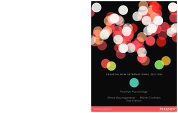
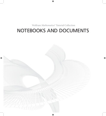
SN74LVC1G00SCES212AB – APRIL 1999 – REVISED APRIL 2014www.ti.com7.9 Operating CharacteristicsTA 25 CCpdPARAMETERTESTCONDITIONSVCC 1.8 VVCC 2.5 VVCC 3.3 VVCC 5 VTYPTYPTYPTYPPower dissipation capacitancef 10 MHz22222325UNITpF7.10 Typical Characteristics86TPD756TPD - nsTPD - ns435432211TPD0-1000-50050Temperature - C10015001D001Figure 1. TPD Across Temperature at 3.3V Vcc6Submit Documentation Feedback23Vcc - V456D002Figure 2. TPD Across Vcc at 25 CCopyright 1999–2014, Texas Instruments IncorporatedProduct Folder Links: SN74LVC1G00
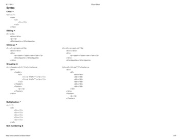
SN74LVC1G00www.ti.comSCES212AB – APRIL 1999 – REVISED APRIL 20148 Parameter Measurement InformationVLOADS1RLFrom OutputUnder TestOpenTESTGNDCL(see Note A)S1OpenVLOADtPLH/tPHLtPLZ/tPZLtPHZ/tPZHRLGNDLOAD CIRCUITINPUTSVCC1.8 V 0.15 V2.5 V 0.2 V3.3 V 0.3 V5 V 0.5 VVItr/tfVCCVCC3VVCC 2 ns 2 ns 2.5 ns 2.5 nsVMVLOADCLRLVDVCC/2VCC/21.5 VVCC/22 VCC2 VCC6V2 VCC15 pF15 pF15 pF15 pF1 MW1 MW1 MW1 MW0.15 V0.15 V0.3 V0.3 VVITiming InputVM0VtWtsuVIInputVMVMthVIData InputVMVM0V0VVOLTAGE WAVEFORMSPULSE DURATIONVOLTAGE WAVEFORMSSETUP AND HOLD OutputWaveform 1S1 at VLOAD(see Note ntrolVMVOLVOLTAGE WAVEFORMSPROPAGATION DELAY TIMESINVERTING AND NONINVERTING OUTPUTSOutputWaveform 2S1 at GND(see Note B)VOL VDVOLtPHZVMVOH – VDVOH»0 VVOLTAGE WAVEFORMSENABLE AND DISABLE TIMESLOW- AND HIGH-LEVEL ENABLINGNOTES: A. CL includes probe and jig capacitance.B. Waveform 1 is for an output with internal conditions such that the output is low, except when disabled by the output control.Waveform 2 is for an output with internal conditions such that the output is high, except when disabled by the output control.C. All input pulses are supplied by generators having the following characteristics: PRR 10 MHz, ZO 50 W.D. The outputs are measured one at a time, with one transition per measurement.E. tPLZ and tPHZ are the same as tdis.F. tPZL and tPZH are the same as ten.G. tPLH and tPHL are the same as tpd.H. All parameters and waveforms are not applicable to all devices.Figure 3. Load Circuit and Voltage WaveformsSubmit Documentation FeedbackCopyright 1999–2014, Texas Instruments IncorporatedProduct Folder Links: SN74LVC1G007
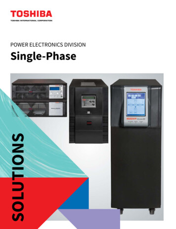
SN74LVC1G00SCES212AB – APRIL 1999 – REVISED APRIL 2014www.ti.comParameter Measurement Information (continued)VLOADS1RLFrom OutputUnder TestOpenTESTGNDCL(see Note A)S1OpenVLOADtPLH/tPHLtPLZ/tPZLtPHZ/tPZHRLGNDLOAD CIRCUITINPUTSVCC1.8 V 0.15 V2.5 V 0.2 V3.3 V 0.3 V5 V 0.5 VVItr/tfVCCVCC3VVCC 2 ns 2 ns 2.5 ns 2.5 nsVMVLOADCLRLVDVCC/2VCC/21.5 VVCC/22 VCC2 VCC6V2 VCC30 pF30 pF50 pF50 pF1 kW500 W500 W500 W0.15 V0.15 V0.3 V0.3 VVITiming InputVM0VtWtsuVIInputVMVMthVIData InputVMVM0V0VVOLTAGE WAVEFORMSPULSE DURATIONVOLTAGE WAVEFORMSSETUP AND HOLD utWaveform 1S1 at VLOAD(see Note utControlVMVOLVOLTAGE WAVEFORMSPROPAGATION DELAY TIMESINVERTING AND NONINVERTING OUTPUTSOutputWaveform 2S1 at GND(see Note B)VOL VDVOLtPHZVMVOH – VDVOH»0 VVOLTAGE WAVEFORMSENABLE AND DISABLE TIMESLOW- AND HIGH-LEVEL ENABLINGNOTES: A. CL includes probe and jig capacitance.B. Waveform 1 is for an output with internal conditions such that the output is low, except when disabled by the output control.Waveform 2 is for an output with internal conditions such that the output is high, except when disabled by the output control.C. All input pulses are supplied by generators having the following characteristics: PRR 10 MHz, ZO 50 W.D. The outputs are measured one at a time, with one transition per measurement.E. tPLZ and tPHZ are the same as tdis.F. tPZL and tPZH are the same as ten.G. tPLH and tPHL are the same as tpd.H. All parameters and waveforms are not applicable to all devices.Figure 4. Load Circuit and Voltage Waveforms8Submit Documentation FeedbackCopyright 1999–2014, Texas Instruments IncorporatedProduct Folder Links: SN74LVC1G00
SN74LVC1G00www.ti.comSCES212AB – APRIL 1999 – REVISED APRIL 20149 Detailed Description9.1 OverviewThe SN74LVC1G00 device contains one 2-input positive-NAND gate and performs the Boolean functionY A B or Y A B. This device is fully specified for partial-power-down applications using Ioff. The Ioffcircuitry disables the outputs, preventing damaging current backflow through the device when it is powereddown.The DPW package technology is a major breakthrough in IC packaging. Its tiny 0.64 mm square footprint savessignificant board space over other package options while still retaining the traditional manufacturing friendly leadpitch of 0.5 mm.9.2 Functional Block Diagram9.3 Feature Description Wide operating voltage range.– Operates from 1.65 V to 5.5 V.Allows down voltage translation.Inputs accept voltages to 5.5 V.Ioff feature allows voltages on the inputs and outputs, when VCC is 0 V.9.4 Device Functional ModesFunction TableINPUTSOUTPUTYABHHLLXHXLHSubmit Documentation FeedbackCopyright 1999–2014, Texas Instruments IncorporatedProduct Folder Links: SN74LVC1G009
SN74LVC1G00SCES212AB – APRIL 1999 – REVISED APRIL 2014www.ti.com10 Application and Implementation10.1 Application InformationThe SN74LVC1G00 is a high drive CMOS device that can be used for implementing NAND logic with a highoutput drive, such as an LED application. It can produce 24 mA of drive current at 3.3 V making it Ideal fordriving multiple outputs and good for high speed applications up to 100 MHz. The inputs are 5.5 V tolerantallowing it to translate down to VCC.10.2 Typical ApplicationBasic LED DriverNAND Logic FunctionuC or LogicuC or LogicuC or LogicLVC1G00LVC1G00uC or LogicuC or Logic10.2.1 Design RequirementsThis device uses CMOS technology and has balanced output drive. Care should be taken to avoid buscontention because it can drive currents that would exceed maximum limits. The high drive will also create fastedges into light loads so routing and load conditions should be considered to prevent ringing.10.2.2 Detailed Design Procedure1. Recommended Input Conditions– Rise time and fall time specs. See (Δt/ΔV) in Recommended Operating Conditions table.– Specified high and low levels. See (VIH and VIL) in Recommended Operating Conditions table.– Inputs are overvoltage tolerant allowing them to go as high as (VI max) in the Recommended OperatingConditions table at any valid VCC.2. Recommend Output Conditions– Load currents should not exceed (IO max) per output and should not exceed total current (continuouscurrent through VCC or GND) for the part. These limits are located in the Absolute Maximum Ratingstable.– Outputs should not be pulled above VCC.10Submit Documentation FeedbackCopyright 1999–2014, Texas Instruments IncorporatedProduct Folder Links: SN74LVC1G00
SN74LVC1G00www.ti.comSCES212AB – APRIL 1999 – REVISED APRIL 2014Typical Application (continued)10.2.3 Application Curves108IccIccIccIcc1.8V2.5V3.3V5VIcc - mA6420-2-2002040Frequency - MHz6080D003Figure 5. Icc vs Frequency11 Power Supply RecommendationsThe power supply can be any voltage between the min and max supply voltage rating located in theRecommended Operating Conditions table.Each Vcc pin should have a good bypass capacitor to prevent power disturbance. For devices with a singlesupply a 0.1-μF capacitor is recommended and if there are multiple Vcc pins then a 0.01-μF or 0.022-μFcapacitor is recommended for each power pin. It is ok to parallel multiple bypass caps to reject differentfrequencies of noise. 0.1-μF and 1-μF capacitors are commonly used in parallel. The bypass capacitor should beinstalled as close to the power pin as possible for best results.12 Layout12.1 Layout GuidelinesWhen using multiple bit logic devices inputs should not ever float. In many cases, functions or parts of functionsof digital logic devices are unused; for example, when only two inputs of a triple-input AND gate are used or only3 of the 4 buffer gates are used. Such input pins should not be left unconnected because the undefined voltagesat the outside connections result in undefined operational states. Specified below are the rules that must beobserved under all circumstances. All unused inputs of digital logic devices must be connected to a high or lowbias to prevent them from floating. The logic level that should be applied to any particular unused input dependson the function of the device. Generally they will be tied to Gnd or Vcc whichever make more sense or is moreconvenient.12.2 Layout ExampleVCCUnused InputInputOutputUnused InputOutputInputSubmit Documentation FeedbackCopyright 1999–2014, Texas Instruments IncorporatedProduct Folder Links: SN74LVC1G0011
SN74LVC1G00SCES212AB – APRIL 1999 – REVISED APRIL 2014www.ti.com13 Device and Documentation Support13.1 TrademarksAll trademarks are the property of their respective owners.13.2 Electrostatic Discharge CautionThese devices have limited built-in ESD protection. The leads should be shorted together or the device placed in conductive foamduring storage or handling to prevent electrostatic damage to the MOS gates.13.3 GlossarySLYZ022 — TI Glossary.This glossary lists and explains terms, acronyms and definitions.14 Mechanical, Packaging, and Orderable InformationThe following pages include mechanical packaging and orderable information. This information is the mostcurrent data available for the designated devices. This data is subject to change without notice and revision ofthis document. For browser-based versions of this data sheet, refer to the left-hand navigation.12Submit Documentation FeedbackCopyright 1999–2014, Texas Instruments IncorporatedProduct Folder Links: SN74LVC1G00
PACKAGE OPTION ADDENDUMwww.ti.com8-Jun-2022PACKAGING INFORMATIONOrderable DeviceStatus(1)Package Type Package Pins PackageDrawingQtyEco Plan(2)Lead finish/Ball materialMSL Peak TempOp Temp ( C)Device 23DBV53000RoHS & GreenNIPDAU SNLevel-1-260C-UNLIM-40 to 125(C005, C00F, C00J,C00K, C00R)(C00H, C00P, C00S)SN74LVC1G00DBVRE4ACTIVESOT-23DBV53000RoHS & GreenNIPDAULevel-1-260C-UNLIM-40 to 0RoHS & GreenNIPDAULevel-1-260C-UNLIM-40 to HS & GreenNIPDAU SNLevel-1-260C-UNLIM-40 to 125(C005, C00F, C00J,C00K, C00R)(C00H, C00P, C00S)SN74LVC1G00DBVTE4ACTIVESOT-23DBV5250RoHS & GreenNIPDAULevel-1-260C-UNLIM-40 to RoHS & GreenNIPDAULevel-1-260C-UNLIM-40 to S & GreenNIPDAU SNLevel-1-260C-UNLIM-40 to 125(CA5, CAF, CAJ, CAK, CAR)(CAH, CAP, CAS)SN74LVC1G00DCKRE4ACTIVESC70DCK53000RoHS & GreenNIPDAULevel-1-260C-UNLIM-40 to 0RoHS & GreenNIPDAULevel-1-260C-UNLIM-40 to HS & GreenNIPDAU SNLevel-1-260C-UNLIM-40 to 125(CA5, CAF, CAJ, CAK, CAR)(CAH, CAP, CAS)SN74LVC1G00DCKTE4ACTIVESC70DCK5250RoHS & GreenNIPDAULevel-1-260C-UNLIM-40 to RoHS & GreenNIPDAULevel-1-260C-UNLIM-40 to RoHS & GreenNIPDAULevel-1-260C-UNLIM-40 to HS & GreenNIPDAUAGLevel-1-260C-UNLIM-40 to 125(CA7, CAR)SamplesSN74LVC1G00DRY2ACTIVESONDRY65000RoHS & Green NIPDAU NIPDAUAGLevel-1-260C-UNLIM-40 to 125CASamplesAddendum-Page 1SamplesSamplesSamplesSamples
PACKAGE OPTION ADDENDUMwww.ti.comOrderable Device8-Jun-2022Status(1)Package Type Package Pins PackageDrawingQtyEco Plan(2)Lead finish/Ball materialMSL Peak TempOp Temp ( C)Device RY65000RoHS & Green NIPDAU NIPDAUAGLevel-1-260C-UNLIM-40 to 125CASamplesSN74LVC1G00DSF2ACTIVESONDSF65000RoHS & Green NIPDAU NIPDAUAGLevel-1-260C-UNLIM-40 to 125CASamplesSN74LVC1G00DSFRACTIVESONDSF65000RoHS & Green NIPDAU NIPDAUAGLevel-1-260C-UNLIM-40 to 125CASamplesSN74LVC1G00YZPRACTIVEDSBGAYZP53000RoHS & GreenLevel-1-260C-UNLIM-40 to 85(CA7, CAN)SamplesSNAGCU(1)The marketing status values are defined as follows:ACTIVE: Product device recommended for new designs.LIFEBUY: TI has announced that the device will be discontinued, and a lifetime-buy period is in effect.NRND: Not recommended for new designs. Device is in production to support existing customers, but TI does not recommend using this part in a new design.PREVIEW: Device has been announced but is not in production. Samples may or may not be available.OBSOLETE: TI has discontinued the production of the device.(2)RoHS: TI defines "RoHS" to mean semiconductor products that are compliant with the current EU RoHS requirements for all 10 RoHS substances, including the requirement that RoHS substancedo not exceed 0.1% by weight in homogeneous materials. Where designed to be soldered at high temperatures, "RoHS" products are suitable for use in specified lead-free processes. TI mayreference these types of products as "Pb-Free".RoHS Exempt: TI defines "RoHS Exempt" to mean products that contain lead but are compliant with EU RoHS pursuant to a specific EU RoHS exemption.Green: TI defines "Green" to mean the content of Chlorine (Cl) and Bromine (Br) based flame retardants meet JS709B low halogen requirements of 1000ppm threshold. Antimony trioxide basedflame retardants must also meet the 1000ppm threshold requirement.(3)MSL, Peak Temp. - The Moisture Sensitivity Level rating according to the JEDEC industry standard classifications, and peak solder temperature.(4)There may be additional marking, which relates to the logo, the lot trace code information, or the environmental category on the device.(5)Multiple Device Markings will be inside parentheses. Only one Device Marking contained in parentheses and separated by a " " will appear on a device. If a line is indented then it is a continuationof the previous line and the two combined represent the entire Device Marking for that device.(6)Lead finish/Ball material - Orderable Devices may have multiple material finish options. Finish options are separated by a vertical ruled line. Lead finish/Ball material values may wrap to twolines if the finish value exceeds the maximum column width.Important Information and Disclaimer:The information provided on this page represents TI's knowledge and belief as of the date that it is provided. TI bases its knowledge and belief on informationprovided by third parties, and makes no representation or warranty as to the accuracy of such information. Efforts are underway to better integrate information from third parties. TI has taken andcontinues to take reasonable steps to provide representative and accurate information but may not have conducted destructive testing or chemical analysis on incoming materials and chemicals.TI and TI suppliers consider certain information to be proprietary, and thus CAS numbers and other limited information may not be available for release.Addendum-Page 2
PACKAGE OPTION ADDENDUMwww.ti.com8-Jun-2022In no event shall TI's liability arising out of such information exceed the total purchase price of the TI part(s) at issue in this document sold by TI to Customer on an annual basis.OTHER QUALIFIED VERSIONS OF SN74LVC1G00 : Enhanced Product : SN74LVC1G00-EPNOTE: Qualified Version Definitions: Enhanced Product - Supports Defense, Aerospace and Medical ApplicationsAddendum-Page 3
PACKAGE MATERIALS INFORMATIONwww.ti.com8-Jun-2022TAPE AND REEL INFORMATIONREEL DIMENSIONSTAPE DIMENSIONSK0P1B0 WReelDiameterCavityA0B0K0WP1A0Dimension designed to accommodate the component widthDimension designed to accommodate the component lengthDimension designed to accommodate the component thicknessOverall width of the carrier tapePitch between successive cavity centersReel Width (W1)QUADRANT ASSIGNMENTS FOR PIN 1 ORIENTATION IN TAPESprocket HolesQ1Q2Q1Q2Q3Q4Q3Q4User Direction of FeedPocket Quadrants*All dimensions are nominalDevicePackage Package PinsType DrawingSPQReelReelA0Diameter Width (mm)(mm) W1 CKTSC70DCK5250178.09.02.42.51.24
Exposure to absolute-maximum-rated conditions for extended periods may affect device reliability. (2) The input and output negative-voltage ratings may be exceeded if the input and output current ratings are observed. (3) The value of VCC is provided in the Recommended Operating Conditions table. 7.2 Handling Ratings MIN MAX UNIT