Transcription
C1 WINDSHIELDRUBBER CHANNEL REPLACEMENTMASACC Tech SessionOcean City, MD3 Oct 2004Version 1Presented By:Ron Dill
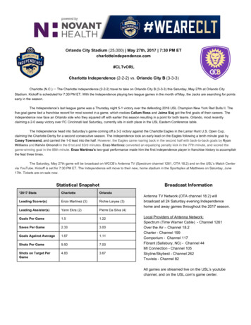
Based largely on an article in the NCRS Corvette Restorer Magazine from the Summer of 1994.After 40 years the rubber channel that surrounds the windshield on my ’61 was pretty muchshot. The rubber was as hard a piece of coal and cracked and broken in many places. Ingeneral, it looked awful and needed to be replaced – for that matter, it needs to be replaced onmany of the C1 cars I recently observed at Carlisle.Back in 1975 I had noticed that the windshield leaked around the gasket when the car wasparked outside in a rain storm. Being a “Shade Tree” mechanic I figured I could fix thisproblem simply and easily by taking the windshield out of the frame and squirting a littlesealer in the gasket channel and then putting the thing back together again. As it turns out,this process was not simple and while I stopped the leak, I broke one layer of the glass in thewindshield – so, not only did I need to replace the rubber channel but the windshield as well.Based on my previous – disastrous – experience, I decided to do a little more research on theprocess before I launched into this particular repair. I searched through the archive of NCRSRestorer Magazines that I have and found an article by John Bellmore which was publishedin the Summer 1994 issue – I’ve reproduced that article here in the handout and it is locatedfor ready reference immediately after my discussion. The article presents a good startingplace and it is a wise restorer that reads it before starting off on this project.In addition, Clymer Publications has a short discussion in their Corvette V8 CompleteOwners Handbook concerning windshield replacement. Their discussion is not very detailed;however, for your information, I’ve reproduced those two pages and included themimmediately after the NCRS article.There is a decent drawing of the windshield assembly in the ’61 Corvette AssemblyInstruction Manual. This is the basic assembly specification for assembly at the plant andI’ve included that drawing after the Owners Handbook pages for your information as well.Finally, I’m sure you all have a copy of the Chevrolet ST-12 Corvette Servicing Guide. Onpage 1-4 it begins a pretty good discussion of how to replace the windshield and how toreassemble the frame. You should certainly read that discussion carefully before starting thisproject – I’ve, once again, included a copy of that discussion at the end of this document.The rubber channel gasket and other parts required for this repair are available throughCorvette Central and Paragon and are probably available in other places but I happen to havethose two parts catalogs and found the necessary parts in both books without difficulty.WINDSHIELD RUBBER CHANNEL REPLACEMENTMr Bellmore’s NCRS article assumes that the car is together when the windshield and frameis to be removed. Since my ’61 is/was “mostly dismantled,” as you can see from the picture,I will abbreviate some of the steps he took and start this presentation with a very basicdiscussion about removing the windshield from the car followed by replacement of the gasketor rubber channel, reassembly and then reinstallation of the frame back on the car body. A2
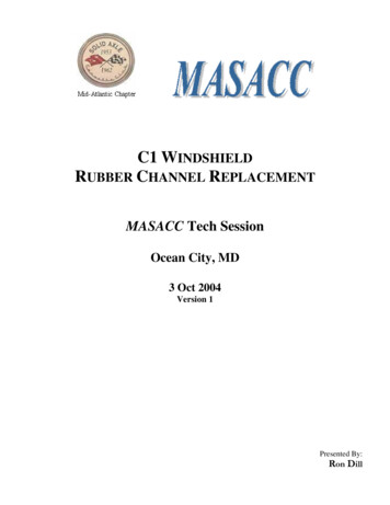
Based largely on an article in the NCRS Corvette Restorer Magazine from the Summer of 1994.new windshield is something over 400, so I would suggest you exercise a certain amount ofcaution when approaching this repair. While the basic instructions in the documents I citedseem to cover the repair pretty well – nothing is ever as easy as it first seems and I’ll try toeducate you on those parts of the process I found particularly difficult or confusing. Thegood thing here is – if you get in totally over your head you can box the whole mess up andsend it off to one of the windshield repair places and they can install new glass (completewith the proper date mark if you desire) and put it all back together again for you – all ittakes is a little .REMOVAL: REMEMBER RULE 1 – You are working with a piece ofGLASS!!I have to tell you – getting the windshieldand frame off the car body is the hard part –taking the frame apart, putting in the newglass or gasket is a difficult process – butgetting to the various bolts under the dash –BOY!!! You will need the package tray,seats and the heater diffuser box out as wellas the dash end caps off. From there you canstart the process of removal. As you can seethere is very little left intact in the cock pit ofthis car.The windshield frame is held to the car bodywith a total of 12 bolts – two bolts at each endare actually studs (5/16X18) in the side frameassembly. The picture at the right shows thosestuds – obviously, in this picture the frame isalready off the car – it makes it easier to seehow the bolts are set up.3
Based largely on an article in the NCRS Corvette Restorer Magazine from the Summer of 1994.The studs have ½” nuts on them that you canget to with a socket if you lift up the edge of thedash pad at the ends. Be advised, I had to use auniversal joint socket to get to the rearmost nuton each side.Somewhere in a previous life, someone had thewindshield off this car because they hadenlarged the access hole so that it is easier to getto the nuts. You can see where the hole was cutwith – probably, a key hole saw. Not veryprofessional, but access to the nuts must reallybe difficult without that hole being enlarged.Once the four ½” nuts are removed from theside frame assemblies, the hard part starts.The front part of the windshield frame is secured to the body with 8 bolts (12X24 with 7/16”nuts), you have to crawl under the dash to remove the nuts on these bolts. Now, you need tounderstand that there are lots of bolts under the dash that look like they could be the onesholding the windshield frame to the dash. The fact of the matter is – they all don’t hold theframe on and the process of determining whichnuts need to be removed and which don’t ispart of what makes this so much fun. There isa clue that can help you in the process. Thefirst small bolt is visible in the picture above inthe first removal paragraph – that bolt is about6 inches forward of the rear most stud on theside post assembly – after that, the bolts are on9 inch centers – so bolts that are not 9 inchesapart probably don’t help hold the frame down.This picture shows the first bolt hole at the leftedge of the light spot and the next hole 9”away at the top right of the picture.4
Based largely on an article in the NCRS Corvette Restorer Magazine from the Summer of 1994.Under the dash is a jumble of wires,defroster hoses, wiper cables, etc. Getting tothe nuts takes a serious amount of patience.The picture at the right shows the passengerside wiper transmission and the defrosteroutlet. You don’t have to take the defrosteroutlet loose but you will have to be amagician to get the frame nut off that istucked under the outside edge of thedefroster outlet. There is a second bolt to theinside of the defroster outlet that does nothave anything to do with the frame assembly. I have taken the defroster outlet loose because– I’m not a magician.This picture shows the drivers side and evenDavid Copperfield would not be able to getthe frame nut off without dropping thedefroster outlet – well, perhaps you could ifthe framework that holds the brake/clutchpedal and steering column were out of the car.It is a very difficult job just to get thedefroster nuts off by themselves, getting themback on will be a genuine treat!!!Once you have the four side post bolts and the 8 front frame nuts off you can grasp the frameby the side posts and lift and rock the frame loose from the car. Now a couple of points –first, you need some help here or you have tohave a build something like a Gorilla becausethe frame is fairly wide and you kind of needto do both sides simultaneously. Second, ifthe frame has never been off the car it shouldcome loose with just a little resistance – if ithas been off before and someone usedsilicone caulk to stick it down and seal it –you are in for a treat!!! If it doesn’t movewith moderate effort, first go back and verifythat you actually removed the correct nutssecuring the frame down – if one is still intactit is going to be tough to get the windshield loose regardless of your build.Once the frame is loose from the body, lay it face down on a padded saw horse or suitablework bench. Handle this thing carefully, the frame provides only moderate support to the5
Based largely on an article in the NCRS Corvette Restorer Magazine from the Summer of 1994.glass and it would be pretty easy to crack the windshield – remember, that’s an additional 400 investment if you have to replace an otherwise serviceable windshield.You will need to remove the 8 screws holdingthe frame together. There are 2 flat headscrews at the bottom of the side post assemblywhere it connects to the bottom frame – justahead of the two studs. The picture at the rightshows the two flat head screws. In addition, itshows a common problem – the front tab onthe side assembly is broken off – you can seethe crack filled with sealer between the middlestud and the middle flathead screw. Thesecond picture displays the broken part a littlebetter. This needs to be fixed before youreassemble the frame. Send the broken sidepost assembly to Corvette Central and forabout 65 they will machine the parts andscrew them together making a “good as new”part. Also, this is a good time to send the twoside post assemblies off to be rechromed – theywill most likely need that done. Rechromingwill run 100 to 220 each depending onwhere you get that accomplished. The top andbottom frame molding is stainless so youmight want to get the buffer out and go over that while you are waiting for the newlychromed side post assemblies.The other 4 screws are at the top of the sidepost assembly – two screws on each side.They are not terribly clear in this picture, butone screw is to the left and one to the right ofthe hard/soft top pilot hole. The obvious screwhole to the left of the pilot hole is the mountinghole for the sun visor. The last screw to theleft is one of 4 that hold the stainless moldingto the upper frame assembly. I removed thosescrews but I don’t believe that they need to beremoved as the stainless and frame assemblyseem to stay together through out this operation.Once the for screws are out, grasp the top of the side post assembly and try to pull it apartfrom the top frame assembly. If it moves, just pull it out ¼” or so. Then grasp the bottom ofthe side post assembly and try to pull it out of the bottom frame assembly. As above, if it6
Based largely on an article in the NCRS Corvette Restorer Magazine from the Summer of 1994.moves, just pull it ¼” or so. Then return to the top and pull it apart some more – you’ll haveto wiggle this around to get the parts apart. And, if someone has put this together in the pastwith silicone sealer or caulk – good luck!!! I’ve heard that people have resorted to rubberhammers to beat the parts apart – but that really won’t be necessary if the original sealer isstill in place.Once the side post are removed you and justpull the bottom and top frame assemblyloose from the window glass. Most likely,the old rubber channel assembly will staystuck to the window. You will need to cleanthe old rubber channel assembly off thewindow glass and throw it away. I suspectthat you will find the rubber about as hard ascoal. It is not a bad idea to mark the bottomedge of the glass at this point. Once out ofthe frame, it is easy to confuse the top of theglass with the bottom.The next move is to clean all the old sealantand putty out of the channels of both theframe and side post assemblies. The sealantsused by the General will clean off prettyeasily – even after 40 years the putty wasstill soft and pliable. If you have a framewhere silicone sealer was used it will take alittle longer. On the side post assemblies formy ’61, there was an ink stamping of a May19, 1961 date and there was an extra smallplastic spacer cemented in the top of the post channel – I didn’t find any such a marking orthe plastic spacer for the 1958 frame I used for parts.When cleaning the upper and lower frameassemblies, pay attention to the floatinganchor plates found at each end of the frameassemblies. These pieces have threadedholes where the screws removed from theside post assemblies attach. In both cases(upper and lower), these pieces will beimmersed in the putty and won’t beimmediately noticeable.7
Based largely on an article in the NCRS Corvette Restorer Magazine from the Summer of 1994.There is a difference between the top andbottom anchor plates – the top plate being thebigger of the two. Keep track of these thingsas you will need them during reassembly.Before reassembly is a good time to chase thethreads on the side frame studs as well as thebottom frame bolts. The threads will be fullof old putty and a small amount of rust.And, while you are cleaning things, don’tforget to clean the windshield channel on thebody of the car. There will be old sealer there that should be removed. Incidentally, unlessyour car has had a complete body off restoration it is likely that the paint in the windshieldchannel is original and should look pretty fresh since it has not been sun faded. This willgive you a pretty good idea of the base color of your car when it was new – of course; thiswon’t help you determine the color of the coves unless the car was a single color car.This ends the removal portion of the process.CHANNEL REPLACEMENT:I assume that you had all the necessary parts to complete this project before you started.However, this is a good point to go over theparts required to put the windshield and frameassembly back together again. First andforemost, you need the new channel assemblygasket (I’ve had the one in the picture, a GMpart, since 1982 – replacements may varyslightly from this one.). And, duringdisassembly I’m certain that the foam rubberfiller used in the top frame was destroyed.There is a rubber strip that goes between thelower frame assembly and the body that mayneed replacement. The final gaskets to have on hand are spacer gaskets that go under the sideposts – these gaskets help adjust the frame to be level on the car. I suspect that not havingthe correct amount of spacers here results in the broken ears on the bottom of the side postassemblies. Finally, it would be a good idea to have some extra nuts and washers on hand forthe reinstallation process – you are gonna drop some of them before this is all back togetheragain!Most of these parts will be used in the reassembly process but you will need the channelgasket and the sealer (mentioned below) during this portion of the process.8
Based largely on an article in the NCRS Corvette Restorer Magazine from the Summer of 1994.In addition to the rubber parts, you will need some sealer to seal thegasket to the glass it self. The stuff used, originally, by the Generalstays pliable through out its life and seems to clean off pretty easily.That material is no longer available but the recommended sealer is a3M product called “Auto Bedding and Glazing Compound 08509, 1/10Gallon (US) Cartridge.” According to 3M, this is a “Non-hardening,pliable, water-resistant, medium-bodied sealer for sealing auto seamsand between windshield rubber and car body. Can be used as asupplementary sealer for auto glass installation.” Some people callthis “Never Dry.” This comes in a tube that you use with a caulkinggun.The rubber channel has to be installed so that it is centered on thewindow glass. That is because of the flap on the bottom inside of therubber channel that covers the front edge of the dash pad where it approaches the windshield.I found it difficult to determine, exactly, thecenter of the windshield because of therounded corners. So, I created a solidmeasurement point by placing the window,bottom side down, on a flat surface (the floor)and then measuring up an equal amount andmarking a spot on each side that I couldmeasure to.After that it was merely a matter of measuringfrom the marked spots to the center of thebottom of the windshield. For installation ofthe rubber channel I don’t believe it isnecessary to mark the center of the top of thewindshield. However, a top center mark willbe helpful when remounting the upper frameassembly.9
Based largely on an article in the NCRS Corvette Restorer Magazine from the Summer of 1994.Next measure the channel gasket and mark the bottom center of the gasket.Put the gasket on the window, without anysealer, to make certain that the gasket fitsproperly. Start at the bottom center and matchthat center mark to the one on the gasket. Fitthe window glass into the channel. I found twothings – 1, you need about 8 hands to put therubber in place and keep it there. While as ayoung man in the back seat of my ’57 Chevy Iwas accused of having 8 hands – it wasn’t truethen and it certainly isn’t true now. So, I gotout a batch of clamps and found that I couldhold the rubber in place on the window while I was fitting the glass to the rest of the channel.As I mentioned I’ve had this rubber channelfor a number of years and new ones may fitdifferently. However, in this case I found thatI had to stretch the rubber substantially to get itto fit. Remember Rule 1. So, I carefullystretched the rubber as I installed it so that thebottom centers remained in agreement and therubber encircled the window.Once certain that the gasket will fit the windowproperly, peal back the gasket and put a smallbead of sealer in the gasket channel – probablyan 1/8” diameter bead will be sufficient. Thishelps hold the gasket in place duringreassembly as well as seals the rubber to theglass itself. I found that the clamps mentionedabove came in handy here as well. I couldplace a clamp in front and back of where I waspealing the rubber back to put in the sealer. Igave myself about 18” or so of working roombetween the clamps and would move theclamps around the working area as I progressed around the window.This ends the part of the process associated with installing the gasket. The next step isreassembly.10
Based largely on an article in the NCRS Corvette Restorer Magazine from the Summer of 1994.REASSEMBLY:NOTE: Some of you sharp eyed restorers may notice that the remaining pictures may look alittle staged. They were – first, as this was written, the Bedding Compound hadn’t come inyet and second, the newly rechromed side posts were still at the chromer. So, since I didn’twant to have to do the complete installation over again when those parts arrived – I stagedthese photos to give you a reasonable example.This portion of the process deals with reattaching the frame to the window and rubberchannel. The frame tends to have a friction fit on the rubber channel so it may be necessaryto use some soap or other non-petroleum based lubricant to allow the rubber to slip into theside post and upper/lower frame assembly slots. And, you are probably gonna want thatrubber hammer!!!Important in the reassembly process is havingthe proper calking material to go in the frameand to hold the anchor plates in place. Theoriginal GM putty is not available; but, 3M hasa suitable substitute. This is 3M Strip-Calk08578 Black, 60-1 ft Strips per box. 3M saysthis is a “Soft non-hardening caulking materialin one foot lengths for use in all types ofseams, joints and openings. This product iseasily thumbed into place and smoothed with afinger. It may be painted immediately.” This is good stuff and you can, also, use it when youmount your chrome trim pieces on the car to seal the hole around the trim mounting spike.Place a strip, or two, of the Strip-Calk in the center of the bottom frame assembly. The StripCalk is supposed to fill the space between thebottom of the slot in the frame assembly andthe rubber channel gasket. Place some StripCalk between the frame and the floatinganchor points and some Strip-Calk on top ofthe anchor point. Try to center the anchorpoints in the lower channel so that thethreaded holes are in the middle of the slots inthe frame. These holes will have to match upwith the bottom holes in the side postassemblies. They probably won’t line up, atleast at first and you will have to “CAREFULLY” use an awl, scribe or something to movethe anchor one way or the other in the slot to match up the holes so that you can insert andtighten the screws.11
Based largely on an article in the NCRS Corvette Restorer Magazine from the Summer of 1994.And, while on the subject of tightening screws – DON’T tighten the screws on the sidepost assemblies until both side posts are in place and you are satisfied with the fit. Atthat point, you can tighten things down.While putting calk on the bottom channel sticksome calk under the heads and around of the “T”bolts used to secure the frame to the body of thecar.Measure and mark the center of the bottom frame assembly. Carefully, slide the bottomframe assembly over the channel gasketkeeping the center mark on the windshield andon the frame assembly aligned. This is easiersaid than done – be careful, take your time andwork it down over the gasket – this is a frictionfit so expect some resistance. As I’d indicatedabove, you may need some lubricant to helpslide the frame over the rubber channel. Whileit is important to keep the center lines close –you will find it easier to start the frameassembly over the rubber channel from theends. I put the glass on the floor, top down, soI could press straight down on the bottom frame assembly to seat it on the rubber channel.Place a bead, or two, of Strip-Calk in the topframe assembly – as above, this should fill thegap between the frame assembly and thebottom of the rubber gasket. In addition, inthe upper frame assembly there is a piece ofsponge rubber that goes in the top channel –apparently, they found that the windows andframe had more space than was desired in thetop portion of the frame assembly andinstalled this sponge spacer. Place the topframe assembly over the rubber gasket beingcareful to have the frame fairly closely centered on the top of the window.12
Based largely on an article in the NCRS Corvette Restorer Magazine from the Summer of 1994.Also, as mentioned above, place Strip-Calk under and over the floating anchor points. As theside posts are put in place the top and bottom frame assemblies may have to be movedslightly from one side to the other to get a perfect fit.Put a bead, or two, of Strip-Calk in the channelof each side post assembly. Carefully work theside post assemblies into place in the frame.They should, with minor resistance, slide intothe ends of the top and bottom frame assembly.I expect you may need the rubber hammerhere. The upper frame assembly expands withthe rubber channel and that part of the framehas a very close fit into the top of the side postassembly. The last half inch you see in thepicture is a bit of a problem!!The bottom goes into place very easily. Thetop is the problem. You will want to put someStrip-Calk at the joint where the top andbottom of the side post assemblies fit together.Once both sides are in place and you aresatisfied with their placement. It is time to putthe four (2 flat head on the bottom and 2chromed screws in the top) screws in the sidepost assemblies. This is often a very ticklishprocess – most certainly you will have to use ascribe or something to move the anchor platesinto position so that they will accept the screws. Be very careful, while there is a rubberchannel gasket between the floating anchor and the glass of the window it is possible to getheavy handed and push a sharp scribe through the rubber and scratch the edge of the glass –if this happens – most certainly the glass will crack! (Been there, done that!!!)Once the anchor plates are aligned, replace the screws – don’t tighten until all 8 screws are inplace. Once you satisfied, tighten the screws.At this point, I would carefully clean the windshield and remove excess putty and sealer.The window will get dirty again before you get it fully installed back on the car but it iseasier to clean there on the bench so I’d get the worst of the mess cleaned up/off at this point.This finishes the reassembly of the frame. The remainder of the process is associated withthe reinstallation of the frame and window onto the car body.13
Based largely on an article in the NCRS Corvette Restorer Magazine from the Summer of 1994.However, before we move on toreinstallation, a word about the differences inthe side post assemblies is in order. Ireplaced the broken side post assembly onmy ’61 with one from a ’58 frame. As nearas I could tell they were identical except forthe fact that my ’61 was equipped with sunvisors and the ’58 was not. As a result, therewas a threaded hole missing in the top of theside post assembly where the end of thevisor would be secured. You can see thedifference in this picture – the left assembly has the visor hole. I drilled and tapped anappropriate hole before I sent the side posts off to be rechromed.REINSTALLATION:Carefully turn the window assembly over so that the bottom frame assembly and the 4 studson the side post assemblies are exposed.There is a rubber strip that goes between the lower frame assembly and the body of the car(the curved side of the rubber strip goestowards the frame and the flat side towardsthe car body) as well as some rubberspacers that fit over the base of the side postassemblies. The purpose of the rubberspacers is to try to even out any differencesin height between the base of the side postassembly and the bottom of the rubber stripwhere it contacts the car body. Take sometime while the window assembly is on thebench to look at the height differential.When you tighten the windshield bolts down in the car, if there is much difference in heightbetween the side post and bottom frame rubber things will be tightened in a bind – usually,this bind can result in breaking the front ear off of the side post assembly. The frame andside post bolts can be tightened pretty snug but you don’t have to over tighten them, after allthere is rubber between both the frame and the side posts and the car body. You over tightenand the rubber will be over stressed or “squashed” and you are liable to break the side postears off.Put a bead of the Strip-Calk between the bottom frame and the rubber spacer. Place therubber spacer over the bolts on the bottom frame assembly. Press the spacer down on theframe assembly – the Stick-Calk will stick to both parts and hold the rubber spacer in place.14
Based largely on an article in the NCRS Corvette Restorer Magazine from the Summer of 1994.Place some Stick-Calk on the side posts between the base and the spacers. Press the spacergaskets into place on the side posts.On the body of the car, run a bead of Strip-Calk in the windshield channel between the boltholes. When the windshield frame assembly is put on the car – the rubber spacer gasketshould flatten this strip of calk out sealing the windshield to the car body. I believe that youcould use something besides the Strip-Calk here but it seals nicely and allows you to be ableto take the windshield off the body at some future date – anything else will probably set uplike glue.Using a helper, lift the window and frame assembly up and lower it onto the car body –making certain that the lower frame and side post bolts go through the appropriate holes.Reinstall all the nuts and washers removedearlier when the windshield assembly wasremoved from the car. Tighten the boltscarefully – I try to tighten them equally withthe final tightening from the side poststowards the center of the windshield.Reinstall the package tray, the seats andanything else you removed to get to theunderside of the dash.Wash the window and polish thechrome/stainless and you are finished. A VERY tough job well done. Hopefully, you won’thave to do this again for another 40 years.I would not expect the windshield frame or the rubber channel to leak even in the mostdifficult of storms – but if it does, it is very unlikely you’ll be able to differentiate that leakfrom the rest of the leaks common to C-1 Corvettes.15
Based largely on an article in the NCRS Corvette Restorer Magazine from the Summer of 1994.16
Based largely on an article in the NCRS Corvette Restorer Magazine from the Summer of 1994.17
Based largely on an article in the NCRS Corvette Restorer Magazine from the Summer of 1994.18
Extracted from Clymer Publications – Corvette V8 1955 – 1962 Complete Owners Handbook.19
Extracted from the ’61 Corvette Assembly Instruction Manual.20
Extracted from the ’61 Corvette Assembly Instruction Manual.21
Extracted from the Chevrolet Corvette Servicing Guide dated 1962.22
Extracted from the Chevrolet Corvette Servicing Guide dated 1962.23
Extracted from the Chevrolet Corvette Servicing Guide dated 1962.24
those two parts catalogs and found the necessary parts in both books without difficulty. WINDSHIELD RUBBER CHANNEL REPLACEMENT Mr Bellmore's NCRS article assumes that the car is together when the windshield and frame is to be removed. Since my '61 is/was "mostly dismantled," as you can see from the picture,