Transcription
26 Understand the working of basic networkingcommands (Ping, Route Add/Delete/Print,ACL)26.1 TheoryNetSim allows users to interact with the simulation at runtime via a socket or through a file. UserInteractions make simulation more realistic by allowing command execution to view/modifycertain device parameters during runtime.26.1.1 Ping Command The ping command is one of the most often used networking utilities for troubleshootingnetwork problems. You can use the ping command to test the availability of a networking device (usually acomputer) on a network When you ping a device, you send that device a short message, which it then sends back(the echo) If you receive a reply then the device is in the Network, if you do not, then the device isfaulty, disconnected, switched off, or incorrectly configured.26.1.2 Route CommandsYou can use the route commands to view, add and delete routes in IP routing tables. route print: In order to view the entire contents of the IP routing table. route delete: In order to delete all routes in the IP routing table. route add: In order to add a static TCP/IP route to the IP routing table.26.1.3 ACL ConfigurationRouters provide basic traffic filtering capabilities, such as blocking the Internet traffic withaccess control lists (ACLs). An ACL is a sequential list of Permit or Deny statements that applyto addresses or upper-layer protocols. These lists tell the router what types of packets to:PERMIT or DENY. When using an access-list to filter traffic, a PERMIT statement is used to“allow” traffic, while a DENY statement is used to “block” traffic.Ver 13.11
26.2 Network setupOpen NetSim and click Examples Experiments nt-and-ACL Sample-1 as shown below Figure 26-1.Figure 26-1: Experiments ListNetSim UI displays the configuration file corresponding to this experiment as shown belowFigure 26-2.Figure 26-2: Network topology in the sample scenario26.3 ProcedureThe following set of procedures were done to generate this sample:Ver 13.12
Step 1: A network scenario is designed in NetSim GUI comprising of 2 Wired Nodes and 3Routers in the “Internetworks” Network Library.Step 2: In the Network Layer properties of Wired Node 1, “ICMP Status” is set as TRUE.Similarly, ICMP Status is set as TRUE for all the devices as shown Figure 26-3.Figure 26-3: Network Layer properties of Wired Node 1Step 3: In the General properties of Wired Node 1, Wireshark Capture is set as Online.Step 4: Right click on the Application Flow App1 CBR and select Properties or click on theApplication icon present in the top ribbon/toolbar.A CBR Application is generated from Wired Node 1 i.e. Source to Wired Node 2 i.e. Destinationwith Packet Size remaining 1460Bytes and Inter Arrival Time remaining 233.6µs. TransportProtocol is set to UDP.Additionally, the “Start Time(s)” parameter is set to 30, while configuring the application. Thistime is usually set to be greater than the time taken for OSPF Convergence (i.e., Exchange ofOSPF information between all the routers), and it increases as the size of the networkincreases.Step 5: Packet Trace is enabled in NetSim GUI. At the end of the simulation, a very large .csvfile is containing all the packet information is available for the users to perform packet levelanalysis. Plots are enabled in NetSim GUI.Step 6: Click on Run Simulation. Simulation Time is set to 300 Seconds and in the RuntimeInteraction tab Figure 26-4, Interactive Simulation is set to True.Ver 13.13
Figure 26-4: Runtime Interaction windowNOTE: It is recommended to specify a longer simulation time to ensure that there is sufficient time for theuser to execute the various commands and see the effect of that before the Simulation ends.Click on Accept and then click on OK. Simulation (NetSimCore.exe) will start running and will display a message “waiting forfirst client to connect” as shown below Figure 26-5Figure 26-5: Waiting for first client to connect Go back to the network scenario. Click on “Display Settings” in the top ribbon/toolbarand select the “Device IP” checkbox inorder to display the IP address of all the devices.Now, Right click on Router 3 or any other Router and select “NetSim Console” option asshown Figure 26-6.Ver 13.14
Figure 26-6: Select NetSim Console Now Client (NetSimCLI.exe) will start running and it will try to establish aconnection with NetSimCore.exe. After the connection is established, the followingwill be displayed Figure 26-7.Figure 26-7: Connection established After this the command line interface can be used to execute all the supported commands.26.4 Network Commands26.4.1 Ping Command You can use the ping command with an IP address or Device name. ICMP Status should be set as True in all nodes for ping to work.Ping IP address e.g. ping 11.4.1.2Ping Node Name e.g. ping Wired Node 2Ver 13.15
Figure 26-8: Pinging Wired Node 226.4.2 Route Commands In order to view the entire contents of the IP routing table, use following command routeprintroute printFigure 26-9: IP routing table You’ll see the routing table entries with network destinations and the gateways to whichpackets are forwarded, when they are headed to that destination. Unless you’ve alreadyadded static routes to the table, everything you see here is dynamically generated. In order to delete a route in the IP routing table you’ll type a command using the followingsyntaxroute delete destination networkVer 13.16
So, to delete the route with destination network 11.5.1.2, all we’d have to do is type thiscommand.route delete 11.5.1.2 To check whether route has been deleted or not check again using route print command. To add a static route to the table, you will type a command using the following syntax.route ADD destination network MASK subnet mask gateway ip metric cost interface So, for example, if you wanted to add a route specifying that all traffic bound for the11.5.1.2 subnet went to a gateway at 11.5.1.1route ADD 11.5.1.2 MASK 255.255.0.0 11.5.1.1 METRIC 100 IF 2 If you were to use the route print command to look at the table now, you’d see your newstatic route.Figure 26-10: Route delete/ Route addVer 13.17
NOTE: Entry added in IP table by routing protocol continuously gets updated. If a user tries to remove aroute via route delete command, there is always a chance that routing protocol will re-enter this entry again.Users can use ACL / Static route to override the routing protocol entry if required.26.4.3 ACL ConfigurationCommands to configure ACL To view ACL syntax: acl print Before using ACL, we must first verify whether ACL option enabled. A common way toenable ACL is to use command: ACL Enable Enter configuration mode of ACL: aclconfig To view ACL Table: Print To exit from ACL configuration: exit To disable ACL: ACL Disable (use this command after exit from ACL Configuration)To view ACL usage syntax use: acl print[PERMIT, DENY] [INBOUND, OUTBOUND, BOTH] PROTO SRC DEST SPORT DPORT IFID26.4.4 Step to Configure ACL To create a new rule in the ACL use command as shown below to block UDP packet inInterface 2 and Interface 3 of Router 3. Application properties Transport Protocol UDP as shown Figure 26-11.Ver 13.18
Figure 26-11: Application properties window Use the command as follows Figure 26-12.NetSim acl enableACL is enableNetSim aclconfigROUTER 3/ACLCONFIG acl printUsage: [PERMIT, DENY] [INBOUND, OUTBOUND, BOTH] PROTO SRC DEST SPORTDPORT IFIDVer 13.19
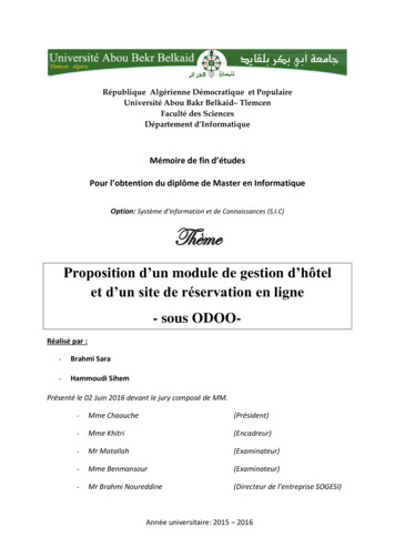
ROUTER 3/ACLCONFIG DENY BOTH UDP ANY ANY 0 0 2OK!ROUTER 3/ACLCONFIG DENY BOTH UDP ANY ANY 0 0 3OK!ROUTER 3/ACLCONFIG printDENY BOTH UDP ANY/0 ANY/0 0 0 2DENY BOTH UDP ANY/0 ANY/0 0 0 3ROUTER 3/ACLCONFIG exitNetSim acl disableACL is disableNetSim Figure 26-12: ACL Configuration command26.4.5 Ping Command ResultsGo to the Results Dashboard and click on “Open Packet Trace” option present in the LeftHand-Side of the window and do the following:Filter Control Packet Type/App Name to ICMP EchoRequest and ICMP EchoReply as shownFigure 26-13.Ver 13.110
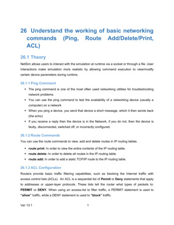
Figure 26-13: Packet Trace - ICMP Control PacketsIn Wireshark, apply filter as ICMP. we can see the ping request and reply packets in Wiresharkas shown Figure 26-14.Figure 26-14: ICMP Control packets in Wireshark26.4.6 ACL ResultsThe impact of ACL rule applied over the simulation traffic can be observed in the IP MetricsTable in the simulation results window. In Router 3, the number of packets blocked by firewallhas been shown below Figure 26-15.Ver 13.111
Figure 26-15: IP Metrics Table in result windowNOTE: Number of packets blocked may vary based on the time at which ACL is configured.Users can also observe this in Packet Animation before and after the Packets are blocked asshown below Figure 26-16/Figure 26-17.Figure 26-16: In Animation Window before applying ACL rules see the packet flowVer 13.112
Figure 26-17: In Animation Window after applying ACL rules see the packet flow Check Packet animation window whether packets has been blocked in Router 3 or notafter entering ACL command to deny UDP traffic. Before applying ACL rule there is packet flow from Wired Node 1 to Wired Node 2 After applying ACL rule Packet flows up to Router 3 only.Ver 13.113
In Wireshark, apply filter as ICMP. we can see the ping request and reply packets in Wireshark as shown . Figure 26-14. Figure 26-14: ICMP Control packets in Wireshark. 26.4.6 ACL Results . The impact of ACL rule applied over the simulation traffic can be observed in the IP Metrics Table in the simulation results window.