Transcription
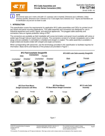
Application SpecificationM12 Cable Assemblies andCircular Series Connectors (CSC)114-13714429 AUG 19 REV. A3NOTEAll numerical values are in metric units [with U.S. customary units in brackets]. Dimensions are in millimeters. Unlessotherwise specified, dimensions have a tolerance of 0.13 and angles have a tolerance of 2 . Figures and illustrations arefor identification only and are not drawn to scale.1. INTRODUCTIONThis specification covers the requirements for application M12 cable assemblies and CSCs for printed circuit(pc) board and panel mounting applications. The cable assembly and connectors are designed for use inindustrial equipment and control, signal, and electrical appliances. The plugged cable assembly andconnectors have an ingress protection rating of IP67.The connectors are available as field installable with screw termination and panel mount available with wires orsolder type through-hole pc board mount contacts. The connectors consist of a female (receptacle) and a male(plug) and are available in unshielded or shielded and straight or angled. The cable assembly is available insingle ended and double ended with straight and angle connectors.When corresponding with personnel, use the terminology provided in this specification to facilitate inquiries forinformation. Basic terms and features of this product are provided in Figure 1.M12 Front Panel MountStraight Connectors with WiresMaleFemaleM12 Panel MountPC Board Mount Straight ConnectorsMaleM12 X code CableAssemblyFemaleFigure 1 2019 TE Connectivity family of companiesAll Rights Reserved*TrademarkTOOLING ASSISTANCE CENTER 1-800-722-1111PRODUCT INFORMATION 1-800-522-6752This controlled document is subject to change.For latest revision and Regional Customer Service,visit our website at www.te.com.TE Connectivity, TE connectivity (logo), and TE (logo) are trademarks. Other logos, product, and/or company names may be trademarks of their respective owners.1 of 7
114-1371442. REFERENCE MATERIAL2.1. Revision SummaryInitial release of application specification2.2. Customer AssistanceReference Product Base Part NumbersT411XXXXXXX-XXX (M12 field installable connector) andT413XXXXXXX-XXX (M12 panel mount sold type connector) andT414XXXXXXX-XXX (M12 panel mount PCB solder type connector) andT417XXXXXXX-XXX (M12 panel mount connector with wire) andT415XXXXXXX-XXX (M12 cable assembly, un-shielded type) andT416XXXXXXX-XXX (M12 cable assembly, shielded type)TAAXXXXXXXX-XXX,TABXXXXXXXX-XXX (M12 cable assembly for field bus applications)TADXXXXXXXX-XXX (M12 cable assembly industrial ethernet applications)Use of these numbers will identify the product line and help you to obtain product and tooling information. Suchinformation can be obtained through a local Representative, by visiting our website at www.te.com, or by callingPRODUCT INFORMATION or the TOOLING ASSISTANCE CENTER at the numbers at the bottom of page 1.2.3. DrawingsCustomer Drawings for product part numbers are available from the service network. If there is a conflictbetween the information contained in the Customer Drawings and this specification or with any other technicaldocumentation supplied, the information contained in the Customer Drawings takes priority.2.4. SpecificationsProduct Specification 108-106140 provides product performance and test requirements.2.5. Instructional MaterialInstruction Sheets (408-series) provide product assembly instructions.2.6. Standards and PublicationsStandards and publications developed by the International Electrotechnical Commission (IEC) provide industrytest and performance requirements. Standards available that pertain to this product are:IEC 61076-2-101, “Connectors for Electronic Equipment—Product Requirements—Part 2-101: CircularConnectors—Detail Specification for M12 Connectors with Screw Locking”IEC 61076-2-104, “Connectors for Electronic Equipment—Product Requirements—Part 2-104: CircularConnectors—Detail Specification for Circular Connectors with M8 Screw Locking or Snap Locking”IEC 61076-2-109, “Connectors for Electronic Equipment—Product Requirements—Part 2-109: CircularConnectors—Detail Specification for Connectors with M12*1 Screw Locking for Data TransmissionFrequencies Up to 500 MHz”IEC 61076-2-1112.7. ManualsManual 402-40 can be used as a guide to soldering. This manual provides information on various flux typesand characteristics with the commercial designation, flux removal procedures, and a guide for information onsoldering problems.A32 of 7
114-1371443. REQUIREMENTS3.1. StorageA. Ultraviolet LightProlonged exposure to ultraviolet light may deteriorate the chemical composition used in the productmaterial.B. Shelf LifeThe product should remain in the shipping containers until ready for use to prevent deformation tocomponents. The product should be used on a first in, first out basis to avoid storage contamination thatcould adversely affect performance.C. Chemical ExposureDo not store product near any chemical listed below as they may cause stress corrosion cracking in sNitritesPhosphates CitratesSulfur NitritesSulfur CompoundsTartrates3.2. Operating TemperatureThe cable assemblies and connectors must be used within the operating temperature given on the customerdrawing for the specific connector.3.3. Cable SelectionThe connectors accept cable having the requirements given on the specific connector customer drawing.In this specification, when the connector assembly procedure depends on the cable shield outer diameter, thatdiameter is included in the assembly requirements of Paragraph 3.4.3.4. M12 Cable Preparation and Connector AssemblyA. M12 Field Installable Connectors (T411)These connectors must meet the cable preparation and connector assembly requirements given inError! Reference source not found. and Figure 3.B. Cable Assembly (T415/6,TAA,TAB,TAD)Cable assembly have code indicator for easily assembly as shown in customer drawing.The cable of the cable assembly must remain perpendicular to the connector and avoid an excessivelysharp bend radius and loading. The minimum bend radius of a cable is 10 .Must not unlock and un-screw the male(plug) nut rudly, which will be get stuck due to specialstructure design.Tips: At the same time of un-screw, a bit pull out force will help unlock easily.Un-screwPull-outA33 of 7
114-137144M12 Field Installable ConnectorUnshielded Cable3-12-Position ConnectorsStraight ConnectorDIMENSION ATERMINATION1.Connector components install on cable2.Cable jacket should be stripped as shown3.For 3-8-position, install wire to correct insert position(wire plug should be preferred to crimp on the wire)4.Turn the M2.5 screw with suitable tool, torque to0.2Nm [1.77 in.-lb.]For 12-position, sold the wireSCREWSOLDER53.55.Install straight housing6.Install seal, pinch ring, pressing screw7.Pressing screw should be tightened with torquerecommended as 1 Nm [8.85 in.-lb.]8.Cable outlet: PG7 (cable feed: 4-6mm)Unshielded Cable3-12-Position ConnectorsRight Angle ConnectorPG9 (cable feed: 6-8mm)1.2.3.4.Connector components install on cableCable jacket should be stripped as shown.For 3-8-position, install wire to correct insert position(wire plug should be preferred to crimp on the wire)Turn the M2.5 screw with suitable tool, torque to0.2Nm [1.77 in.-lb.]For 12-position, sold the wire5.Install straight housing6.Install seal, pinch ring, pressing screw7.Pressing screw should be tightened with torquerecommended as 1 Nm [8.85 in.-lb.]8.Cable outlet: PG7 (cable feed: 4-6mm)PG9 (cable feed: 6-8mm)A34 of 7
114-137144Figure 2 (End)M12 Field Installable Connector Shield type1. Connector components must beinstalled on cable.2. Cable jacket must be stripped.3. Housing, shielding ring, sealing ring,and pinch ring must be installed overindividual wires and onto cable.4. Pressing screw must be tightened:torque of 1 Nm [8.85 in.-lb]5. For right-angle connector, lockingscrew must be tightened.6. Cable outlet:PG7 (cable feed: 4-6mm)PG9 (cable feed: 6-8mm)StraightRight angleA35 of 7
114-137144Figure 3 (End)3.5. PanelA. Recommended Thickness and Cutout refer to customer drawingThe panel thickness shall be 2.5mm-4.0mm for female rear panel mount, other types 2.5mm. Therecommended panel cutouts are given in Figure 4.Recommended Panel Cutout for M12 ConnectorsWith Bore HoleWith Screw HoleDIMENSIONABCABCPG 915.416.2PG 9M16*1.516.117M16*1.5M20*1.520.121M20*1.51 45 13.6Figure 4B. There are two rotational orientations for mounting the connector to the panel: top/bottom and left/right.This orientation must be chosen before creating the cutout in the panel. Figure 4C. MountingThe connector is designed to be front or rear panel mounted. The mounted connector must meet thefollowing requirements:— the flat of the connector must be aligned with the flat edge cut in the panel— the O-ring must be between the flange and the panel, beside the panel chamfer side— the gasket must be flat against the panel— the panel nut must be flat against the panel and tight to the torque given in Figure 5SCREW TYPETORQUE (Nm [lb-ft])Metal HousingM12*1, PG9,M16*1.5,M20*1.51.0 [0.74]Figure 53.6. Mating and Un-matingDANGERTo avoid personal injury, these connectors and cable assemblies must not be mated or unmated under live conditions(electrical load).A36 of 7
114-137144The recommended torque for mating the connectors is:M12 connectors: 0.6 Nm [0.44 lb-ft]3.7. Replacement and RepairThese cable assemblies and connectors are not repairable. Damaged or defective components must not beused. Connectors must not be re-used by removing the cable.Fitting and servicing should only be performed by qualified personnel in accordance with all guidelines andstandards.4. QUALIFICATIONM12 cable assemblies are recognized by Underwriters Laboratories Inc. (UL)5. TOOLINGNo tooling is required for assembly of M12 cable assemblies and CSC.A37 of 7
This specification covers the requirements for application M12 cable assemblies and CSCs for printed circuit (pc) board and panel mounting applications. The cable assembly and connectors are designed for use in . IEC 61076-2-104, "Connectors for Electronic Equipment—Product Requirements—Part 2-104: Circular .