Transcription
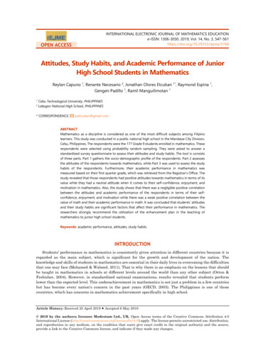
1A Junior Design ReportforFirefighting Robot Development at NMT EE DepartmentPrepared forDr. Aly El-Osery and Dr. Kevin WedewardNew Mexico Institute of Mining and TechnologySocorro, New MexicoFigure 1: Final Design (The Golden Chihuahua)By William Feilner, Jordan Keeley, Marco Martinez, and Jeremy SmithEE Department Robot DevelopmentTeam Excellent ExtinguishersMay 7, 2014
2TABLE OF CONTENTSPAGELIST OF FIGURES .iiABSTRACT . . .iiiINTRODUCTION .iiiRoboRave Rules and Specifications .ivRules Changes .vClass Requirements .viOVERVIEW OF DESIGN. .1CHASSIS AND MOUNTING .2SUBSYSTEMS .4Microcontroller . . .4Motors and Encoders . . 6Extinguishing System . 8Flame Sensors . . . .10Line Sensors . . .16Distance Sensors. . . 19CODE FUNCTIONALITY . . .20BUDGET .23CONCLUSION . .24REFERENCES .24
3LIST OF FIGURESFIGUREDESCRIPTIONPAGEFigure 1Final Design (The Golden Chihuahua)TitleFigure 2System Block Diagram1Figure 3Component Configuration2Figure 4SainSmart L298N Dual H Bridge DC Motor Driver3Figure 5SainSmart 4WD Drive Aluminum Mobile Car Robot Platform3Figure 6SainSmart Arduino Mega5Figure 7Pololu Micro Metal Gearmotor6Figure 8Pololu Motor Encoder6Figure 9PWM Signals Generated By Encoder Channels7Figure 10Wrobot Fan Module9Figure 11Relative Energy vs. Wavelength (Spectrometer)10Figure 12IR Flame Sensor Circuit Diagram11Figure 13Custom Built Flame Sensor14Figure 14Flame Sensor Output at 2 Feet (5V Input)14Figure 15Flame Sensor Output vs. Distance15Figure 16Line Sensor Circuit Diagram16Figure 17Custom Built Line Sensor17Figure 18Line Sensor Output vs. Distance18Figure 19SainSmart Ultrasonic Module HC-SR04 Distance Sensor19Figure 20Ultrasonic Distance Ratings20Figure 21Original Search Algorithm Concept22Figure 22Final Budget23
4ABSTRACTA fully autonomous firefighting robot was constructed that included two custom sensors.The robot was demonstrated to be capable of calculating its distance from an inanimate objectusing ultrasonic distance sensors, distance from a lit candle using IR flame sensors, the relativecolor of the ground it passed over using IR line sensors, and the distance it travelled using motorencoders. In addition, the robot used a motor driver circuit, motors, and four wheels to maneuveritself around a designated field and position itself within extinguishing range of the fire danger.The extinguishing system was shown to be appropriately powerful to only extinguish the flamewhen within the correct range. Finally, all subsystems were integrated into a fully functionalautonomous robot that was able to extinguish four flames in under three minutes.INTRODUCTIONThe EE 382 project chosen by the group was the RoboRave firefighting challenge. Thecore task assigned was to create and program a fully autonomous robot that could avoidobstacles, detect and extinguish candles within a 3 minute time frame. Custom componentsapplying concepts from either analog electronic or electricity and magnetism courses were alsorequired. The problem solving approach taken by the team to complete the task divided the robotup into 5 subsystems: Flame sensing, distance sensing and line sensing, extinguishing andmovement. An Arduino based microcontroller (SainSmart Mega) was used to control allsubsystems. As the extinguishing system was a single fan, it was easily integrated. The customline component the group decided on was a photosensitive circuit whose voltage output could beinterpreted by the on board analog to digital converters in the microcontroller. 3 ultrasonic
5distance sensors were utilized to detect distance relative to the robot. An H bridge motorcontroller was controlled with the controller via PWM (pulse width modulated) signals tomonitor and manipulate motor rotations. To identify obstacles and find candles, a searchingalgorithm was programmed so that the robot navigated evenly throughout the playing area.Once the project was complete, the robot ran on a candle course in lab and later at the officialRoboRave competition in Albuquerque, NM.The Fire Fighting challenge rules, as defined by RoboRave:Autonomous robot programed on any platform.Programming that will move the robot within 8 inches (20.3 cm) or less of a candle beforeextinguishing the flame.Extinguishing system that does not require direct contact with the candle.Complete system cost that does not exceed 1500 total value (regardless of how the parts wereacquired).Teams must be able to produce an itemized materials list if cost is called into questionduring the competitionPlaying field specifications:A white, 1.0 inch (2.54 cm) wide circle with an 8″ (20.3 cm) radius, as measured from thecandle’s base, will be marked on the track around each candle Robot starts at a predesignatedarea on corner of track. The candle’s base diameter is 2.75 inches (7 cm).Some part of the robot must be on or inside the circle while the candle is extinguished; if therobot is NOT on or inside the circle, and the candle is extinguished, a 50% penalty of thecandle’s value will be deducted.
6The robot will have 3 minutes to extinguish the candles.Robot’s base area must be 144 square inches (929 square cm) or less; the robot’s height,however, can be unlimited.The mechanism for extinguishing any candle must be programmed to turn ON only after it stopsat a candle and then turns OFF while it seeks the next candle; the robot may operate inside,along, or outside the perimeter border; the border is provided for those teams who design to use aline following sensor.Touching your robot during 3-minute heat ends the heat; however, multiple heats can be run bythe same team on one of 4 tracks, chosen by the team.Any team that successfully extinguishes ALL four candles during a 3-minute TOURNAMENTheat (not during morning trials) wins the Wilkinson Award ( 200).Rules Changes During Competition:The rules given to teams on site stated that the fan mechanism may be on at all times, regardlessof the distance to the candle. Also, the circles around the candle, now a white paper with a blackline printed on it, were optional and teams could run trials with or without the circles. Candleswere also allowed to be tipped over after they were extinguished.
7Class Requirements:In addition to following the RoboRave rules, some parameters were set as part of EE 382:The robot may not be a previously fabricated system, (such as Lego Mindstorms). Also, the useof custom individual components was strongly encouraged to prevent the project from beingentirely code-based. A 325 dollar budget was given to the group, as well as access to the spareparts from previous EE 382 projects. One of the main requirements outlined in the junior designproject was the design and implementation of a key component using concepts from Analog orElectricity and Magnetism courses.OVERVIEW OF DESIGNOur robot was designed to be simple and effective while maintaining a robust appearanceand performance. The following figure depicts the different systems and how they interact withone another:MicrocontrollerFigure 2: System Block Diagram
8With this overview in mind, we researched several different possibilities for every component.Alternative solutions for microcontrollers included Raspberry Pi, BeagleBone, Intel Galileo, andArduino Mega; for motor control included gyroscopes and encoders; for flame extinguishingincluded compressed air, air cannon, balloons, and fans; for flame detection included ultraviolet(UV) and IR; and, finally, for proximity detection included infrared (IR), light, and ultrasonic.We eventually decided on the following components (as discussed later in the report): ArduinoMega microcontroller, motor encoders, a fan, flame detecting IR sensors, and distance detectingultrasonic sensors. Additionally, we obtained a SainSmart 4WD Chassis, micro metal gearmotors(30:1), 42x19mm wheels, and IR LED’s/IR Phototransistors (for line sensor design). Figure 3, asfollows, details the composition and orientation of the aforementioned parts:Figure 3: Component Configuration
9CHASSIS AND MOUNTINGAs seen in Figure 3, the sensors (three of each: flame, distance, and line) and the fan arelocated on the front end of the robot, and the microcontroller is located on the back. The 9Vbattery supplying power to the microcontrolleris also mounted on the back. Inside the robotare the motors, motor encoders (on the fronttwo motors), a motor controller/driver, and sixAA batteries in series (totaling 9V) to powerthe motor controller. The motor controller, aspictured in Figure 4 below, was controlled via5V digital output from the microcontroller. Ofthe four outputs, two were designated as apositive (forward) charge to the motors and two were negatively (reverse) charged.Figure 4: SainSmart L298NDual H Bridge DC Motor DriverFigure 5: SainSmart 4WD DriveAluminum Mobile Car Robot Platform
10Figure 5 above is the chassis kit that was ordered from SainSmart to accommodate ourneeds. Due to the inadequate torque of the motors, however, we needed to order new motors andwheels. In doing so, cuts were made into the chassis and an adjustment was made to mount thetwo rear motors. This adjustment consisted of two metal sheets to hold the motors in place, muchlike the encoders for the front motors. After initial assembly, we noticed that there were notenough 5V and ground pins on the microcontroller for all the sensors, so a power/ground buswas later added to provide easy access. Finally, a metal arm was mounted on the front of therobot so that the IR sensors and fan would be high enough to detect and extinguish the 10 inchtall candles. Altogether, the additions to our robot were in the interest of efficiency/functionalityat no cost to simplicity or its appearance.SUBSYSTEMSMicrocontrollerThe robot will be controlled by a microcontroller. An Arduino compatiblemicrocontroller was chosen for this project (Figure 6). Arduino refers to a set of specificationsthat a microcontroller follows, making tasks like programming and connecting peripherals muchless cumbersome. Another advantage of using Arduino microcontrollers is their low price point.The average price is about 25 to 35 while the average price for other, more complex,microcontrollers, such as Linux based computer, is 50 to 100.One of the constraints of using an Arduino microcontroller for an autonomous robot isthe number of available ports on the circuit board for other components, such as motors and
11sensors. To alleviate this problem, the SainSmart Mega 2560 was used. This Arduino model has54 digital input/output pins, of which 14 can be used as pulse width modulated (PWM) outputs.This allows us to utilize the digital to analog converter (DAC) to output values based on voltage.Digital outputs also allowed for an H-bridge motor controller to receive PWM signals. Themicrocontroller only required a 9 V battery to operate, negating the need for larger rechargeablebatteries.Since the Arduino set of standards is open source, meaning that anyone is able to useand modify it, the coding environment is available on multiple platforms (OS X, Windows,Linux), and various coding resources are available on the web to facilitate the programming ofthe board. The group benefited from having cross platform compatibility, as well as live updatingfiles, to handle the programming aspect of the project.Digital Pinouts are as follows:Encoders:2 - Left Encoder A3 - Right Encoder A4 - Left Encoder B5 - Right Encoder BMotors:6 - Right Motor Forward (Purple)7 - Right Motor Reverse (Blue)8 - Left Motor Forward (Green)9 - Left Motor Reverse (Yellow)Fan (2 outputs required):22 - Fan Pin A23 - Fan Pin BUltrasonic sensors:30 - Ultrasonic Front Trig
1231 - Ultrasonic Front Echo32 - Ultrasonic Right Trig33 - Ultrasonic Right Echo34 - Ultrasonic Left Trig35 - Ultrasonic Left Echo6 analog pins are reserved for custom sensors:Figure 6: SainSmart Arduino MegaLine sensors:A0 - Line Sensor FrontA1 - Line Sensor RightA2 - Line Sensor LeftFlame Sensors:A8 - Flame Sensor FrontA9 - Flame Sensor RightA10 - Flame Sensor LeftMotors and EncodersThe new motors used in our robot were from Pololu, with a gear ratio of 30:1 (see Figure6). These motors, capable of outputting over 700 rpm and 8 oz-in. of torque, proved to be aperfect choice for speed and accuracy. One downside, however, was the frequent need toreplace/recharge batteries inside the chassis, but at 16 each, they were well worth the price.Primarily, these motors were chosen for their durability and ability to carry a loaded robot, bothsuccessfully tested.
13Figure 7: Pololu Micro MetalGearmotorFigure 8: Pololu Motor EncoderWe used the Pololu motor encoders that are made to pair with the wheels and motors wechose. These encoders have two channels that each produce a PWM signal. Properly configuredvia the onboard potentiometers, both PWM signals have a duty cycle of 50% and a 90 degreephase offset from each other. As the wheels turn faster, the frequency of the PWM signalsproduced by the encoders increases, and vice versa. Each individual PWM signal has 12 risingedges and 12 falling edges for each rotation of the wheels, giving each encoder a total resolutionof 48 counts per revolution.Figure 9:: PWM Signals Generated By Encoder Channels
14Because of the 50% duty cycle and 90 degree phase offset between the two signals, therobot’s direction of motion can be determined. In the above figure, when the robot is movingforward and the signals are movi
AA batteries in series (totaling 9V) to power the motor controller. The motor controller, as pictured in Figure 4 below, was controlled via 5V digital output from the microcontroller. Of the four outputs, two were designated as a positive (forward) charge to the motors and two were negatively (reverse) charged. Figure 4: SainSmart L298N