Transcription
SWDR SUMMARY SPREADSHEETS USER GUIDEINTRODUCTIONPortal & SWDR Summary SpreadsheetsThe SWDR Summary Spreadsheets is a required attachment for all SWDRs. Projectinformation contained in the SWDRs must be submitted as a Design Compliancecondition of the NPDES MS4 Permit and the SWMP. This information may be inputdirectly in the Portal and also submitted in a SWDR Summary Spreadsheets.Since all project information will ultimately be input into the Portal, the requirement for aSWDR Summary Spreadsheets attachment shall be satisfied by attaching a Portal printoutto document the project data entry. Practical implementation of these activities shall beaccomplished by the Districts.AudienceThe intended audience of this Guide is Caltrans District Stormwater Coordinators, ProjectEngineers (PE), Landscape Architects (LA), and Maintenance Representatives that signthe cover sheet of the Stormwater Data Report (SWDR).Use this Guide for projects with a Project Initiation Document (PID) signed on or afterJuly 1, 2013. There is also guidance for projects that are in the planning or design phasewith a PID signed prior to July 1, 2013.DevelopmentThe SWDR Summary Spreadsheets were developed for several reasons:1. Caltrans management has tasked the Office of Stormwater Management Design(OSWMD) to track the SWDR information and the number of treatment BMPs aspart of design compliance monitoring in accordance with the NPDES/SWMPrequirements.2. Division of Maintenance must track specific treatment BMP information inaccordance with the NPDES/SWMP requirements and to meet future operationand maintenance needs. OSWMD agreed to track this information forMaintenance only through the planning and design phases of a project. Thespecific information tracked:a. Name and location of BMP (including latitude, longitude, county, routeand post mile);b. Watershed, Regional Water Board, and Caltrans District where located;c. Size and capacity; andd. Treatment BMP type3. Some of the fields tracked in these spreadsheets may be used for ProgramEvaluation (PPDG Section 2.2).4. Some of the fields tracked are agreements between OSWMD and DEA (i.e., Basisof BMP Requirement (non 402), and BMP Capital Cost).Page 1 of 18March 30, 2017
This information was tracked through the SWDR Summary Spreadsheets usingOSWMDs database tracking tool. Since OSWMDs tracking tool will no longer besupported DEA has agreed to track this information using the Portal.OSWMD collaborated with DEA and the Division of Maintenance on the data, format,and process to upload the new SWDR Summary Spreadsheets (based on Caltrans 2012NPDES Permit) into the Portal during this transition period from the previous TreatmentBMP Summary Spreadsheets (based on Caltrans 1999 NPDES Permit). The Portal hasseveral automated features to enhance entering data that the SWDR SummarySpreadsheets don’t.The New SWDR Summary Spreadsheets have both the old and new tracking columns.The old columns not being used and no longer supported by the Portal (based on Caltrans1999 NPDES Permit) are hidden in the version that can be downloaded from OSWMDswebsite (and based on Caltrans 2012 NPDES Permit).The SWDR Summary Spreadsheets can be downloaded from OSWMDs r2016.htm).Data EntrySee your NPDES Coordinator to determine who has access to entering the data into thePortal.Data entered into these spreadsheets must be submitted in a consistent format, so that thedata can be entered manually into Caltrans Stormwater Portal later on. Thesespreadsheets are an option. Data can be entered directly into the Portal. The Portal tracksand documents compliance with Caltrans stormwater program requirements. This Guideprovides a consistent and clear process for filling out the SWDR Summary Spreadsheetsand who is the Caltrans personnel responsible to transfer the data into the Portal.Microsoft Excel software was used to develop the SWDR Summary Spreadsheets file.The file consists of two spreadsheets; the SWDR Spreadsheet tracks information relatedto the overall project and the Tracking Maintenance Treatment (TMT) Spreadsheet tracksthe individual treatment BMPs. The Portal tracks additional information that the SWDRSummary Spreadsheets do not. Any additional information needed to fill out the Portalcan be found in the SWDR.PROJECT ENGINEER & LANDSCAPE ARCHITECT RESPONSIBILITIESThe SWDR Spreadsheet is required to be filled out for every project phase.The TMT Spreadsheet is only required to be filled out if there are treatment BMPs withinthe project with sufficient detailed design information available. If the project is in aTMDL waterbody (based on Attachment IV of Caltrans 2012 NPDES Permit),compliance units (CUs) may be claimed as early as the PID phase. A PE should considerdesigning treatment BMPs in the planning phases of a project only when sufficientdetailed design information and supporting funds are available.Page 2 of 18March 30, 2017
Once the District/Regional Design Stormwater Coordinator has signed the SWDR the PEor LA that signs the cover sheet of the SWDR may provide them with an electronic copyof the SWDR Summary Spreadsheets.STORMWATER COORDINATOR’S RESPONSIBILITIESSWDRs will be uploaded to the Portal in accordance with DEAs Implementation Memodated April 29, 2016 and local procedures.It is recommended to double check the information uploaded into the Portal by printingout a copy of the spreadsheets from the Portal and compare to the original spreadsheets toassure consistency.With this new process Stormwater Coordinators will no longer have to fill out theirdistrict’s monthly SWDR spreadsheets and provide the OSWMD a copy of the SWDRSummary Spreadsheets.TERMS - ADDITIONAL TRACKING INFORMATIONRefer to Table E-1. Overall Project Treatment Summary Table in the February 2016PPDG.1. Post Construction Treatment Area (PCTA) and Treated Impervious Area (ac CTR/W)To meet the intent of the Order Caltrans created its own treatment area definitions.Refer to Section 4.4 of the February 2016 PPDG. Based on Section E.2.d.2 of theOrder the minimum required impervious area within the project limits to be treated isthe PCTA and reported in the SWDR Spreadsheet. In order to meet this Permitrequirement the summation of all the Treated Impervious Area (ac CT R/W) reportedfor each treatment BMP in the TMT Spreadsheet is reported in the TreatedImpervious Area (ac) field in the SWDR Spreadsheet. This summation amountreported must equal or exceed the PCTA.If the Treated Impervious Area (ac) field in the SWDR Spreadsheet is less than thePCTA, Alternative Compliance (see Section 4.5 of the February 2016 PPDG) isrequired. If the Treated Impervious Area (ac CT R/W) reported in the SWDRSpreadsheet is greater than the PCTA, Alternative Compliance (within the samewatershed) or CUs are available as determined by the district.Based on the Project Planning and Design section requirements of Caltrans 2012NPDES Permit, if the project PID is signed before July 1, 2013, the followingapplies: PCTA NNI ATA 1, and It is not mandatory to treat PCTA because there are no AlternativeCompliance requirements.To keep track of this type of project use the following text in the SW Comment field(see Figure 1). The PID for this project was signed on MM/DD/YYYY, and thereforePage 3 of 18March 30, 2017
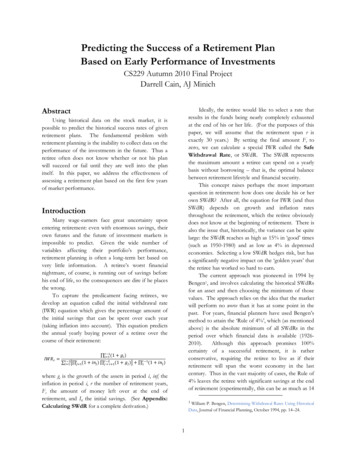
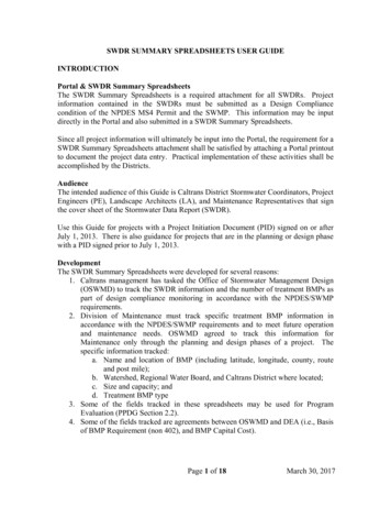
the project is grandfathered under the Caltrans Permit (Section E.2.d). This project issubject to the requirements contained within the 1999 Caltrans Permit.2. Treated Pervious Area (ac) must be within a TMDL watershed in order to be eligiblefor CUs. Treated Pervious Area (ac) is any pervious contributing drainage area(CDA) that is treated by a downstream treatment BMP. The treatment BMP footprintis included. A treatment BMP that treats a pervious area and possibly treats animpervious area within a TMDL watershed must calculate the amount of treatedimpervious area (if any) and treated pervious area separately. These areas must bereported in the TMT Spreadsheet. If this same treatment BMP is in a non-TMDLarea, only Treated Impervious Area (ac CT R/W) is required to be reported (to meetpost-construction treatment requirements).3. Stabilized Area (ac) must be within a TMDL watershed in order to be eligible forCUs.A Stabilized Area (ac) is any of the following: Pervious area that is unstable and is stabilized as part of a project’s disturbedsoil area are eligible for CUs if in a TMDL watershed (connection to upstreamimpervious area not required); Existing pervious area within the project limits that is already stable is noteligible for CUs (regardless of whether it is disturbed and re-stabilized or notdisturbed as part of the project).Examples of Stabilized Area (ac) include: RSP, slope paving, gabions, rock blanket,soils stabilized using Section II.D3 of the CGP (see PPDG 6.4.7.4 Validation of FinalSoil Stabilization), and DPPIA.4. Compliance Units (CUs) The Department must implement control measures to achieve 1650 CUs per year. One CU is equivalent to one acre of the Department’s right of way, from whichthe runoff is retained, treated, or otherwise controlled prior to discharge to therelevant reach. CUs must be reported in acres (ac). BMPs in TMDL watersheds may receive CUs for: That portion of the Treated Impervious Area that exceeds the PCTA; and Treated pervious areas (Treated Pervious Area (ac) and Stabilized Area(ac). No CUs or Alternative Compliance will be given to BMPs that only meet thePCTA.SWDR SPREADSHEET:This spreadsheet consists of 32 columns (Figure 1). Each column is identifiedwith a number, which can be cross referenced to where most of the informationcan be obtained in the SWDR (Figure 2 and 3).Page 4 of 18March 30, 2017
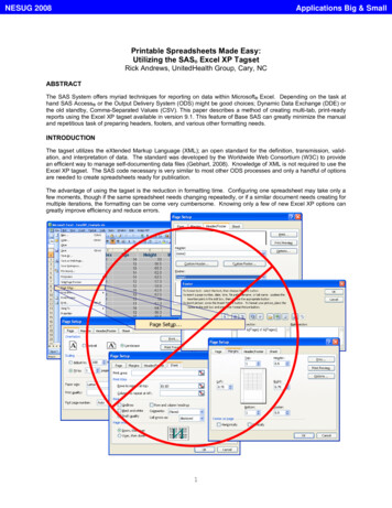
12345678910111213SWDRProject Project Long Risk DSA TMDLEA /County Route Beg PM End PMSigned DistrictDescription Phase SWDR Level (ac) WaterbodyProject tionGSRD TST MedFilter DPPIA SAStrips and nstSWMWELO RSAPerviousImperviousConst ConstArea (ac)AreaComment TreatmentArea (ac)Area (ac)Start CompBalance (ac)Area (ac)Figure 1: SWDR SpreadsheetUse either the Short or Long Form Cover Sheet (Figure 2 & 3) to fill out Columns1-12, 23, and 24 in the SWDR Spreadsheet. Depending on the project’s potentialto create stormwater impacts either a Short or Long Form SWDR is required. SeeAppendix E-2 and E-4 of the PPDG.Page 5 of 18March 30, 2017
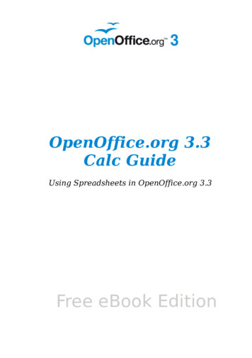
Figure 2: Short Form Cover SheetPage 6 of 18March 30, 2017
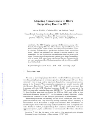
Figure 3: Long Form Cover SheetUse the Overall Project Treatment Summary Table (Figure 4) in Section 6 of theSWDR to fill out Columns 29-33 information in the SWDR Spreadsheet. VerifyColumn 29 matches the Long Form (Figure 3) and the Overall Project TreatmentSummary Table E-1 (Figure 4). For Table E-1 refer to Appendix E-8 of thePPDG.Page 7 of 18March 30, 2017
Figure 4: Overall Project Treatment Summary TableColumn Field Types:There are four field types that data can be entered. They are date, pull downmenu, number, and no restriction. There is one additional field type that data isautomatically entered. The tables below include an explanation of each field. Thefirst column is the identifier used in Figures 1-4.If additional clarification is required while filling out fields, use the SW Commentfield.Automatically filled in fields:These fields require no data to be entered. Data is automatically filled in.141516171819202122BiofiltrationStrips terDPPIASAOther BMPBiofiltration Strips and SwalesDetention BasinsInfiltration Basins and Infiltration TrenchesGross Solids Removal DevicesTraction Sand TrapsMedia FiltersDesign Pollution Prevention Infiltration AreasStabilized AreasOther BMPsPage 8 of 18March 30, 2017
Do not fill this field out. These fields are automatically calculatedusing the TMT spreadsheet to determine the number of each BMPused.27282930TreatedImperviousArea (ac)TreatedImperviousArea Balance(ac)TreatedPervious Area(ac)Stabilized Area(ac)Use Other BMP pull down menu for:o pilot and nonstandard treatment BMPs, ando Caltrans approved treatment BMPs that are rarelyused: Dry Weather Flow Diversion, Multi-ChamberTreatment Train (MCTT), and Wet BasinIf Other BMP pull down menu is used, insert BMP type(s) into theSW Comment field.Refer to Terms - Additional Tracking Information section of thisGuide.Do not fill this field out. This field is automatically calculatedusing the TMT spreadsheet. The Treated Impervious Area (ac CTR/W) column is used to sum all the TBMPs with these areas.Do not fill this field out. It is automatically calculated bysubtracting Column 27 from 26.If the project PID is signed before July 1, 2013, the followingapplies: PCTA NNI ATA 1, and It is not mandatory to treat PCTA because there are noAlternative Compliance requirements.Refer to Terms - Additional Tracking Information section of thisGuide.Do not fill this field out. This field is automatically calculatedusing the TMT spreadsheet. The Treated Pervious Area (ac CTR/W) column is used to sum all the TBMPs with these areas.Refer to Terms - Additional Tracking Information section of thisGuide.Do not fill this field out. This field is automatically calculatedusing the TMT spreadsheet. The Stabilized Area (ac) column isused to sum all the TBMPs with these areas.1Date fields:These fields require a valid date. If you try to enter anything else, you will get anerror message.This is the date when the District/Regional Design StormwaterSWDR SignedCoordinator signs the Cover Sheet of the SWDR. TheDateDistrict/Regional Design Stormwater Coordinator is always the lastto sign.Page 9 of 18March 30, 2017
23 Est.The estimated construction start date of the project.24 Est.The estimated construction completion date of the project.Const StartConst CompFields with pull downs:These fields have a built in pull down menu. Only valid data is entered. Thesepull downs are intended to help districts and project engineers enter the datacorrectly in a consistent format for future reference and compliance.24DistrictCounty5Route9Project Phase10 LongSWDR11 Risk Level13 TMDLWaterbody31 MWELO32 RSA2-DigitCaltrans County abbreviationIf the project is in multiple counties, select Var (various) from thepull down menu.If the project is in multiple routes, select Var (various) from the pulldown menu. If project is a non-highway project, use the nonhighway pull down menu.Use PID, PA/ED or PS&E.This is to see if the long or the short SWDR form was used; Yes (forlong) or No (for short).See Section 6.4.4.2 of the PPDG. Choose EW, WPCP, RL 1, RL 2,RL 3, or Special. Use EW for projects that are subject to the CGPand qualify for a Rainfall Erosivity Waiver. Use WPCP for projectsthat are exempt from the CGP and using a WPCP. Use Special forTahoe Basin and tribal land. Use the “SW Comment” field whenusing the Special pull down (e.g., Using EPA Permit because projectis on tribal lands).This field identifies if the project (or portion) is within a TotalMaximum Daily Load (TMDL) waterbody based on Appendix D ofthe June 2016 SWMP. Use the SW Portal to identify if the project islocated within a TMDL watershed based on Attachment IV ofCaltrans 2012 NPDES Permit. Answer “Yes” or “No”.This field identifies whether the Model Water Efficient LandscapeOrdinance (MWELO) applies. Select “Yes” or “No”. The DistrictLandscape Architect is responsible to ensure the project is compliantwith the Model Water Efficient Landscape Ordinance (MWELO)requirements included by California Department of Water Resourcesor local ordinance. Refer to Section 6.4.7.5 of the PPDG.Does the project require a Rapid Stability Assessment (RSA) perCaltrans Hydromodification Requirements Guidance? Answer “Yes”or “No”.Page 10 of 18March 30, 2017
Number fields:These fields are required to be in a numeric format. Some can be decimal butsome have to be whole numbers. Using less than or greater than signs or other textcharacter will result in an error message.1226DSA (ac)This field can be a decimal number. If no DSA, enter 0. Onedecimal place to the right is available. It is recommended to use 1at design and either 0 or 1 during planning. Use engineeringjudgment on significant figures to use.Refer to Terms - Additional Tracking Information section of thisPost ConstTreatment Area Guide.(ac)This field is the Post Construction Treatment Area. See Section 4.4of the PPDG. This field can be a decimal number. If no treatmentrequired, enter 0. Two decimal places to the right are available. Itis recommended to use 2 at design and 1 during planning.Fields with no restrictions:3EA / Project ID6Beg PM7End PMProjectDescription25 SW Comment8Add the 5 digit EA designation. If EAs are no longer accepted, usethe 10 digit EFIS Project ID. This field allows numeric and alphacharacters and must be filled out correctly. Caltrans is transitioningfrom EAs to Project IDs and this will satisfy the new requirement.If the project has only one continuous construction area (0.2 miles orgreater in length), type in the Begin post mile to match the Title Sheetof the plans. If the project has multiple construction areas, type in“Various”. If the project has only one project location (less than 0.2miles in length), use this field to report the post mile center location.If the project has only one continuous construction area, type in theEnd Post Mile to match the Title Sheet of the plans. If the project hasmultiple locations, type in “Various”.Brief description of the project.Applicable comments.Use the following text for projects that completed the PID phase priorto July 1, 2013: The PID for this project was signed onMM/DD/YYYY, and therefore the project is grandfathered under theCaltrans Permit (Section E.2.d). This project is subject to therequirements contained within the 1999 Caltrans Permit.If the PID is signed on or after July 1, 2013 the project must complywith the Project Planning and Design section requirements ofCaltrans 2012 MS4 Permit. This means following PCTArequirements per Section 4.4 of the PPDG. If the project PID issigned before July 1, 2013 the following applies:Page 11 of 18March 30, 2017
PCTA NNI ATA 1,It is not mandatory to treat PCTA because there are noAlternative Compliance requirements.Add text for Dry Weather FlowPage 12 of 18March 30, 2017
TMT SPREADSHEET:This spreadsheet consists of 25 columns (Figure 5). Each column is identifiedwith a number (top row), which can be cross referenced to the Column FieldTypes tables below.12345678910111213EA /BeginEndBeginEndBMPIDNO ProjectDistrict County Route LocBPM Latitude Longitude LocEPM Latitude Longitude acity(cyd)151617TreatedTreatedBMPImpervious PerviousSpecificArea (ac Area (acCommentsCT R/W) CT R/W)18192021222324Figure 5: TMT SpreadsheetColumn Field Types:There are four field types that data can be entered and explained below. They arepull down menu, number, no restriction, and currency. There is one additionalfield type that data is automatically entered. The tables below have three columns:column identifier (and can be cross referenced to Figure 5), column name (andcan be cross referenced to Figure 5), and a description.Do not fill this spreadsheet out if no treatment BMPs are proposed in the project.Fill out the TMT Spreadsheet only if treatment BMP(s) are required.If additional clarification is required while filling out fields, use the BMP SpecificComments field.Automatically filled in field:These fields require no data to be entered. Data is automatically filled in.1IDNO2EA / Project IDThis is the unique BMPs identifier. Do not fill this field out. It isautomatically filled in once the “EA / Project ID” cell is filled in onthe SWDR Spreadsheet. See Table E-2 in PPDG. This is the sameIDNO that Division of Maintenance uses in IMMS.This field is copied from the SWDR spreadsheet.Fields with pull downs:These fields have a built in pull down menu. Only valid data is entered. Thesepull downs are intended to help districts and project engineers enter the datacorrectly in a consistent format for future reference and compliance.3BMP Type25Basis ofBMPWQFWQVWaterBMPStabilized TMDLRWBCapitalCapacity CapacityshedRequirement Area (ac) WaterbodyCost(cfs)(cf)(non 402)See Fig. 6 below for types and brief description of each. Whenmultiple treatment BMPs are used in a treatment train the upstreamPage 13 of 18March 30, 2017
treatment BMP should be reported first followed by the nextdownstream treatment BMP, etc. Another possible methodwould be to put the primary first then next, etc It is up to thedistrict in methodology to use but should be consistent in reporting.4 District2-Digit5 CountyCaltrans County abbreviation (i.e., the counties in the pull downmenu will be based on the District chosen)6 RouteUse pull down menu and choose route for highway projects. Ifnon-highway project such as a Maintenance Facility, use FAC.Leave blank for any other type. For any non-highway project usethe BMP Specific Comments field for naming convention of nonhighway facility. The PE must coordinate with the designatedMaintenance Representative signing the SWDR for non-highwayfacility name.13 DirectionUse the side of the roadway the BMP is located and directiontraffic is headed on that side of the roadway. N, S, E, W. Use theofficial direction of the highway. For BMPs located on a connector,interchange, median, ramps or corner use the BMP SpecificComments field for clarification.22 TMDL Waterbody This field identifies if the treatment BMP is within a TotalMaximum Daily Load (TMDL) waterbody. If the TBMP is notwithin a TMDL area, then “Non-TMDL” is selected. The pulldown menu identifies the TMDL Waterbody (impaired waterbody)including the associated TMDLs (pollutants). Refer to Appendix Dof the June 2016 SWMP. The Portal automatically identifies thisinformation when the user enters a proposed BMP into the Portal.Use the Portal to identify the appropriate TMDL Waterbody pulldown information.25 RWBDetermine the Regional Water Board that the treatment BMP iswithin. This can be found using the Division of Maintenance is required to track this field based onCaltrans NPDES Permit.Number fields:These fields are required to be in a numeric format. Some can be decimal butsome have to be whole numbers. Using less than or greater than signs or other textcharacter will result in an error message.8Begin Latitude(d.d)This field is in decimal degrees. Use a minimum of 5 decimalplaces to the right.Every treatment BMP must have at least one lat. and long. BMPseasily identified in the field (e.g., basins and concrete vaultstructures), should have one entry at the center of the BMP.Longer BMPs or BMPs that may be difficult to locate in the futurePage 14 of 18March 30, 2017
(e.g., Biofiltration Strips and Swales, DPPIA, Infiltration Trench)should identify the beginning and end.9BeginLongitude (d.d)11End Latitude(d.d)12End Longitude(d.d)14Trash/SandCapacity (cyd)16TreatedImperviousArea (ac CTR/W)Use the BMP Specific Comment field if additional explanation isnecessary. The PE and Maintenance representative shouldcollaborate to determine best methodology to locate BMPs in thefield.This field is in decimal degrees and beginning of the BMP. Use aminimum of 5 decimal places to the right. Make sure to include thenegative sign.This field is in decimal degrees. Use a minimum of 5 decimalplaces to the right.Use the “BMP Specific Comment” field if additional explanation isnecessary. The PE and Maintenance representative shouldcollaborate to determine best methodology to locate BMPs in thefield.This field is in decimal degrees and end of the BMP. Use aminimum of 5 decimal places to the right. Make sure to include thenegative sign.Division of Maintenance is required to track capacity of a treatmentBMP that collects trash or traction sand. The intent of this field isto capture the capacity of a GSRD or a TST. Use the BMP SpecificComments field to include specific type of GSRD or TST (e.g.,Inclined Screen, Sand Vault, Loading Dock, Double Barrel, etc.).One decimal place to the right is available and recommended at allproject phases. Leave field blank if treatment BMP is not a GSRDor TST.Refer to Terms - Additional Tracking Information section of thisGuide.Use this field when designing treatment BMPs designed usingWQV or WQF. Use for treated impervious area inside Caltransright of way only. See Table E-2 in PPDG.It is recommended to use 2 digits to the right of the decimal point atdesign and 1 or 2 during planning.17TreatedPervious Area(ac CT R/W)Leave this field blank if treatment BMP is not designed usingWQV or WQF.Refer to Terms - Additional Tracking Information section of thisGuide.It is recommended to use 2 digits to the right of the decimal point atdesign and 1 or 2 during planning.Page 15 of 18March 30, 2017
181921WQV Capacity(cf)WQF Capacity(cfs)Stabilized Area(ac)Leave this field blank if treatment BMP is not designed usingWQV or WQF.Use this field for treatment BMPs designed using WQV. This isthe design WQV treated. Input as whole number.Use this field for treatment BMPs designed using WQF. This is thedesign WQF treated. Use 2 decimal places to the right.Refer to Terms - Additional Tracking Information section of thisGuide.Two decimal places to the right are available. It is recommended touse 2 at design and 1 or 2 during planning.WQV/WQF field is not required to be filled out for this BMPunless calculated amount is available.Fields with no restrictions:71015LocBPMLocEPMBMP SpecificCommentsBeginning post mile for the specific BMP. Use 3 decimal places tothe right. Can be used for documenting a treatment BMPs locationfor Annual Report or can be used for paddle marker location.For areas with several treatment BMPs clumped together the PEand Maintenance representative may decide to fill out the LocBPMfor the first BMP and the LocEPM of the last BMP. Any BMPs inbetween would not be filled out.Ending post mile for the specific BMP. Use 3 decimal places tothe right. Can be used for paddle marker location.For areas with several treatment BMPs clumped together the PEand Maintenance representative may decide to fill out the LocBPMfor the first BMP and the LocEPM of the last BMP. Any BMPs inbetween would not be filled out.Any applicable comments.Maintenance must have a good description of the size and locationof the treatment BMP. Refer to Figure 7 for example text.It is the responsibility of the PE to provide this description to theMaintenance Representative signing the SWDR.20Basis of BMPRequirementIt is the responsibility of the Maintenance Representative toultimately determine the final description that meets their needsand determine names for Maintenance Facilities.This field was created to track treatment BMPs required outside ofthe statewide NPDES Permit (e.g., 401 Certification). Use the BMPPage 16 of 18March 30, 2017
24(non 402)Specific Comments field for a brief explanation why it wasrequired.WatershedThis field is used to track the California watershed the treatmentBMP is within. Division of Maintenance is required to track thisinformation based on Caltrans NPDES Permit. If the WQPT(http://svctenvims.dot.ca.gov/wqpt/wqpt.aspx) is used to determinethe watershed, either the Calwater Watersheds layer or theWatershed Boundary Dataset layer can be used. Use the hydrologicsub area (HSA) name and #. (e.g. Angels Camp 534.22) If name isundefined then use undefined for name (e.g. undefined 535.80).Consult with the District/Regional NPDES Coordinator, if moreguidance is needed. The Water Quality Assessment Report(WQAR) prepared at PA/ED, if prepared, will have thisinformation also.Currency field:This field is formatted to currency.23 BMP CapitalCostThis field should be input as a whole number and the estimatedcost should be rounded to Caltrans standards. This field is onlyrequired at the PS&E Phase. Refer to Caltrans Design Guidancefor estimating costs captured for each treatment BMP.BMP Type pull down menu:BMP chGSRDTSTMedFilterDPPIADescriptionBiofiltration StripBiofiltration SwaleDetention BasinInfiltration BasinInfiltration TrenchGross Solids Removal Device (GSRD)Use the BMP Specific Comments field to capture the type(e.g., Inclined Screen or Linear Radial).Traction Sand TrapMedia Filter include Austin Sand Filter (earthen or vault),and Delaware Sand Filter. At this time any other mediafilter types should use "Other BMP". If a specific mediafilter type is required to remove a specific pollutant ofconcern, use the BMP Specific Comments field to includean explanation. Use the BMP Specific Comments field tocapture the type (e.g., Austin Sand Filter (earthen orvault), or Delaware.Design Pollution Prevention Infiltration AreaPage 17 of 18March 30, 2017
SARefer to Terms - Additional Tracking Information sectionof this Guide.Other BMPStabilized AreaUse for pilot and nonstandard treatment BMPs. InsertBMP type into BMP Specific Comments field.Also use “Other BMP” pull down menu for the followingCaltrans approved treatment BMPs that are rarely used:Dry Weather Flow Diversion, Multi-Chamber TreatmentTrain (MCTT), and Wet Basin. Insert BMP type intoBMP Specific Comments field.Figure 6: BMP Pull Down MenuFields with no restrictions (TMT Spreadsheet)BMP SpecificCommentsBiofiltration SwaleSize:Trapezoidal channel with 4:1 side slopesL 45’, W(at invert) 2’, Depth of Flow (at WQF) 0.13’Location:The center of the swale is located 12 to 20 feet from Caltransright of way.Austin Vault Sand FilterSizeL 152’, W 30’, Height(top of slab to top of wall) 6.5-10’LocationThe BMP is located between Loyal Road southbound onrampand I-5. A maintenance pullout has been provided on the eastside of the on ramp. Use the Begin Lat/Long provided for
Microsoft Excel software was used to develop the SWDR Summary Spreadsheets file. The file consists of two spreadsheets; the SWDR Spreadsheet tracks information related to the overall project and the Tracking Maintenance Treatment (TMT) Spreadsheet tracks the individual treatment BMPs. The Portal tracks additional information that the SWDR