Transcription
53-1002554-0122 August 2012 Brocade VDX 8770-4QuickStart Guide53-1002554-01*53-1002554-01*
Copyright 2012, Brocade Communications Systems, Incorporated.Brocade, Brocade Assurance, the B-wing symbol, BigIron, DCX, Fabric OS, FastIron, MLX, NetIron, SAN Health, ServerIron, TurboIron, VCS, and VDXare registered trademarks, and AnyIO, Brocade One, CloudPlex, Effortless Networking, ICX, NET Health, OpenScript, and The Effortless Networkare trademarks of Brocade Communications Systems, Inc., in the United States and/or in other countries. Other brands, products, or servicenames mentioned may be trademarks of their respective owners.Notice: This document is for informational purposes only and does not set forth any warranty, expressed or implied, concerning any equipment,equipment feature, or service offered or to be offered by Brocade. Brocade reserves the right to make changes to this document at any time,without notice, and assumes no responsibility for its use. This informational document describes features that may not be currently available.Contact a Brocade sales office for information on feature and product availability. Export of technical data contained in this document mayrequire an export license from the United States government.The authors and Brocade Communications Systems, Inc. shall have no liability or responsibility to any person or entity with respect to any loss,cost, liability, or damages arising from the information contained in this book or the computer programs that accompany it.The product described by this document may contain “open source” software covered by the GNU General Public License or other open sourcelicense agreements. To find out which open source software is included in Brocade products, view the licensing terms applicable to the opensource software, and obtain a copy of the programming source code, please visithttp://www.brocade.com/support/oscd.Brocade Communications Systems, IncorporatedCorporate and Latin American HeadquartersBrocade Communications Systems, Inc.130 Holger WaySan Jose, CA 95134Tel: 1-408-333-8000Fax: 1-408-333-8101E-mail: info@brocade.comAsia-Pacific HeadquartersBrocade Communications Systems China HK, Ltd.No. 1 Guanghua RoadChao Yang DistrictUnits 2718 and 2818Beijing 100020, ChinaTel: 8610 6588 8888Fax: 8610 6588 9999E-mail: china-info@brocade.comEuropean HeadquartersBrocade Communications Switzerland SàrlCentre SwissairTour B - 4ème étage29, Route de l'AéroportCase Postale 105CH-1215 Genève 15SwitzerlandTel: 41 22 799 5640Fax: 41 22 799 5641E-mail: emea-info@brocade.comAsia-Pacific HeadquartersBrocade Communications Systems Co., Ltd. (Shenzhen WFOE)Citic PlazaNo. 233 Tian He Road NorthUnit 1308 – 13th FloorGuangzhou, ChinaTel: 8620 3891 2000Fax: 8620 3891 2111E-mail: china-info@brocade.comDocument HistoryDocument TitlePublicationNumberSummary ofChangesPublicationDateBrocade VDX 8770-4 QuickStart Guide53-1002554-01New document.August 20122 of 32Brocade VDX 8770-4 QuickStart GuidePublication Number: 53-1002554-01
In this guide Introduction. . . . . . . . . . . . . . . . . . . . . . . . . . . . . . . . . . . . . . . . . . . . . . . . . . . . Safety notices . . . . . . . . . . . . . . . . . . . . . . . . . . . . . . . . . . . . . . . . . . . . . . . . . . Danger notices . . . . . . . . . . . . . . . . . . . . . . . . . . . . . . . . . . . . . . . . . . . . . . . . . Caution notices. . . . . . . . . . . . . . . . . . . . . . . . . . . . . . . . . . . . . . . . . . . . . . . . . ESD precautions . . . . . . . . . . . . . . . . . . . . . . . . . . . . . . . . . . . . . . . . . . . . . . . . Brocade VDX 8770-4, port side. . . . . . . . . . . . . . . . . . . . . . . . . . . . . . . . . . . . Brocade VDX 8770-4, nonport side . . . . . . . . . . . . . . . . . . . . . . . . . . . . . . . . Items included with the Brocade VDX 8770-4 . . . . . . . . . . . . . . . . . . . . . . . . Preparing for the Brocade VDX 8770-4 installation. . . . . . . . . . . . . . . . . . . . Unpacking and installing the Brocade VDX 8770-4. . . . . . . . . . . . . . . . . . . Port numbering. . . . . . . . . . . . . . . . . . . . . . . . . . . . . . . . . . . . . . . . . . . . . . . . Inserting a management module . . . . . . . . . . . . . . . . . . . . . . . . . . . . . . . . . Inserting a switch fabric module . . . . . . . . . . . . . . . . . . . . . . . . . . . . . . . . . . Inserting a line card . . . . . . . . . . . . . . . . . . . . . . . . . . . . . . . . . . . . . . . . . . . . Inserting power supplies . . . . . . . . . . . . . . . . . . . . . . . . . . . . . . . . . . . . . . . . Providing power to the Brocade VDX 8770-4 . . . . . . . . . . . . . . . . . . . . . . . . Preparing to configure the Brocade VDX 8770-4. . . . . . . . . . . . . . . . . . . . . Establishing a serial connection to the Brocade VDX 8770-4. . . . . . . . . . . Logging in to the serial console port. . . . . . . . . . . . . . . . . . . . . . . . . . . . . . . Changing the RBridge ID . . . . . . . . . . . . . . . . . . . . . . . . . . . . . . . . . . . . . . . . Assigning permanent passwords . . . . . . . . . . . . . . . . . . . . . . . . . . . . . . . . . Configuring the IP addresses . . . . . . . . . . . . . . . . . . . . . . . . . . . . . . . . . . . . Logging off the serial console port and disconnecting the serial cable . . . Establishing an Ethernet connection to the Brocade VDX 8770-4 . . . . . . . Customizing a host name . . . . . . . . . . . . . . . . . . . . . . . . . . . . . . . . . . . . . . . Customizing a switch name . . . . . . . . . . . . . . . . . . . . . . . . . . . . . . . . . . . . . . Setting the date and time . . . . . . . . . . . . . . . . . . . . . . . . . . . . . . . . . . . . . . . Determining installed software licenses. . . . . . . . . . . . . . . . . . . . . . . . . . . . Saving your changes . . . . . . . . . . . . . . . . . . . . . . . . . . . . . . . . . . . . . . . . . . . Verifying correct operation. . . . . . . . . . . . . . . . . . . . . . . . . . . . . . . . . . . . . . . Backing up the configuration . . . . . . . . . . . . . . . . . . . . . . . . . . . . . . . . . . . . Connecting network devices . . . . . . . . . . . . . . . . . . . . . . . . . . . . . . . . . . . . . Installing transceivers and attaching cables . . . . . . . . . . . . . . . . . . . . . . . . Managing cables . . . . . . . . . . . . . . . . . . . . . . . . . . . . . . . . . . . . . . . . . . . . . . Creating Brocade inter-switch link trunks. . . . . . . . . . . . . . . . . . . . . . . . . . .Brocade VDX 8770-4 QuickStart GuidePublication Number: 2425252628282929303031323 of 32
IntroductionYou can set up and install the Brocade VDX 8770-4 in the following ways: As a standalone unit on a flat surfaceIn a four-post rack with the Intake Duct KitIn a four-post rackIn a two-post telecommunications (Telco) rackThis manual describes how to set up the Brocade VDX 8770-4 as a standalone unit. For rack mount installationinstructions, refer to the manual that comes with the separately ordered rack kit.Table 1 describes the main installation and setup tasks, the estimated time required for each, and the itemsrequired to complete the task based on a fully populated Brocade VDX 8770-4 (192 10 GbE ports). Configurationswith fewer ports require less time. These time estimates assume a prepared installation site and appropriate powerand network connectivity.DANGERThe procedures in this manual are for qualified service personnel.TABLE 1Installation tasks, time, and items requiredInstallation taskTime estimateItems requiredSite preparation and unpacking BrocadeVDX 8770-430 minutes#2 Phillips screwdriver.Pallet jack.Hydraulic lift or assisted lift, able to raise to aminimum of 140 cm (55 in.), with a minimumcapacity of 113 kg (250 lb). A fully loadedversion of the Brocade VDX 8770-4 weighs86.18 kg (190 lbs).Installing the rack mount kit orintake duct rack mount kit30 minutesMounting and securing Brocade VDX8770-4 in the rack30 minutesRefer to the proper rack mount kit instructionsfor your specific rack.Inserting modules and power supplies5-10 minutes perunitManagement modules, switch fabric modules,line cards, power supplies (AC or DC).Installing power cables and powering onthe Brocade VDX 8770-420 minutesPower cables (provided in the Brocade VDX8770-4 accessory kit).Establishing a serial connection, logging onto the Brocade VDX 8770-4, andconfiguring the IP addresses20 minutesSerial cable (also called the console cable provided in the accessory kit).Workstation computer with a serial (console)port or terminal server port and a terminalemulator application (such as HyperTerminal).Ethernet IP addresses for the Brocade VDX8770-4 switch and for management modules:total two or three addresses, depending on thenumber of management modules installed.4 of 32Brocade VDX 8770-4 QuickStart GuidePublication Number: 53-1002554-01
TABLE 1Installation tasks, time, and items required (Continued)Installation taskTime estimateItems requiredInstalling an Ethernet cable, opening aTelnet session, and configuring theBrocade VDX 8770-4 date and time andadditional system parameters. Verify andback up configuration.20 minutesEthernet cabling (optional) for Telnet access.Refer to the Brocade Network OSAdministrator’s Guide.Installing transceivers as needed30-60 minutesCopper and optical transceivers anddirect-attach cables as needed.Attaching cables, cable ties, and cableguides2-3 hoursCables, cable ties, and cable managementfingers.CAUTIONThe Brocade VDX 8770-4 with DC power sources are intended for installation in restricted access areasonly. A restricted access area is a location where access can be gained only by service personnel throughthe use of a special tool, lock and key, or other means of security, and is controlled by the authorityresponsible for the location.CAUTIONThe Brocade VDX 8770-4 with AC power sources are intended for installation in restricted access areasonly. A restricted access area is a location where access can be gained only by service personnel throughthe use of a special tool, lock and key, or other means of security.Safety noticesWhen using this product, observe the danger, caution, and attention notices in this manual. The notices areaccompanied by symbols that represent the severity of the safety condition.NOTETranslated safety notices are in the Brocade Product Safety Notices publication, which is on the CD-ROM thataccompanies this product.The danger and caution notices are listed in numerical order based on their IDs, which are displayed in parentheses,for example (D004), at the end of each notice. Use this ID to locate the translations of these danger and cautionnotices in the Brocade Product Safety Notices.Brocade VDX 8770-4 QuickStart GuidePublication Number: 53-1002554-015 of 32
Danger noticesA danger notice calls attention to a situation that is potentially lethal or extremely hazardous to people. Alightning bolt symbol accompanies a danger notice to represent a dangerous electrical condition. Read andcomply with the following danger notice before installing or servicing this device.DANGERUse the supplied power cords. Ensure the facility power receptacle is the correct type, supplies therequired voltage, and is properly grounded. (D004)Caution noticesA caution notice calls attention to a situation that is potentially hazardous to people because of some existingcondition. Read and comply with the following caution notice before installing or servicing this device.CAUTIONUse safe lifting practices when moving the product. (C015)ESD precautionsThe Brocade VDX 8770-4 contains ESD-sensitive FRUs. When working with any Brocade VDX 8770-4 FRU, usecorrect electrostatic discharge (ESD) procedures. Wear a wrist grounding strap connected to chassis ground (if the Brocade VDX 8770-4 is plugged in) or abench ground. Refer to Figure 1 on page 7 for the location of the ESD jack. Store ESD-sensitive components in antistatic packaging.Brocade VDX 8770-4, port sideNOTEAirflow in the Brocade VDX 8770-4 is from the port side and left side (viewed from the port side) to the rear (fan side)of the switch.Figure 1 displays a sample configuration of the port side of the Brocade VDX 8770-4.6 of 32Brocade VDX 8770-4 QuickStart GuidePublication Number: 53-1002554-01
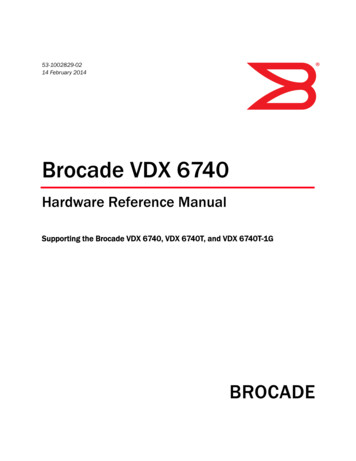
123456Management module slot 1Management module slot 2Switch fabric module slot 1Line card slot 1Line card slot 2Line card slot 3FIGURE 1789101112Line card slot 4Switch fabric module slot 2Switch fabric module slot 3Blank slot - unusedESD jackPower supplies (1-4, left to right)Port side of the Brocade VDX 8770-4 (sample configuration)Brocade VDX 8770-4, nonport sideFigure 2 displays a sample configuration of the nonport side view of the Brocade VDX 8770-4.Brocade VDX 8770-4 QuickStart GuidePublication Number: 53-1002554-017 of 32
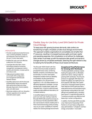
12Fan #1Fan #2FIGURE 23Ground lugNonport side of the Brocade VDX 8770-4 (sample configuration)Items included with the Brocade VDX 8770-4The Brocade VDX 8770-4 ships with the following items: Brocade VDX 8770-4 chassis, populated with: (management modules, switch fabric modules, and line cards areall packaged separately)-8 of 32Management modules (one)Switch fabric modules (up to three)Line cards (up to four)Filler panels for unoccupied slots for all modulesPower supplies (up to four)Power supply filler panels for unoccupied baysFan assemblies (two)Brocade VDX 8770-4 QuickStart GuidePublication Number: 53-1002554-01
Accessory kit containing the following items:- Console cable (RS-232 serial cable: The RS-232 cable has an adapter at one end that can be removed toprovide an RJ-45-style connector.)-Wrist strap (ESD grounding strap)Ground lug kitSFP extraction tool kitChina RoHS guideCable management finger assembliesBrocade-branded USB devicePower cord retainer kitBrocade VDX 8770-4 QuickStart Guide (this publication)Hardware for securing the switch in a rackWeb pointer documentAir filterThe rack mount kits must be ordered separately.Order the Brocade-branded transceivers (SFP, SFP , or QSFP) and cables or direct-attach cables from your Brocadedistributor. The Brocade VDX 8770-4 supports SR and LR SFP and SFP transceivers. The QSFP transceivers are SRtransceivers only.NOTEFor information about the transceivers that are qualified for the Brocade VDX 8770-4, refer ces/Brocade Compatibility Matrix.pdf.Preparing for the Brocade VDX 8770-4 installationNOTERefer to the safety notices before installation (“Safety notices”).Refer to “Power specifications” to plan for meeting power supply standards before installing the switch.Refer to “Environmental requirements” to plan for your environmental needs.Refer to “Managing cables” to plan for cable management.The following steps are required to ensure correct installation and operation.1. Provide a space that is 8 rack units (8U) high, 61.19 cm (24.09 in.) deep, and 43.74 cm (17.22 in.) wide. Onerack unit is equal to 4.45 cm (1.75 in.). If you are using the Air Intake Kit, you will need a space that is 10U highto accommodate both the Intake Kit and the switch.Plan to install the Brocade VDX 8770-4 with the port side facing the air-intake aisle. Airflow is from the left sideof the switch to the fan side. If you are using the Intake Air Duct rack kit for mounting the Brocade VDX 8770-4,then the airflow is from the port side to the fan side.Ensure that the rack is balanced and mechanically secured to provide stability in the event of an earthquakeand that the equipment does not exceed the rack’s weight limits.NOTEDoorways must be wider than 91 cm (36 in.) to accommodate the switch.Brocade VDX 8770-4 QuickStart GuidePublication Number: 53-1002554-019 of 32
2. Ensure that dedicated electrical branch circuits with the following characteristics are available: Up to four dedicated fused 200–240 VAC, 50–60 Hz feeds or -48 VDC (one per power supply) One cable for each power supplyCAUTIONUse a separate branch circuit for each AC power cord for redundancy in case one of the circuits fails. Protected by a circuit breaker in accordance with local electrical codesSupply circuit, line fusing, and wire size adequate to the electrical rating on the switch nameplateLocation close to the switch and easily accessibleGrounded outlets installed by a licensed electrician and compatible with the power cordsDANGERIf the installation requires a different power cord than the one supplied with the switch, make sure youuse a power cord displaying the mark of the safety agency that defines the regulations for power cords inyour country. The mark is your assurance that the power cord can be used safely with the switch.3. Plan for cable management before installing the switch.Cables can be managed in a variety of ways, such as by routing cables below the switch, to either side of theswitch, through cable channels on the sides of the rack, or by using patch panels.4. Ensure that the following items are available for configuration of the Brocade VDX 8770-4: Workstation with an installed terminal emulator, such as HyperTerminalConsole (serial) cable (provided)Ethernet cables (not provided)Either access to an FTP server or a Brocade USB device for backing up the switch configuration or collectingsupportsave output data (optional) Transceivers (copper and optical) and compatible cables and direct-attach cables if needed5. Ensure that the air intake and exhaust vents have a minimum of 5.1 cm (2 in.) of airspace.6. Ensure that the air temperature on the air intake side is less than 40 C (104 F) during operation.Power specificationsPower for the Brocade VDX 8770-4 can be supplied with either AC- or DC-based 3000 watt power supplies. TheBrocade VDX 8770-4 has room for up to four power supplies.Table 2 shows the basic power specifications for each power supply.10 of 32Brocade VDX 8770-4 QuickStart GuidePublication Number: 53-1002554-01
TABLE 2Power specifications.SpecificationValue for 3000W AC power supplyValue for 3000W DC power supplyInput rating16A70AInput voltage200–240 VAC, 50-60 Hz, 16.0 Ampmaximum-48 VDCOperating range180 ot 264 VAC-40 to -60 VDCInrush currentLimited to 60 Amp peak for any initialcurrent surge or spike of 10 ms or less ateither cold or warm start. Any additionalinrush current surges or spikes in the formof AC cycles or multiple AC cycles greaterthan 10 ms and less than 150 ms, must notexceed 25 Amp peak.Limited to 70 Amp peak for any initialcurrent surge or spike of 10 ms or less ateither cold or warm start.Output12 VDC, 245 Amps12 VDC, 245 AmpsCAUTIONFor the DC input circuit to the system of a Brocade VDX 8770-4 (3000W power supply), make sure thereis an 80 Amp circuit breaker, minimum -48 VDC, double pole, on the input lugs to the power supply. Theinput wiring for the connection to the switch should be copper wire, 2 American Wire Guage (AWG),marked VW-1, and rated minimum 90 C.The power requirements for a given switch configuration depend on which modules have been installed in theswitch. Table 3 shows the power consumption for the modules that can be used in the Brocade VDX 8770-4 switchalong with the power consumption for the cooling fans.All numbers for the line cards assume that the card is fully populated with optical transceivers, including QSFPs forthe 12x40 GbE line cards. All ports are Ethernet.You can calculate your power requirements by combining the power demands for the various modules and fan unitsin your configuration. While you may use fewer ports in a given line card, it is always safer to use the powerrequirement of a fully populated card.TABLE 3Power demands per componentModule or fan unitsPower demand at idle blades enabled, nooptics, ports disabled(Watts)Nominal power demand blades enabled, optics, 50%line rate, random packets(Watts)Maximum power demand - bladesenabled, optics, traffic present, full linerate, 64 byte smallest packet, 40 Cambient temp., maximum power for allsupported optics (Watts)Management module 464650Switch fabric module12012013248x1G line card24531046048x10G line card24531046012x40G line card247290440Fan unit2525268Brocade VDX 8770-4 QuickStart GuidePublication Number: 53-1002554-0111 of 32
CAUTIONFor the NEBS-compliant installation of a Brocade VDX 8770-4 with AC or DC systems, use a ground wireof at least 2 AWG. The ground wire should have an agency-approved crimped connector (provided withthe device) attached to one end, with the other end attached to building ground. The connector must becrimped with the proper tool, allowing it to be connected to both ground screws on the enclosure. Beforecrimping the ground wire into the provided ground lug, ensure that the bare copper wire has beencleaned and antioxidant is applied to the bare wire.Environmental requirementsDANGERDo not install the router in an environment where the operating ambient temperature mightexceed 40 C (104 F).Table 4 lists the environmental operating ranges for the Brocade VDX 8770-4. The requirements for non-operatingconditions are also provided for acceptable storage and transportation environments.TABLE 4Environmental requirementsConditionAcceptable range during operationAcceptable range during non-operationAmbient temperature0 to 40 C (32 to 104 F) outsideswitch-25 to 70 C (-13 to 158 F) outsideswitchHumidity5% to 90% RH noncondensing, at 40 C(104 F), with maximum gradient of 10%per hour10% to 90% RH noncondensing, at 70 C(158 F)Altitude0 to 3 km (10,000 ft.) above sea level0 to 12 km (40,000 ft.) above sea levelShock20G, 6 ms duration, half-sine wave33G, 11 ms duration, half-sine waveVibration0.5G p-p, 5-500 Hz at 1.0 octave/minute2.0G p-p, 5-500 Hz at 1.0 octave/minuteAirflowMaximum: 675 cu ft/min. (1147 cum/hr)Nominal: 200 cu ft/min. (340 cu m/hrNone requiredMaximum heatdissipationUp to 6000W or 20,500 BTU/hrNot applicableNOTEThe 0 to 40 C (32 to 104 F) range applies to the ambient air temperature at the air intake vents on the left side(as you face the port side) and port side of the Brocade VDX 8770-4.The temperature inside the Brocade VDX 8770-4 can be up to 90 C (194 F) for some modules during operation.Cooling policy is based on a combination of ambient temperature and measured temperature on the modules.Various combinations will result in an increase in fan speed to create more cooling in the switch.If a component approaches a critical temperature that will trigger a module shutdown, there will be a WARNINGmessage in the raslog, followed by a CRITICAL message saying that the module will shut down in two minutes.Use the show environment command to view temperature status.12 of 32Brocade VDX 8770-4 QuickStart GuidePublication Number: 53-1002554-01
Switch slotsSwitch slots are coded and numbered to differentiate between management module slots, switch fabric moduleslots, and line card slots. Management modules (MM) must be installed only in slots M1 and M2. Switch fabricmodules (SFM) must be installed only in slots S1 through S3. There must be at least one SFM installed in either slotS1 or slot S2. The line card slots, L1 through L4, can be filled with either 48x1G, 48x10G, or 12x40G line cards.Unused slots must be filled with the correct filler panels to maintain adequate cooling.Unpacking and installing the Brocade VDX 8770-4Use the following procedure to unpack and install your Brocade VDX 8770-4.CAUTIONUse safe lifting practices when moving the product. (C015)NOTEA fully populated Brocade VDX 8770-4 weighs approximately 86.18 kg (190 lb) and requires a hydraulic or assistedlift to install it.1. Unpack the Brocade VDX 8770-4.a.Cut the bands that encircle the packaging.b.Slide the upper portion of the cardboard shipping box up off the pallet and shipping tray.NOTEThe Brocade VDX 8770-4 packaging incorporates a wood pallet and brackets. The switch sits on top of acorrugated cardboard shipping tray.c.Save the packing materials for use when returning a switch.d.Leave the switch on top of the shipping tray and pallet if the switch must be transported to the installationlocation.2. Use a pallet jack or other assisted lift to transport the new switch to the installation area.3. Using the rack mount instructions, install the rack components in the rack and mounting flanges on the switch.The rack mount kit and instructions are shipped separately from the switch.4. Remove the accessory kit (cardboard box), packing foam, and antistatic plastic from the switch and set themaside.5. Remove the foam inserts around the base of the switch.6. Use a lift to raise the switch to the correct level. If installing the switch in a rack, follow the instructions providedby the rack kit manufacturer.7.If applicable, lock the wheels of the lift.8. Ensure that the switch is oriented so that the left side and port side (front) have access to intake air.9. Gently slide the switch onto the final installation surface, ensuring that it remains supported during the transfer.Brocade VDX 8770-4 QuickStart GuidePublication Number: 53-1002554-0113 of 32
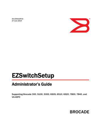
10. Before you apply power to the switch, you can install the MM, SFM, and line card modules as well as powersupplies to speed up your installation. Refer to the following tasks for information on inserting thet variousmodules.Port numberingThe Brocade VDX 8770-4 uses the following port numbering method: 12x40G line card module — Ports are numbered from 1 through 12 from from left to right when installed in theswitch. Refer to Figure 3.FIGURE 312x40G line card 48x1G and 48x10G line card modules — Ports are numbered from 1 through 48, from left to right, with theodd-numbered ports on the upper row and the even-numbered ports on the lower row when installed in theswitch. Refer to Figure 4.FIGURE 448x10G line card (48x1G line card similar)Inserting a management moduleFor this procedure, refer to “ESD precautions” and Figure 5.Complete the following steps to insert an MM.1. Unpack the new MM and remove it from the anti-static bag.2. Inspect the module for damage.3. Remove the protective caps from the b ackplane connectors.4. Rotate the ejectors toward the center of the module.5. Align the module pan with the guides in the slot. The first MM should be installed in slot M1.6. Slide the MM into the slot until it is firmly seated.7.Rotate the ejectors away from the center of the module face until the module is tight in the slot.8. Tighten the captive screws using the Phillips screwdriver.14 of 32Brocade VDX 8770-4 QuickStart GuidePublication Number: 53-1002554-01
FIGURE 5Inserting a management moduleInserting a switch fabric moduleFor this procedure, refer to “ESD precautions” and Figure 6.Complete the following steps to insert the SFM.1. Unpack the new SFM and remove it from the anti-static bag.2. Inspect the module for damage.3. Remove the protective caps from the backplane connectors.4. Unscrew the power enable pin, pull it outward, and move the slider toward the center of the module face.5. Open the ejectors on the new SFM by rotating them toward the center of the module face. Orient the switchfabric module so that the ejectors are toward you.6. Align the module pan with the guides in the slot. The first SFM ashould be installed in slot S1.7.Push the SFM firmly into the slot.8. Close the ejectors by rotating them away from the center of the SFM. The levering action of the ejectors seatsthe module in the slot.9. Tighten the captive screws using the Phillips screwdriver.10. Pull out the power enable pin and move the slider all the way to the right.11. Screw in the power enable pin.12. Tighten the screws on the slider.Brocade VDX 8770-4 QuickStart GuidePublication Number: 53-1002554-0115 of 32
FIGURE 6Inserting a switch fabric moduleInserting a line cardFor this procedure, refer to “ESD precautions” and Figure 7.Complete this procedure to insert a new line card.1. Unpack the new line card and remove it from the anti-static bag.2. Inspect the module for damage.3. Remove the protective covers from the backplane connectors.4. Orient the line card so that the ports are at the front of the switch. The component side of the card should faceup.5. Open the ejectors by rotating them toward the center of the line card face and align the flat side of the line cardinside the left and right rail guides in the slot. Line cards can be inserted in any of the slots labelled L1 throughL4.6. Slide the line card all the way into the slot.7.Close the ejectors by rotating them away from the center of the line card. The levering action of the ejectorsseats the line card in the slot.8. Tighten the captive screws using the Phillips screwdriver.16 of 32Brocade VDX 8770-4 QuickStart GuidePublication Number: 53-1002554-01
FIGURE 7Inserting a line card (48x10G card shown)Inserting power suppliesThe switch can be powered with either AC or DC power supplies. They are slightly different in appearance and in theway that the power cord is attached. Follow the procedure below for your type of power supply.Brocade VDX 8770-4 QuickStart GuidePublication Number: 53-1002554-0117 of 32
FIGURE 8Inserting a power supplyInserting an AC power supplyFor this procedure, refer to “ESD precautions” and Figure 8.To replace a power supply, complete the following steps.DANGERHigh Touch Current. Earth connection is essential before connecting the power supply.1. Unpack the new power supply and remove it from the anti-static bag.2. Inspect the power supply for damage.3. Ensure that the handle of the replacement power supply is pushed down.4. Insert the power supply into the slot.5. Rotate the handle upward to fully seat the power supply.6. Tighten the captive screw.Inserting a DC power supplyFor this procedure, refer to “ESD precautions” and Figure 8.18 of 32Brocade VDX 8770-4 QuickStart GuidePublication Number: 53-1002554-01
To replace a DC power supply, complete the following steps.1. Unpack the new power s
To find out which open source software is included in Brocade products, view the licensing terms applicable to the open source software, and obtain a copy of the programming source code, please visit . Brocade VDX 8770-4 chassis, populated with: (management modules, switch fabric modules, and line cards are all packaged separately)