Transcription
by Thomas Henrygood quality power supply is essentialfor homemade electronic music equipment. And yet, do-it-yourselfers oftengive short shrift to this important module. The general attitude seems to bethat the power supply is an annoyance;you’ve got to have one, but since it doesn’t make anyneat sounds, it frequently fails to get the attention itdeserves.This article addresses the problem by explainingwhy, in fact, power supplies are crucial to good performance from electronic music equipment. It thengoes on to show you how to construct your own.Actually, kit companies haven’t helped the situation much. Many of the power supply kits currently available are lacking in one regard or another. Forexample, at the time of this writing, one companyoffers a bipolar power supply which isn’t even regulated, while another lists a regulated one, but theavailable current is minuscule. Build your ownpower supply and you can easily overcome thesehurdles!APower Supplies forElectronic MusicDESIRABLE FEATURESPower supplies for electronic music should beregulated and there are several good reasons why.First, hum caused by supply ripple is nipped in thebud. Since the regulator clamps the filtered DC to afixed level, any residual bumps are neatly truncated.Next, the output voltage will remain relativelystable, even if you start adding more modules toyour system. (Most homemade music equipment ismodular in nature, with all of the individual circuitsbeing powered by a main supply.)Another advantage to regulation relates specifically to voltage-controlled oscillators (VCOs) used inmusic synthesizers. By powering the VCO from a regulated supply, you can be sure that the tuning won’tdrift all over the place. This will keep your listenersfrom having to suffer through “clinkers” or sournotes!Finally, regulated supplies typically have a greatdeal of safety protection built into them. With a mod-ern design, it is possible to guard against input or output short circuits, as well as overheating.With regard to current, a decent power supplyshould be able to provide at least a half amp or so oneach output. As hinted at above, a modular systemmay consist of a dozen or more separate circuits, eachFigure 1A Bipolar 15V PowerSupply.Nuts & Volts Magazine/January 19987
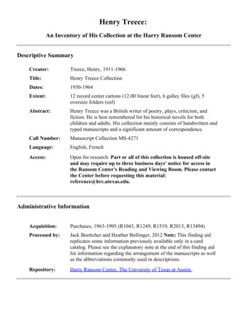
Figure 2A 5V PowerSupply.Figure 3Modification for aCombined PowerSupply.one drawing current from the supply. The idea here,then, is to build a power supply once making sure thatit has enough beef to handle a number of modules.What voltages are needed for electronic musicdevices? Well, for analog circuitry, history has shownthat a bipolar 15V supply is best for a variety of reasons. Perhaps the most important is that many of theclassic special-purpose synthesizer chips require this. Itis not uncommon to encounter music ICs which operate only on a bipolar 15V, or perhaps just a single 15Vline. But even for discrete or homebrew op-ampdesigns, these voltages are a good choice.Here’s why. By using a bipolar 15V instead of, say,a bipolar 9V supply, you attain much greater headroomthroughout the circuit before clipping occurs. In audiocircuitry, as a general rule, the greater the headroom,the better the distortion and noise figures will be.It’s no secret that modern music is being invaded bymicroprocessors. Hence, it would be wise to also have asource of 5V available. This is a pretty standard voltagefor most microprocessors, as well as TTL circuits.We can put these factors all together to come upwith a design plan. We will shoot for a regulatedpower supply, capable of providing 15V, -15V, and 5V, with 0.75 amps available from each line.Moreover, we will demand excellent safety requirements like short circuit and overheating protection.These goals are easily met with just a tad of care. So,let’s see what it takes.DESIGN ANALYSISRefer to Figure 1 which shows the schematic of abipolar 15V power supply. A standard 110V AC entersthe circuit from the left, via wall plug P1 and an 18gauge line cord. This passes through the main powerswitch, S1. More importantly, it also goes to fuse F1.A fuse is essential not just for your safety, but alsofor the well-being of any other gear connected. By theway, this is a 1A fast blow fuse, but we’ll wait just a bitbefore seeing how that value was arrived at.T1 is a 36V center-tapped transformer rated at1.5A. Theoretically, since we’ll be using a bridge rectifier arrangement across the entire secondary, weshould be able to draw 1.5A from both the 15V and-15V sides.However, we’ll introduce a good safety marginhere by specifying the supply as 0.75A per side. Thisputs less stress on the transformer, permitting it to runcooler and you to breathe easier.The bridge rectifier composed of D1 through D4creates pulsating DC voltages of both positive and negative polarities. These two voltages will be referencedto the ground established by the center tap of T1’s secondary.Figure 41:1 Foil Side Artwork8January 1998/Nuts & Volts Magazine
Figure 5Parts PlacementGuide.Notice that the bridge implements fullwave rectification. This isan extremely efficient approach,since both the positive and negative portions of the AC input areused. Also, the pulsating DC willhave a frequency of 120 Hz now(twice the 60 Hz input) which iseasier to filter.By the way, all of the rectifiersin this circuit should be rated for apeak inverse voltage of at least100V and a current capability of1A. The 1N4002 is a good choicehere. The positive output is foundat the junction of D1 and D3. Thisis applied to filter capacitor C3.Most text books have standard formulas for determining theoptimal value of power supply filtercapacitors; it turns out that 1000mfd works well here. But watchthe voltage rating! The capacitor will store the peakvalue of the pulsating DC which, in the worst case, willbe about 25V. Thus, for a good margin of safety,choose C3 to have a working voltage of double that.(Curious about that 25V? Well, transformers are ratedin volts RMS; multiply this by 1.414 to determine thepeak voltage. Doing so shows you that T1 will generate a peak voltage of about 50V. Divide that by two toget the value for each half of the secondary.)The next step is to regulate the voltage on C3 andthat’s the purpose of IC1, the well-known 7815. Theinput voltage to this chip should be higher than thedesired output voltage. If the input is too low, say 18Vor below, then you’ll drop out of regulation. And if it’stoo high, then the regulator will run hot. (Essentially,Figure 7 -may be (as long as it’s reasonably close to 15V).The input and output pins of IC1 should be stabilized, especially if there’s any messy wiring leading upto them. So, it’s generally a wise idea to attach bypasscapacitors very close to the pins.Since we’ll probably be building this on a printedcircuit board (which is inherently tidy), and will locateC3 close to IC1, there’s really no need for a cap on theinput. However, the output could be feeding a varietyof other modules through a tangle of wires. So we’lltack on capacitor C1 to the output pin. This willimprove the transient response of the chip.The 7815 regulator is pretty neat in that it hassome internal protection circuitry. If the IC overheatsfor any reason, it simply shuts itself down until the con-slipped with a pair of pliers. Inthat brief instant of time, theoutput voltage of IC1 will behigher than the input which isnow at 0V due to the shortacross C3. And that’s all ittakes to fry the chip!However, notice rectifierD5. Normally, this will bereverse-biased and just sitsthere doing nothing. But, ifthat slip of the pliers reallyhappens, then the cathodedrops to 0V. The rectifier goesinto forward bias and clampsFigure 6A multiple isnothing morethan several jackswired in parallel.Acting like a “Ycord,” it’s a utilitydevice that letsyou split a singlepatch cord intoseveral outputs.There is room fortwo of these (fourjacks each) on the1U rack panelfronting thepower supply.The switch, LED, and fuse for the power supply fit behind a standard 1U rack panel, leaving plenty of room for two multiples.Figure 8Drilling Guide for the 1U Rack Panel.the 7815 “throws away” any excess energy in theform of heat.) Of course, the voltage on C3 fluctuates as the output load changes, but typically will liebetween 20V and 25V. Even though the input is moving about, the output will hold rock solid thanks to the7815.By the way, don’t be surprised if the output of IC1doesn’t hit 15V on the button. According to the manufacturer’s spec sheet, the output for a given 7815may lie anywhere between 14.4V and 15.6V. Thisdoesn’t matter, in general. What’s important is thatthe output be locked into some voltage whatever itAll dimensions in inches.dition is corrected. Notice that this covers output shortcircuits as well.And speaking of heat, it is essential that IC1 (andthe other two voltage regulators mentioned in this article) be properly heatsinked. That extra surface areareally helps to keep things cool!But there are two other ways we can easily augment the protection. For starters, imagine that filtercap C3 is accidentally shorted to ground. Maybe awasher rattled loose inside the cabinet, or perhaps youthe output to more or less the same level as theinput. To put it another way, it is now impossiblefor the input of IC1 to ever drop substantially lowerthan the output.D6 performs another useful task. Its purpose is toensure that the output line feeding all of the othermodules can never go negative. Of course, this wouldnormally be impossible. But imagine that some othermodule in your system goes haywire or that you accidentally cross the supply lines in some fashion. D6snaps to attention and safely dumps the negative voltage to ground.Nuts & Volts Magazine/January 1998 9
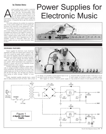
Pause for a moment to really consider what wehave accomplished so far. We now have a decent regulated 15V at our disposal, and it can handle a whopping 0.75A. Overheating and output short circuits areno longer part of our nightmares. And best of all,we’ve protected the supply itself, as well as any otherpotentially expensive equipment in our system.With just a little extra care, we have truly come upwith a platinum power supply!Generating a -15V is just as easy, if you keep a fewsimple component orientations in mind. Refer again toFigure 1. The junction of D2 and D4 spits out a negative pulsating DC voltage. This is filtered by C4 andthen tamed by IC2, the 7915 negative voltage regulator. C2 then stabilizes the output of the regulator.However, observe carefully the polarities of both C2and C4; they’re the reverse of what appeared in thedescription for the positive supply. D7 and D8 providegoof-proofing, but again notice how the orientation isflipped here. An easily missed point is that the 7815and 7915 regulators have different pinouts. Keep thisin mind, unless you enjoy fireworks!A panel LED is always nice to give visual indicationthat the circuit is on. This is the purpose of D9 and itscurrent limiting resistor R1. Incidentally, in most electronic music equipment, the positive supply gets moreof a workout than the negative. So, we put the LED onthe -15V side just to even things out a trifle.BIPOLAR 15V POWER SUPPLYResistorR1 1.5K, 1/4WNow about that fuse, F1. Its value depends on thetotal power dissipated by the circuit. Recall that someof this power will be in the output of the supply, butsome will also be in the heat generated by the regulators. And then we have to allow for losses in the transformer, as well as the rectifiers.We don’t have to be slavish about this, so a quickestimation shows that the bipolar power supply mightdraw as much as 60 watts. This suggests a total current drain of 0.5A (60W divided by 120V).To avoid blowing fuses repeatedly, and yet providegood protection from serious conditions, we’ll doublethis to arrive at a final suggested rating of 1A.As mentioned earlier, if you plan on using anymicroprocessor or TTL circuitry in your rig, then you willdefinitely want to have a source of 5V. We can usemany of the same techniques to carry out this plan.Refer to Figure 2 now.The line voltage is applied to T1 by way of switchS1 and fuse F1. In this case, F1 is a 1/2A fast blowtype. sT1 is a 9V transformer, rated at 1A. As usual,we’ll derate things a bit just to permit a decent safetyfactor. So, instead of turning this circuit into a toasteroven, we’ll specify the maximum output current at0.75A. For best efficiency, a bridge rectifier arrangement is used again. But since we’re only creating a single supply voltage ( 5V), the transformer doesn’t needa center tap on the secondary. Instead, the junction ofPARTS LISTCapacitorsC1, C2 10 mfd, 25V electrolyticC3, C4 1000 mfd, 50V electrolyticSemiconductorsD1 - D8 1N4002 rectifierD9 Red LEDIC1 7815 voltage regulatorIC2 7915 voltage regulatorOther ComponentsT1 36VCT, 1.5A transformerS1 SPST heavy duty toggle switchF1 A fast blow fuseP1 18 gauge line cord with plugMiscellaneousPrinted circuit board, heatsinks, panel mount fuseholder, heat shrink tubing, LED clip, #4 hardware(nuts, bolts, lock washers), wire, heatsink grease,solder, etc. 5V POWER SUPPLYResistorR1470 ohms, 1/4WCapacitorsC110mfd, 25V electrolyticC22200mfd, 25V electrolyticSemiconductorsD1 - D6 1N4002 rectifierD7red LEDIC17805 voltage regulatorOther ComponentsT19V, 1A transformerS1SPST heavy duty toggle switchF11/2A fast blow fuseP118 gauge line cord with plugMiscellaneousPrinted circuit board, heatsink, panel mount fuseholder, heat shrink tubing, LED clip, #4 hardware(nuts, bolts, lock washers), wire, heatsink grease,solder, etc.10January 1998/Nuts & Volts MagazineORDERING INFORMATIONThe following kits are available from MidwestAnalog Products: 5V Power Supply — Kit of parts includes anAssembly Guide and all items mentioned in theParts List except heatsink grease and solder. PartNumber PPS-1, 24.95 (plus 3.00 shipping andhandling).Bipolar 15V Power Supply — Kit of parts includes anAssembly Guide and all items mentioned in theParts List except heatsink grease and solder. PartNumber PP2-1, 39.95 (plus 4.00 shipping andhandling).Combo Power Supply — Includes both kits ( 5V andBipolar 15V) as described above. Part Number PPS3, 59.95 (plus 6.00 shipping and handling).Blank Rack Panel Kit — includes an unfinished 13/4” by 19” by 1/8” aluminum panel, angles, andhardware for mounting a circuit board, and instructions on how to drill, cut, and work with rack panels. Part Number K901, 8.95 (plus 3.00 shippingand handling).Shipping is by First Class Mail. Prices shown in USdollars. Remit US funds only. Write for shippinginformation to other countries. MN residents add6.5% sales tax. Money orders and checks only.Prices and terms subject to change without notice.Order from:Midwest Analog ProductsP.O. Box 2101North Mankato, MN 56003E-Mail: map@prairie.lakes.comWWW: http://prairie.lakes.com/ mapD2 and D4 creates the ground reference.The positive pulsating DC voltage at the tie pointof D1 and D3 feeds into filter capacitor C2. The voltageon C2 will vary from about 10V to 13V, dependingon the load conditions. A few standard calculationscome up with a value of 2200 mfd at 25V for thiscapacitor (once more allowing for a margin of safety).If a clean printed circuit board pattern is used, andC2 is kept close to the regulator, then no bypass capacitor should be needed on the input pin of IC1. But wedefinitely want to stabilize the output a bit, and that isthe purpose of C1.And always mindful of things that can go wrong,we plop in D5 and D6 to guard against nasty voltagereversals and short circuits. Finally, panel LED D7 provides visual indication that the unit has been energized.It is highly likely that you will want both a 5Vand a bipolar 15V power supply in your electronicmusic rig.In this case, refer to Figure 3 which shows how tocombine them. Essentially, you simply parallel the primaries of the two transformers, eliminating the redundant switch, fuse, and line cord. Notice, though, thatthe fuse should now be rated at 1.5A to cover bothsupplies. Finally, you can ax one of the LEDs, if desired.BUILDING YOUR OWN POWER SUPPLYCAUTION: Power supplies, like this circuit, use110V AC which can be dangerous and even lethal!Do not attempt this project unless you are skilledat working with 110V AC.Let’s assume that you want to build both powersupplies mentioned above and house them as a singleunit. To simplify things, we’ll juxtapose the two circuitboards in the illustrations. Refer to Figure 4 whichshows the foil side artwork for the joint project.Obviously, if you only need one or the other, simplydelete the unwanted portion. If you enjoy etchingprinted circuit boards, then have at it!On the other hand, if you would just as soon avoidmessing about with chemicals and wish to simplify thetask of locating all of the components, then check theParts List for kit availability via mail order.There are three interesting things to notice aboutthe printed circuit board. First, observe how fat thetraces are; this not only permits greater current flow,but also helps draw heat away from the rectifiers.Next, three large pads stand out from the rest.These are drilled to a 1/8” diameter, which then permits you to secure the heatsinks to the board with #4machine bolts and nuts. Lastly, the various outputs feature a large number of paralleled pads for powering amultitude of modules.Now, you’ll have to take care of running down allof the parts. Most of these are easy to find, but the36VCT transformer rated at 1.5A might take some digging in the catalogs. Even though this is a standardsize, it isn’t nearly as common as the “filament” types.And when you do find it, don’t be surprised at thecost! These are always fairly expensive, but keep inmind that you’ll only need one to handle quite a fewmodules in your system.When you’re shopping, don’t forget the nicetieslike heat shrink tubing, tie bands, panel mount fuseholder, hefty power switch, line cord, etc. In particular,you’ll want to be especially mindful of how you’regoing to handle the 110V AC side of things.Remember the cardinal rule: All joints carrying110V AC must be completely covered and insulated! If you’re ready to build, then refer to Figure 5which shows the parts placement guide for the printedcircuit board. This is pretty straightforward. But hereare a few tips to help you along.When loading the board, take great pains to seethat you orient the capacitors and rectifiers properly.And don’t forget that there is one jumper on the
board. This is denoted by the letter “J.” You can use aleftover snippet of a rectifier lead to form the jumper.Before soldering any one of the three regulators inplace, smear a thin layer of heatsink grease across theunderside. (Small, inexpensive tubes of heatsink greaseare readily available at your local Radio Shack.) Thenbolt the regulator to its heatsink. It probably ought tobe said for emphasis: In order to draw the requisite0.75A from each line of the power supply, heatsinksand heatsink grease are mandatory.With regard to how the transformer secondariesattach to the board, consider the bipolar supply first.Two of the pads are marked “SEC;” these connect tothe outer legs of the secondary winding. The third paddenoted “CT” attaches to the secondary’s centertap.The 5V supply is simpler; just connect up the twosecondary lines (in either order) to the pads marked“SEC.”Finally, the anodes and cathodes of LEDs D7 andD9 are called out on the parts placement guide by theletters “a” and “c,” respectively.Apart from making sure that you’ve left ampleroom for air flow and that none of the 110V AC con-nections can come in contact with the remaining circuitry, it really doesn’t matter how you mount orenclose the power supply. Most musicians prefer to userack-mounted equipment. In this case, you would installthe power supply at the bottom of your cabinet, so thatthe heavy transformers can be bolted to its floor.Now power supplies don’t require much in theway of front panel real estate; room for a switch, afuse holder, and an LED is about all it takes.It’s a shame to waste any of the remaining surfacearea, so you might want to consider adding in somesimple utility options. One of the most useful is a “multiple.” This is nothing more than a bunch of jacks thathave been wired in parallel, sort of like a rack-mounted“Y-cord.” See Figure 6. Multiples are extremely handyin the studio, since they allow you to drive several different devices from a single source.If this approach appeals to you, then refer toFigure 7 which illustrates one possible layout.Everything fits readily behind a standard 1U panel (13/4” by 19”).Figure 8 shows the associated drilling guide. Theprinted circuit board mounts behind the completedpanel on little angles, secured in place by some #4bolts, lock washers, and nuts.CHECKING THINGS OUTAnd that’s it! There are no adjustments to bemade before using your new power supply. But dotake a few extra moments to inspect your handiworkonce more before you first plug it in.If everything looks hunky-dory, take the plungeand fire up the circuit. Assuming you successfully passthe smoke test, get out your multimeter and verify thatyou have voltages reasonably close to 15V,-15V, and 5V available.While this may have seemed a bit of detour fromyour usual activity of creating cool sounds, it will haveall been worth it. For you now have the confidencethat your valuable music gear is being powered by astable and steadfast unit. And, with a full 0.75A available on each of the three lines, you shouldn’t have tobuild another power supply for quite some time. So,start hooking up your sound modules and get back todoing what you like best: making music! NVAD HERENuts & Volts Magazine/January 199811
good quality power supply is essentialfor homemade electronic music equip-ment. And yet, do-it-yourselfers often give short shrift to this important mod-ule. The general attitude seems to be that the power supply is an annoyance; you've got to have one, but since it doesn't make any neat sounds, it frequently fails to get the attention it .