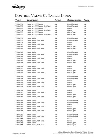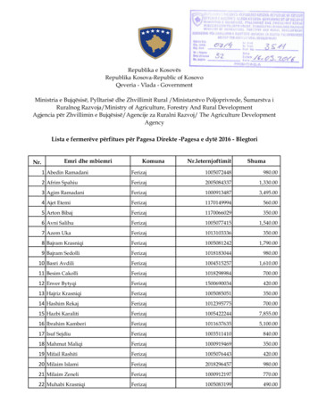
Transcription
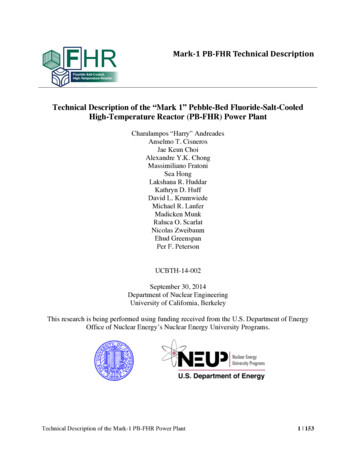
Mark- ‐1PB- ‐FHRTechnicalDescriptionTechnical Description of the “Mark 1” Pebble-Bed Fluoride-Salt-CooledHigh-Temperature Reactor (PB-FHR) Power PlantCharalampos “Harry” AndreadesAnselmo T. CisnerosJae Keun ChoiAlexandre Y.K. ChongMassimiliano FratoniSea HongLakshana R. HuddarKathryn D. HuffDavid L. KrumwiedeMichael R. LauferMadicken MunkRaluca O. ScarlatNicolas ZweibaumEhud GreenspanPer F. PetersonUCBTH-14-002September 30, 2014Department of Nuclear EngineeringUniversity of California, BerkeleyThis research is being performed using funding received from the U.S. Department of EnergyOffice of Nuclear Energy’s Nuclear Energy University Programs.Technical Description of the Mark-1 PB-FHR Power Plant1 153
Executive SummaryThis report describes the results of work at the University of California, Berkeley (UCB) todevelop an initial pre-conceptual design for a small, modular 236-MWth pebble-bed fluoridesalt-cooled, high-temperature reactor (PB-FHR). This design study contributes to a larger U.S.Department of Energy Integrated Research Project (IRP) collaboration with the MassachusettsInstitute of Technology and the University of Wisconsin, Madison to establish the technical basisto design, license, and commercially deploy FHRs.The Mark-1 (Mk1) PB-FHR design described here differs from previous FHR designsdeveloped and published by UCB and others. It uses a nuclear air-Brayton combined cycle(NACC) based upon a modified General Electric 7FB gas turbine, designed to produce 100MWe of base-load electricity when operated with only nuclear heat, and to increase this poweroutput to 242 MWe using gas co-firing for peak electricity generation. Due to the high thermalefficiency of the NACC system, the steam-bottoming condenser of the Mk1 PB-FHR requiresonly 40% of the cooling water supply that is required for a conventional light water rector(LWR), for each MWh of base-load generation. As with conventional natural-gas combinedcycle (NGCC) plants, this makes the efficiency penalty of using dry cooling with air-cooledcondensers much smaller, enabling economic operation in regions where water is scarce.The primary purpose of the Mk1 design, with its co-firing capability, is to provide a newvalue proposition for nuclear power. The new value proposition for NACC arises fromadditional revenues earned by providing flexible grid support services to handle the everincreasing demand for dispatchable peak power, in addition to traditional base-load electricalpower generation. Because under base-load operation NACC power conversion has lower fuelcosts than NGCC, and under peaking operation has higher efficiency in converting natural gas toelectricity than NGCC, NACC plants will always dispatch before conventional NGCC plants.The reference configuration for the Mk1 site uses 12 Mk1 units, as shown in Fig. ES-1,capable of producing 1200 MWe of base load electricity, and ramping to a peak power output of2900 MWe. The Mk1 design uses the same steel-plate composite wall modular constructionmethods as the Westinghouse AP1000, and its modular components can be manufactured in thesame factories. A Mk1 reactor uses 10 structural modules, so the total number of structuralmodules needed to build a 12-unit station is quite similar to the 120 structural modules used tobuild an AP1000 reactor. Estimated quantities of steel and concrete needed to construct a Mk1station compare favorably, per MWe, with requirements for LWRs. The major differencebetween construction of a Mk1 station and an AP1000 is the highly repetitive construction tasksfor the Mk1 station, arising from the construction of 12 identical units.PB-FHR fuel pebbles are 3.0 cm in diameter, smaller than golf balls (4.3 cm). Four Mk1pebbles can provide electricity for a full year for an average U.S. household, which in 2011consumed 11.3 MWe-hr. These four small pebbles are far less than the 8.1 tons of anthracitecoal, or 17 tons of lignite coal, needed to produce the same amount of electricity using a coalpower plant.Each Mk1 pebble contains 1.5 g of uranium encapsulated inside 4730 coated particles. Thisis only slightly more than the 0.9 g of uranium in 4150 particles in cylindrical, 1.25-cm diameter,2.54-cm long Advanced Gas Reactor fuel compacts that have provided outstanding performanceTechnical Description of the Mark-1 PB-FHR Power Plant2 153
in recent irradiation tests in the Idaho National Laboratory Advanced Test Reactor. Due to thehigh power density of the Mk1 core compared to modular helium-cooled reactors (MHRs), Mk1pebbles reach full depletion in 1.4 years, compared to 2.5 years in a MHR and over 3 years forLWR fuel, so fuel testing and qualification can be performed more rapidly than for conventionalLWR and MHR fuels. This fact has important programmatic implications, because it means thatfuel testing and qualification, which would normally be time consuming, is unlikely to occupythe critical path for development of FHRs that use pebble fuel.5!3!2!6!8!4!9!10!Mk1 reactor unit (typ. 12)!Steam turbine bldg (typ. 3)!Switchyard!Natural gas master isolation!Module assembly area"Concrete batch plant"Cooling towers (typ. 3)!18!1!7!8) Dry cask storage!9) Rad. waste bldg!10) Control room bldg!11) Fuel handling bldg!12) Backup generation bldg"13) Hot/cold machine shops"14) Protected area 15) Main admin bldg!16) Warehouse"17) Training"18) Outage support bldg!19) Vehicle inspection station!20) Visitor parking!Figure ES-1 Reference site arrangement for a 12-unit PB-FHR plant, capable ofproducing 1200 MWe base load and 2900 MWe peak.FHRs produce significantly more tritium than current LWRs, but less than current heavywater reactors. Analysis of the Mk1 design, with its well-defined core and heat exchangersurface areas, shows that graphite surfaces will be the most important sink to recover and removethis tritium. This conclusion generalizes to all FHRs, which will have much larger graphitesurface areas than molten-salt-fueled reactors. The key goal for FHR tritium control is to limittritium losses to heat exchangers. In the Mk1 design, tritium diffusion through heat exchangersis controlled by the use of an aluminized metal coating on the outside of heat exchanger tubes,which forms a impermeable aluminum oxide layer that self-heals via oxidation with the hightemperature air contacting the outside of the tubes.The Mk1 design implements several other innovative features. The Mk1 PB-FHR does notuse an intermediate coolant loop and instead directly heats the power conversion fluid. Iteliminates the conventional reactor guard vessel used in sodium fast reactors and instead uses arefractory reactor cavity liner system. All components for the Mk1 design are rail-transportable.As with previous FHR conceptual designs, the new Mk1 PB-FHR design presented here providesa basis to develop safety models, perform fuel cycle analyses, and assess the potential economicsof FHRs compared to other reactor technologies.Technical Description of the Mark-1 PB-FHR Power Plant3 153
Contents1Mark-1 PB-FHR Design Overview . 121.1Mk1 Reactor Design Overview . 151.2Mk1 Reactor Building Arrangement . 161.3Mk1 Reference 12-Unit Site Arrangement. 201.4Mk1 Modular Design and Construction . 231.5Mk1 Materials Quantities . 261.6Mk1 Structural Materials Selection . 291.6.1Mk1 structural design approach . 301.6.2Mk1 structural material selection criteria . 311.7Mk1 Fuel Development and Qualification . 321.8Comparison with Other Reactors . 331.9Organization of Report . 352Mark-1 Nuclear Heat Supply . 362.1Reactor Internals System . 362.1.1Fuel and reflector pebbles . 362.1.2Core design . 392.1.3Pebble injection subsystem . 412.1.4Graphite structures . 432.1.5Core barrel and upper core support structures . 472.1.6Primary coolant flow path description . 482.2Reactivity Control and Monitoring System . 552.2.1Buoyant control rod subsystem . 552.2.2Shutdown blade subsystem . 572.2.3Drive subsystem . 582.2.4Anticipated Transient With Scram (ATWS) . 592.2.5Reactivity monitoring . 612.3Direct Reactor Auxiliary Cooling System . 622.4Reactor Vessel and Cavity/Containment Systems . 672.4.1Thermal expansion and stress management . 682.4.2Reactor vessel and support skirt . 692.4.3Reactor cavity insulation subsystem . 702.4.4Reactor cavity cooling subsystem . 732.4.5Reactor containment penetration subsystem . 752.4.6Electrical heating subsystem . 762.4.7Steel-plate composite walls . 772.4.8Considerations for reactor vessel replacement and plant decommissioning. 773Mark-1 Heat Transport . 793.1Primary Loop “Gas-Gap” Subsystem . 793.1.1Hot well “gas-gap” subsystem . 813.1.2Cold-leg stand pipe “gas-gap” subsystem . 823.1.3Additional regulatory considerations . 843.2Main Salt Piping System . 843.2.1Hot leg and cross-over legs subsystems . 843.2.2Cold legs subsystem . 853.2.3Drain tank subsystem . 853.3Main Salt Pump System . 853.4Coiled Tube Air Heater System . 87Technical Description of the Mark-1 PB-FHR Power Plant4 153
3.5Main salt freeze protection and recovery . 933.5.1Prior experience with freeze protection and recovery . 933.5.2Main salt piping insulation and trace heating subsystem . 933.5.3Freeze protection and recovery in Mk1 heat exchangers . 943.6Warm and Hot Air Duct System . 943.7Normal Shutdown Cooling and Maintenance Heat Removal System . 964Mark-1 Main Support Systems. 974.1Tritium Control and Recovery . 974.1.1Tritium absorption by graphite . 974.1.2Tritium permeation barrier . 994.1.3Tritium mass transfer in main salt . 1004.2Beryllium Control and Radiation Protection . 1014.2.1General issues for beryllium and radiation safety . 1024.2.2Building ventilation . 1024.2.3CTAH tube and manifold leaks . 1034.2.4Coolant activation and main salt pipe shielding . 1044.3Coolant Chemistry, Particulates, and Inventory Control . 1044.3.1Main salt cold traps and spray contacting . 1044.3.2Main salt particulate filtering . 1054.3.3Main salt inventory control, drain tanks, and batch cleanup . 1064.3.4Option of adding ZrF4 to coolant salt . 1064.4Structural Materials Degradation and In-Service Inspection . 1084.4.1Mk1 structural materials in-service inspection . 1084.4.2Mk1 structural material corrosion . 1094.4.3Mk1 structural material thermal aging . 1114.4.4Mk1 structural material long-term creep . 1134.5Cover Gas Chemistry, Particulates, Salt Carry-Over, and Inventory Control . 1134.6Pebble Handling and Storage System . 1134.6.1Pebble Handling and Storage System Functions and Description . 1134.6.2Pebble Handling and Storage System Operation . 1204.7Plant Instrumentation and Control (I&C) . 1274.7.1Reactor protection system . 1274.7.2Digital Control System . 1284.7.3Online Monitoring and Plant Health Optimization . 1295Mark-1 Power Conversion . 1315.1Gas Turbine . 1315.2Heat Recovery Steam Generator System . 1355.3Natural Gas Supply and Safety Systems . 1355.3.1Fuel gas skid and isolation valves . 1365.3.2Fuel gas flow startup . 1375.3.3Isolation of CTAHs during shutdown . 1375.3.4Gas supply physical arrangement . 1375.4Other Power Conversion System Design Topics . 1386Lessons-Learned from the Mark-1 Design Project . 1396.1PBMR Requests for Additional Information . 1396.2FHR Tritium Control and Recovery . 1406.3FHR Fuel and Materials Selection and Development . 1416.4FHR Fuel Handling . 1416.5FHR Safety . 142Technical Description of the Mark-1 PB-FHR Power Plant5 153
6.6FHR Power Conversion . 1436.7FHR Development and Licensing Strategy . 1446.8Summary . 1447References . 145Technical Description of the Mark-1 PB-FHR Power Plant6 153
List of FiguresFigure 1-1. Mk1 PB-FHR flow schematic. . 13Figure 1-2. The Mk1 PB-FHR interface with its NACC power conversion system. . 13Figure 1-3. The Mk1 PB-FHR reactor vessel . 16Figure 1-4. The Mk1 PB-FHR reactor shield building adjacent to the power conversion system. 17Figure 1-5. Plan view of Mk1 reactor building arrangement. 18Figure 1-6. Elevation view of Mk1 reactor building. . 19Figure 1-7. Google Maps satellite view of the 3700 MWe (peak) Turkey Point GeneratingStation in Florida, with the outline of the baseline 12-unit Mk1 site superimposed. 21Figure 1-8. Mk1 site arrangement for a 12-unit, 180-acre PB-FHR plant, capable of producing1200 MWe base load and 2900 MWe peak. . 22Figure 1-9 V.C. Summer Unit 2 AP1000 Reactor Cavity Module CA04 being installed Sept. 27,2013. . 24Figure 1-10 The Mk1 PB-FHR uses 10 primary structural modules. . 24Figure 1-11. A lift tower of similar size to that needed for Mk1 construction, being used toassemble a heat recovery steam generator. . 25Figure 1-12. Modular construction of a Mk1 unit uses a lift tower, with construction occurringoutside the protected area (with a double fence system that runs between shieldbuildings and power conversion systems), adjacent to an existing unit. . 26Figure 1-13. ASME Boiler and Pressure Vessel Code allowable stresses for candidate structuralalloys. . 30Figure 1-14. Design of a PB-FHR pebble fuel test capsule (left) and thermal analysis of capsuleusing Comsol (right) by the 2010 UCB NE-170 senior design class. . 33Figure 2-1. A PB-FHR pebble fuel element. . 36Figure 2-2. Mk1 pebble core geometry showing fuel pebble (green) and graphite reflector pebble(yellow) regions. . 40Figure 2-3. Comparison of the Mk-1 annular core design MCNP model (left) and SolidWorksmodel (right). . 41Figure 2-4. Mk1 pebble injection channels schematic. 42Figure 2-5. UCB NE-92 class experiment using the XPREX facility with 1.27-cm-diameterpolypropylene spheres to study heap geometry for reflector pebbles fed into a wideslot with a downward-moving piston. Note in this case the slot is tapered (left),and the x-ray image (right) shows instrumented pebbles and the bed geometry. . 43Figure 2-6. Replaceable Mk1 center graphite reflector . 44Figure 2-7. Radial reflector block retaining system used in the MSBR design. . 45Figure 2-8. An upper ring of the Mk1 outer radial reflector, showing coolant suction holes andslots for radial retaining rings and vertical retaining ribs. . 46Figure 2-9. Mk1 metallic core internals. 48Figure 2-10. Primary coolant flow paths under normal power and shutdown cooling operation. 50Figure 2-11. Primary coolant flow paths under natural-circulation-driven decay heat removal. . 51Figure 2-12. Top (left) and side (right) views of the outlet collection plenum in the outer radialgraphite reflector. . 52Technical Description of the Mark-1 PB-FHR Power Plant7 153
Figure 2-13. Buoyant control rod system, showing buoyant rod tested in scaled experiments atUCB (left) and schematic of fluidic snubbing channel to stop a buoyant rod (right). 56Figure 2-14 Results of a study in MCNP5 indicate the combined worth of 1, 2, 4, and all 8control rods. . 56Figure 2-15. Shutdown blade system, showing CAD figure of blade tested at UCB which hadlowest insertion force (1 is blade, 2 is ribs, 4 is screws to hold ribs). . 57Figure 2-16 Results of a study in MCNP5 indicate the combined worth of 1, 2, 4, and all 8shutdown blades. . 58Figure 2-17. COMSOL predictions for Mk1 bulk coolant temperature distribution (above) andfuel kernel temperature distribution (below) under power operation. 61Figure 2-18. MSBR drain tank cooling system schematic (left) and fuel-salt drain tank withinternal cooling coils to remove decay heat (right). . 63Figure 2-19. Schematic (left) and isometric view (right) of the Mk1 modular DRACS. . 63Figure 3-1. Isometric view showing major components of the Mk1 heat transport system. . 79Figure 3-2. Schematic diagram of hot well and main salt pumps. 82Figure 3-3. Cold-leg stand pipe system with (top) upper maintenance access, isolation valve, andpressure control/relief system, and (bottom) lower chemistry-control cold-trap welland drain line. . 83Figure 3-4. MSBR “short-shaft” pump design. . 86Figure 3-5. CTAH sub-bundle design. 88Figure 3-6. Mk1 CTAH vessel. . 88Figure 3-7. UCB CTAH test bundle (left) with close up of tube support bars (right). . 92Figure 3-8. Tube-to-tube-sheet joint for the CTAH manifolds (left) and diffusion bondingdemonstration sample fabricated by UCB NE-170 senior design class [] (right). . 92Figure 3-9. Hot duct liner system design used in the PBMR (left) and a commercial hightemperature butterfly valve (right). . 94Figure 4-1. Schematic figure of hot-salt manifold pipe showing inspection and maintenanceflange and annular tritium and particulate filter cartridge. . 99Figure 4-2. Schematic showing cold traps located at the bottom of each cold-leg stand pipe. . 105Figure 4-3. Variation of the fracture strain with test temperature for Alloy N surveillancesamples removed from the core of the MSRE after 22,533 hr at 650 C andexposure to a thermal fluence of 1.5x10²¹ neutrons/cm2 (from ORNL-4449, pg.168). . 109Figure 4-4. Photos of (a) natural circulation LiF-BeF2-ZrF4-UF4-ThF4 corrosion test loopfabricated from 304 SS that operated for 80,000 hr, cross sections of 0.64-mmthick 304 SS coupons exposed at the maximum loop temperature of 688 C for (b)5700 hr and (c) 45,724 hr (ORNL-4286, pg. 29-32). . 110Figure 4-5. Rate of formation of sigma phase. . 112Figure 4-6. Simplified material schematic for the Pebble Canister Transfer System. . 116Figure 4-7. Transfer canister decay heat load for transfer frequencies of 16, 32, and 64 days andthe increase in decay time associated with one to four canisters. . 118Figure 4-8. Defueling devices used in THTR (left) and HTR-10 (right). The THTR designincludes a mechanical screw that agitates the bed and sorts broken pebblefragments. The HTR-10 design uses alternating pulse gas to dislodge pebbles nearthe small diameter orifice. . 119Technical Description of the Mark-1 PB-FHR Power Plant8 153
Figure 4-9. HTR Module reactor burnup measurement system, showing pebble location (red dot)and germanium detector location outside the shielded pebble handling space . . 121Figure 4-10. Simplified process flow diagram for PHSS under Phase 1 of Initial Core Loading.Radial zoning is established during this phase. . 121Figure 4-11. Simplified process flow diagram for PHSS under Phase 2 of Initial Core Loading.Fresh fuel is exchanged for the start-up fuel to prevent approaching criticality froman over-moderated core configuration with graphite pebbles. . 122Figure 4-12. Simplified process flow diagram for PHSS under Normal Operation. . 123Figure 4-13. S
Institute of Technology and the University of Wisconsin, Madison to establish the technical basis to design, license, and commercially deploy FHRs. The Mark-1 (Mk1) PB-FHR design described here differs from previous FHR designs developed and published by UCB and others. It uses a nuclear air-Brayton combined cycle

