Transcription
Ellipse Tiered-therapy Cardioverter/DefibrillatorFortify Assura Tiered-therapy Cardioverter/DefibrillatorQuadra Assura , Quadra Assura MP Cardiac Resynchronization Device, Tiered-therapy Cardioverter/DefibrillatorUnify Assura Cardiac Resynchronization Device, Tiered-therapy Cardioverter/Defibrillator
Unless otherwise noted, indicates that the name is a trademark of, or licensed to, St. Jude Medical or one of itssubsidiaries. ST. JUDE MEDICAL and the nine-squares symbol are trademarks and service marks of St. Jude Medical,Inc. and its related companies.Pat. http://patents.sjm.com 2017 St. Jude Medical, Inc. All Rights Reserved.
Device DescriptionThis manual describes the following St. Jude Medical pulse generators 1:CAUTION: Not all device models are available in all countries.Not all of the products listed as MR Conditional are approved for MR Conditional use inall countries or regions.Before performing an MRI scan on patients implanted with any of these devices,contact St. Jude Medical or consult your regulatory authorities to determine if theproducts have been certified as MR Conditional.Table 1. Single-chamber pulse generator eDeliveredEnergy(approx.)MRI StatusFortifyAssura VRCD1257-40Single-chamber ICD withRF telemetryDF-1/IS-140 JUntested1Not all device models are available in all countries.1
Table 1. Single-chamber pulse generator eDeliveredEnergy(approx.)MRI StatusFortifyAssura VRCD1257-40QSingle-chamber ICD withRF telemetryDF4-LLHH40 JUntestedFortifyAssura VRCD1259-40Single-chamber ICD withRF telemetryDF-1/IS-140 JUntestedFortifyAssura VRCD1259-40QSingle-chamber ICD withRF telemetryDF4-LLHH40 JUntestedFortifyAssura VRCD1261-40Single-chamber ICD withRF telemetryDF-1/IS-140 JUntestedFortifyAssura VRCD1261-40QSingle-chamber ICD withRF telemetryDF4-LLHH40 JUntestedEllipse VRCD1275-36Single-chamber ICD withRF telemetryDF-1/IS-136 JUntestedEllipse VRCD1275-36QSingle-chamber ICD withRF telemetryDF4-LLHH 2 36 JUntested2SJ4-LLHH is equivalent to DF4-LLHH. SJ4-LLLL is equivalent to IS4-LLLL. St. Jude Medical's SJ4 and DF4 connector cavities complywith ISO 27186:2010(E).2
Table 1. Single-chamber pulse generator eDeliveredEnergy(approx.)MRI StatusEllipse VRCD1277-36Single-chamber ICD withRF telemetryDF-1/IS-136 JUntestedEllipse VRCD1277-36QSingle-chamber ICD withRF telemetryDF4-LLHH36 JUntestedEllipse VRCD1279-36Single-chamber ICD withRF telemetryDF-1/IS-136 JUntestedEllipse VRCD1279-36QSingle-chamber ICD withRF telemetryDF4-LLHH36 JUntestedEllipse VRCD1311-36QSingle-chamber ICD withRF telemetryDF4-LLHH36 JUntestedEllipse VRCD1311-36Single-chamber ICD withRF telemetryDF-1/IS-136 JUntestedFortifyAssura VRCD1359-40Single-chamber ICD withRF telemetryDF-1/IS-140 JUntested3
Table 1. Single-chamber pulse generator eDeliveredEnergy(approx.)MRI StatusFortifyAssura VRCD1359-40CSingle-chamber ICD withRF telemetry, ParylenecoatingDF-1/IS-140 JUntestedFortifyAssura VRCD1359-40QSingle-chamber ICD withRF telemetryDF4-LLHH40 JMRConditionalFortifyAssura VRCD1359-40QC Single-chamber ICD withRF telemetry, ParylenecoatingDF4-LLHH40 JMRConditionalEllipse VRCD1377-36Single-chamber ICD withRF telemetryDF-1/IS-136 JUntestedEllipse VRCD1377-36CSingle-chamber ICD withRF telemetry, ParylenecoatingDF-1/IS-136 JUntestedEllipse VRCD1377-36QSingle-chamber ICD withRF telemetryDF4-LLHH36 JMRConditional4
Table 1. Single-chamber pulse generator descriptionsNameModelNumberDescriptionEllipse VRCD1377-36QC Single-chamber ICD withRF telemetry, .)MRI StatusDF4-LLHH36 JMRConditionalTable 2. Dual-chamber pulse generator eDeliveredEnergy(approx.)MRI StatusFortifyAssura DRCD2257-40Dual-chamber ICDwith RF telemetryDF-1/IS-140 JUntested5
Table 2. Dual-chamber pulse generator eDeliveredEnergy(approx.)MRI StatusFortifyAssura DRCD2257-40QDual-chamber ICDwith RF telemetryDF4-LLHH/IS-140 JUntestedFortifyAssura DRCD2259-40Dual-chamber ICDwith RF telemetryDF-1/IS-140 JUntestedFortifyAssura DRCD2259-40QDual-chamber ICDwith RF telemetryDF4-LLHH/IS-140 JUntestedFortifyAssura DRCD2261-40Dual-chamber ICDwith RF telemetryDF-1/IS-140 JUntestedFortifyAssura DRCD2261-40QDual-chamber ICDwith RF telemetryDF4-LLHH/IS-140 JUntestedEllipse DRCD2275-36Dual-chamber ICDwith RF telemetryDF-1/IS-136 JUntestedEllipse DRCD2275-36QDual-chamber ICDwith RF telemetryDF4-LLHH 3/IS-1 36 JUntested3SJ4-LLHH is equivalent to DF4-LLHH. SJ4-LLLL is equivalent to IS4-LLLL. St. Jude Medical's SJ4 and DF4 connector cavities complywith ISO 27186:2010(E).6
Table 2. Dual-chamber pulse generator eDeliveredEnergy(approx.)MRI StatusEllipse DRCD2277-36Dual-chamber ICDwith RF telemetryDF-1/IS-136 JUntestedEllipse DRCD2277-36QDual-chamber ICDwith RF telemetryDF4-LLHH/IS-136 JUntestedEllipse DRCD2279-36Dual-chamber ICDwith RF telemetryDF-1/IS-136 JUntestedEllipse DRCD2279-36QDual-chamber ICDwith RF telemetryDF4-LLHH/IS-136 JUntestedEllipse DRCD2311-36Dual-chamber ICDwith RF telemetryDF-1/IS-136 JUntestedEllipse DRCD2311-36QDual-chamber ICDwith RF telemetryDF4-LLHH/IS-136 JUntestedFortifyAssura DRCD2359-40Dual-chamber ICDwith RF telemetryDF-1/IS-140 JUntested7
Table 2. Dual-chamber pulse generator eDeliveredEnergy(approx.)MRI StatusFortifyAssura DRCD2359-40CDual-chamber ICDwith RF telemetry,Parylene coatingDF-1/IS-140 JUntestedFortifyAssura DRCD2359-40QDual-chamber ICDwith RF telemetryDF4-LLHH/IS-140 JMRConditionalFortifyAssura DRCD2359-40QC Dual-chamber ICDwith RF telemetry,Parylene coatingDF4-LLHH/IS-140 JMRConditionalEllipse DRCD2377-36Dual-chamber ICDwith RF telemetryDF-1/IS-136 JUntestedEllipse DRCD2377-36CDual-chamber ICDwith RF telemetry,Parylene coatingDF-1/IS-136 JUntestedEllipse DRCD2377-36QDual-chamber ICDwith RF telemetryDF4-LLHH/IS-136 JMRConditional8
Table 2. Dual-chamber pulse generator descriptionsNameModelNumberDescriptionEllipse DRCD2377-36QC Dual-chamber ICDwith RF telemetry,Parylene coatingConnectorTypeDeliveredEnergy(approx.)MRI StatusDF4-LLHH/IS-136 JMRConditionalTable 3. CRT-D pulse generator eDeliveredEnergy(approx.)MRI StatusUnify AssuraCD3257-40CRT-D withRF telemetryDF-1/IS-140 JUntested9
Table 3. CRT-D pulse generator eDeliveredEnergy(approx.)MRI StatusUnify AssuraCD3257-40QCRT-D withRF telemetryDF4-LLHH 4/ 40 JIS-1UntestedUnify AssuraCD3261-40CRT-D withRF telemetryDF-1/IS-140 JUntestedUnify AssuraCD3261-40QCRT-D withRF telemetryDF4-LLHH/IS-140 JUntestedQuadra Assura CD3265-40CRT-D withRF telemetryDF-1/IS-1/IS4-LLLL40 JUntestedQuadra Assura CD3265-40QCRT-D withRF telemetryDF4-LLHH/IS4-LLLL/IS-140 JUntestedQuadra Assura CD3267-40CRT-D withRF telemetryDF-1/IS-1/IS4-LLLL40 JUntestedQuadra Assura CD3267-40QCRT-D withDF4-LLHH/40 JUntested4SJ4-LLHH is equivalent to DF4-LLHH. SJ4-LLLL is equivalent to IS4-LLLL. St. Jude Medical's SJ4 and DF4 connector cavities complywith ISO 27186:2010(E).10
Table 3. CRT-D pulse generator eDeliveredEnergy(approx.)MRI StatusRF telemetryIS4-LLLL/IS-1Quadra Assura CD3271-40MPCRT-D withRF telemetryDF-1/IS-1/IS4-LLLL40 JUntestedQuadra Assura CD3271-40QMPCRT-D withRF telemetryDF4-LLHH/IS4-LLLL/IS-140 JUntestedUnify AssuraCD3361-40CRT-D withRF telemetryDF-1/IS-140 JUntestedUnify AssuraCD3361-40CCRT-D withRF telemetry,Parylene coatingDF-1/IS-140 JUntestedUnify AssuraCD3361-40QCRT-D withRF telemetryDF4-LLHH/IS-140 JUntested11
Table 3. CRT-D pulse generator descriptionsNameModelNumberDescriptionUnify AssuraCD3361-40QC CRT-D withRF telemetry,Parylene coatingConnectorTypeDeliveredEnergy(approx.)MRI StatusDF4-LLHH/IS-140 JUntestedQuadra Assura CD3367-40CRT-D withRF telemetryDF-1/IS-1/IS4-LLLL40 JUntestedQuadra Assura CD3367-40CCRT-D withRF telemetry,Parylene coatingDF-1/IS-1/IS4-LLLL40 JUntestedQuadra Assura CD3367-40QCRT-D withRF telemetryDF4-LLHH/IS4-LLLL/IS-140 JMRConditionalDF4-LLHH/IS4-LLLL/IS-140 JMRConditionalQuadra Assura CD3367-40QC CRT-D withRF telemetry,Parylene coating12
Table 3. CRT-D pulse generator eDeliveredEnergy(approx.)MRI StatusQuadra Assura CD3371-40MPCRT-D withRF telemetryDF-1/IS-1/IS4-LLLL40 JUntestedQuadra Assura CD3371-40CMPCRT-D withRF telemetry,Parylene coatingDF-1/IS-1/IS4-LLLL40 JUntestedQuadra Assura CD3371-40QMPCRT-D withRF telemetryDF4-LLHH/IS4-LLLL/IS-140 JMRConditionalDF4-LLHH/IS4-LLLL/IS-140 JMRConditionalQuadra Assura CD3371-40QC CRT-D withMPRF telemetry,Parylene coatingThese devices can be programmed with Merlin Patient Care System equipped with Model 3330version 17.2 (or greater) software. For information on programming, refer to the programmer'son-screen help.13
IndicationsThe devices are intended to provide ventricular antitachycardia pacing and ventricular defibrillation forautomated treatment of life-threatening ventricular arrhythmias. Cardiac Resynchronization Therapydevices (CRT-Ds) are also intended to resynchronize the right and left ventricles in patients withcongestive heart failure.AT/AF Detection Algorithm. The AT/AF detection algorithm is indicated for detecting atrialtachyarrhythmias which have been found to be associated with an increased risk of stroke in elderly,hypertensive, pacemaker patients without prior history of AF.Table 4. Accessories and their intended usesAccessoryIntended useTorque driverSecure lead connectors and port plugs within the device header.Silicone oilLubricantMedical adhesiveSealantMagnetPlace over the device to inhibit tachyarrhythmia therapyDF-1 Receptacle PlugSeal unused lead receptaclesIS-1 Receptacle PlugSeal unused lead receptaclesIS4/DF4 Port PlugSeal unused lead receptacles14
MR Conditional SystemAn MR Conditional ICD or CRT-D are conditionally safe for use in the MRI environment when used in acomplete MR Conditional system and according to instructions in the MRI Procedure document for theSt. Jude Medical MR Conditional System.ContraindicationsContraindications for use of the pulse generator system include ventricular tachyarrhythmias resultingfrom transient or correctable factors such as drug toxicity, electrolyte imbalance, or acute myocardialinfarction.WarningsImplantation Procedure The physician should be familiar with all components of the system and the material in thismanual before beginning the procedure.Ensure that a separate standby external defibrillator is immediately available.Implant the pulse generator no deeper than 5 cm to ensure reliable data transmission. For patientcomfort, do not implant the pulse generator within 1.25 cm of bone unless you cannot avoid it.15
Device Replacement Replace the pulse generator within three months of reaching ERI. Replace the pulse generatorimmediately upon reaching ERI if there is frequent high-voltage charging and/or one or more ofthe pacing outputs are programmed above 2.5 V. See Battery Information (page 65).Battery Incineration Do not incinerate pulse generators as they contain sealed chemical power cells and capacitors thatmay explode. Return explanted devices to St. Jude Medical.High-Voltage Can Ensure that tachyarrhythmia therapy is programmed Off before handling the pulse generator toavoid any risk of accidental shock. Do not program tachyarrhythmia therapies On until the pulsegenerator is inserted in the pocket.For effective defibrillation, perform all defibrillation testing with the can in the pocket.Magnetic Resonance Imaging (MRI) MR Conditional ICDs and CRT-Ds. Testing has demonstrated that the St. Jude Medical MR Conditional system is conditionally safe for use in the MRI environment when used accordingto the instructions in the MRI Procedure Information document. The St. Jude MedicalMR Conditional system includes a St. Jude Medical MR Conditional pulse generator connected toone or more St. Jude Medical MR Conditional leads.16
MR Untested ICDs and CRT-Ds. "Untested" indicates that the device has not been tested and itsuse in an MR environment is not determined. For more information, please consult the MRIProcedure Information document.PrecautionsDevice Modification This device has been tested for compliance to FCC regulations. Changes or modifications of anykind not expressly approved by St. Jude Medical Inc. could void the user's authority to operate thisdevice.Device Storage Store the pulse generator at temperatures between 10 and 45 C. Do not subject it totemperatures below -20 or over 60 C.After cold storage, allow the device to reach room temperature before charging the capacitors,programming, or implanting the device because cold temperature may affect initial devicefunction.Lead Impedance Do not implant the pulse generator if the acute defibrillation lead impedance is less than 20 orthe lead impedance of chronic leads is less than 15 . Damage to the device may result if high-17
voltage therapy is delivered into an impedance less than 15 .Device Communication Communication with the device can be affected by electrical interference and strong magneticfields. If this is a problem, turn off nearby electrical equipment or move it away from the patientand the programmer. If the problem persists, contact St. Jude Medical.Suboptimal RF Communication The Merlin PCS indicates the quality of the RF communication by the telemetry strengthindicator LEDs on both the programmer and the Merlin Antenna. Below is a list of potentialcauses to suboptimal radio communication.Table 5. Possible causes and solutions for suboptimal RF communicationPossible CausesSolutionsThe Merlin Antenna orientation/location issuboptimal.Move or reorient the Merlin Antenna slightly. Makesure that the front of the Merlin Antenna faces theimplantable device.18
Table 5. Possible causes and solutions for suboptimal RF communicationPossible CausesSolutionsPeople or objects interfere with thecommunication between the Merlin Antennaand the device.Make sure that the space between the Merlin Antennaand the device is free from interfering objects/people.The Merlin Antenna is too far away from thedevice.Move the Merlin Antenna closer to the device.Someone is holding the Merlin Antenna.Place the Merlin Antenna on a flat surface. Do nothold the Merlin Antenna.Other products in the vicinity are causingelectromagnetic interference (EMI).Power off or remove equipment that could cause EMI.The Merlin Antenna cable is wound around the Make sure the Merlin Antenna cable is not woundMerlin Antenna.around the Merlin Antenna.Disconnecting Leads Connecting or disconnecting sense/pace leads can produce electrical artifacts that can be sensedby the pulse generator. To prevent detection of artifacts, reprogram the pulse generator to19
tachyarrhythmia therapy Off:Before disconnecting the leads from a pulse generator in the operating room-Before a post-mortem examination-Whenever there are no leads connected to it-When sense/pace leads are connected but are not implanted in a patientIf a programmer is not available, use a magnet to prevent delivery of tachyarrhythmia therapy inresponse to detected disconnection artifacts. Place the magnet over the pulse generator beforedisconnecting the leads. Do not remove it until the leads are reconnected.CAUTIONThe Magnet Response parameter must be set to Normal for the magnet to prevent thedelivery of tachyarrhythmia therapy. For more information, see Using a Magnet (page49).External Equipment for Arrhythmia Induction If external equipment is used for arrhythmia induction through the pulse generator header andleads, apply rectified AC current through the high-voltage ports, not the sense/pace ports, to avoiddamaging the sense/pace function.Disconnect the external equipment from the pulse generator before any therapy is delivered;20
otherwise, damage to the device is likely to occur. Place a magnet over the device until theexternal equipment can be disconnected.Antiarrhythmic Drugs Antiarrhythmic drugs may alter the defibrillation energy threshold, rendering the pulse generator'scountershock ineffective or causing the shock to induce a clinically significant arrhythmia. Inaddition, changing cardiac electrical characteristics may prevent detection of a tachyarrhythmia ormay cause the pulse generator to misinterpret a normal rhythm as a clinically significantarrhythmia. Changes in medication may require defibrillation threshold testing, updating themorphology template, and reprogramming of the device.Sterilization The package contents have been sterilized with ethylene oxide before shipment. This device is forsingle use only and is not intended to be resterilized.If the sterile package has been compromised, contact St. Jude Medical.Environmental Hazards External devices generating strong electromagnetic fields can cause operational problems in thepulse generator that include, but are not limited to: cessation of or intermittent bradycardia pacing,and inadvertent antitachycardia pacing, cardioversion, or defibrillation. Additionally, high-energyinduced or conducted currents can reset the programmed parameters and damage the pulsegenerator and tissue surrounding the implanted lead electrodes.21
Additional Pacemaker These devices provide bradycardia pacing. If another pacemaker is used, it should have a bipolarpacing reset mode and be programmed for bipolar pacing to minimize the possibility of the outputpulses being detected by the device.External Defibrillators Shocks of sufficient strength can reset the programmed parameters or damage the pulsegenerator and/or the tissue around the lead electrodes. Whenever possible, disconnect the pulsegenerator from its leads before applying defibrillator paddles.The effectiveness of external defibrillation may be reduced due to the insulating effect of theimplanted defibrillation electrodes. Minimize this with proper external paddle placement relative tothe orientation of the implanted defibrillation electrodes. Deliver the energy perpendicular to a linebetween the two implanted electrodes.As soon as possible after external/internal defibrillation, check the pulse generator by verifyingthat:Programmed parameters remain as previously programmed-Measurements (battery voltage, lead impedances, etc.) are appropriate-Real-time EGM and status information indicate appropriate sensing of cardiac signals-Capture is maintained during bradycardia pacingVerify the proper functioning of the output circuitry by delivering a synchronous emergency shock.22
External defibrillation may reprogram the device to its reset values. Assess any device parameterreset in conjunction with St. Jude Medical Technical Service personnel.Electrosurgical Instruments The pulse generator may detect electrocautery energy as cardiac events and delivertachyarrhythmia therapy. Electrocautery can also cause tissue damage near the implantedelectrodes, damage the pulse generator, or reprogram the device to its reset values. Position theelectrocautery ground electrode to minimize current flow through the implanted electrode system.Do not apply electrocautery directly to the pulse generator.During electrosurgery, disable tachyarrhythmia therapy (Enable/Disable Tachy Therapy) orprogram tachyarrhythmia therapy Off. If a programmer is unavailable, use a magnet to inhibitdelivery of tachyarrhythmia therapy.Therapeutic Radiation Use devices emitting ionizing radiation with caution as they can damage CMOS circuitry in thepulse generator. Devices such as linear accelerators, betatrons and cobalt machines can be usedwith proper therapeutic planning to minimize cumulative dosage levels to the pulse generator.Diagnostic X-rays, although a source of ionizing radiation, generally produce much lower levelsand are not contraindicated. Consultation with clinical physicists and St. Jude Medical isrecommended.23
Medical Lithotripsy Avoid lithotripsy unless the therapy site is not near the pulse generator and leads as lithotripsy maydamage the pulse generator.Diathermy Avoid diathermy, even if the device is programmed off, as it may damage tissue around theimplanted electrodes or may permanently damage the pulse generator.Ultrasound Therapy Diagnostic and therapeutic ultrasound treatment is not known to affect the function of the pulsegenerator.Home and Industrial Environments A variety of devices produce electromagnetic interference (EMI) of sufficient field strength andmodulation characteristics to interfere with proper operation of the pulse generator. These include,but are not limited to: high-powered radio, television, and radar transmitters/antennas; arcwelders; induction furnaces; very large or defective electric motors; and internal combustionengines with poorly shielded ignition systems.The patient should avoid strong magnetic fields since they are potentially capable of inhibitingtachyarrhythmia therapies. If a patient is frequently in a high-magnetic-field environment andtherefore at risk of not having therapies delivered, you may choose to program the device to ignoremagnetic fields. Therapies would then be delivered in the normal manner in response to detected24
arrhythmias. Magnet application would have no effect on operation.Electronic Article Surveillance (EAS)Advise patients that the Electronic Article Surveillance/Anti-theft systems or Electronic ArticleSurveillance (EAS) systems such as those at the point of sale and entrances/exits of stores, libraries,banks, etc., emit signals that may interact with ICDs and CRT-Ds. It is very unlikely that these systemswill interact with their device significantly. However, to minimize the possibility of interaction, advisepatients to simply walk through these areas at a normal pace and avoid lingering near or leaning onthese systems.Metal DetectorsAdvise patients that metal detector security systems such as those found in airports and governmentbuildings emit signals that may interact with ICDs and CRT-Ds. It is very unlikely that these systems willinteract with their device significantly. To minimize the possibility of interaction, advise patients tosimply walk through these areas at a normal pace and avoid lingering. Even so, the ICD and CRT-Dsystems contain metal that may set off the airport security system alarm. If the alarm does sound, thepatient should present security personnel with their patient identification card. If security personnelperform a search with a handheld wand, they should ask the security personnel to perform the searchquickly, stressing that they should avoid holding the wand over the device for a prolonged period.Cellular PhonesThe pulse generator has been tested for compatibility with handheld wireless transmitters in accordance25
with the requirements of AAMI PC69. This testing covered the operating frequencies (450 MHz 3 GHz) and pulsed modulation techniques of all of the digital cellular phone technologies in worldwideuse today. Based on the results of this testing, the pulse generator should not be affected by the normaloperation of cellular phones.Adverse EventsImplantation of the pulse generator system, like that of any other device, involves risks, some possiblylife-threatening. These include but are not limited to the following: Acute hemorrhage/bleeding Air emboli Arrhythmia acceleration Cardiac or venous perforation Cardiogenic shock Cyst formation Erosion Exacerbation of heart failure Extrusion Fibrotic tissue growth Fluid accumulation Hematoma formation26
Histotoxic reactionsInfectionKeloid formationMyocardial irritabilityNerve damagePneumothoraxThromboemboliVenous occlusionOther possible adverse effects include mortality due to: Component failure Device-programmer communication failure Lead abrasion Lead dislodgment or poor lead placement Lead fracture Inability to defibrillate Inhibited therapy for a ventricular tachycardia Interruption of function due to electrical or magnetic interference Shunting of energy from defibrillation paddles System failure due to ionizing radiation27
Other possible adverse effects include mortality due to inappropriate delivery of therapy caused by: Multiple counting of cardiac events including T-waves, P-waves, or supplemental pacemakerstimuliAmong the psychological effects of device implantation are imagined pulsing, dependency, fear ofinappropriate pulsing, and fear of losing pulse capability.Persons administering cardiopulmonary resuscitation (CPR) have reportedly been startled by voltagepresent on the patient's body surface during discharge of the pulse generator. The voltage decreases asthe discharge disperses toward the periphery of the body, and is weakest at the furthest extension of thelimbs. Nevertheless, there is a highly remote possibility that an arrhythmia may be induced in someoneadministering CPR to the patient at the time a countershock is delivered.Pulse Generator HeaderThe pulse generator headers are shown below and the legend for the lead receptacles are described inthe table (page 33) below.Table 6. Single-chamber ICD headers (see table (page 33) for legend)28
Table 6. Single-chamber ICD headers (see table (page 33) for legend)Fortify Assura VR CD1259-40Q, CD1257-40Q,CD1261-40Q, CD1359-40Q, CD1359-40QCFortify Assura VR CD1257-40, CD1259-40,CD1261-40, CD1359-40, CD1359-40CEllipse VR CD1277-36Q, CD1275-36Q,CD1279-36Q, CD1311-36Q, CD1377-36Q,CD1377-36QCEllipse VR CD1277-36, CD1275-36, CD1279-36,CD1311-36, CD1377-36, CD1377-36C29
Table 7. Dual-chamber ICD headers (see table (page 33) for legend)Fortify Assura DR CD2257-40Q, CD2259-40Q,CD2261-40Q, CD2359-40Q, CD2359-40QCFortify Assura DR CD2257-40, CD2259-40,CD2261-40, CD2359-40, CD2359-40C30
Table 7. Dual-chamber ICD headers (see table (page 33) for legend)Ellipse DR CD2275-36, CD2277-36, CD2279-36,CD2311-36, CD2377-36, CD2377-36CEllipse DR CD2275-36Q, CD2277-36Q,CD2279-36Q, CD2311-36Q, CD2377-36Q,CD2377-36QCTable 8. CRT-D headers (see table (page 33) for legend)31
Table 8. CRT-D headers (see table (page 33) for legend)Unify Assura CD3257-40, CD3261-40,CD3361-40, CD3361-40CUnify Assura CD3257-40Q, CD3261-40Q,CD3361-40Q, CD3361-40QC32
Table 8. CRT-D headers (see table (page 33) for legend)Quadra Assura CD3265-40, CD3267-40,CD3367-40, CD3367-40CQuadra Assura MP CD3271-40, CD3371-40,CD3371-40CQuadra Assura CD3265-40Q, CD3267-40Q,CD3367-40Q, CD3367-40QCQuadra Assura MP CD3271-40Q, CD3371-40Q,CD3371-40QCLead Receptacle Connector TypesTable 9. Lead receptacles33
LegendNumberReceptacleLead typeConnector 51A (IS-1 Bi) SENSE/PACE OR PLUGBipolar endocardial; IS-1 plug (when noatrial lead is used)IS-1 6 in-line bipolar2SVC (DF-1) OR PLUGDefibrillation; DF-1 plug (when only onedefibrillation electrode is used)DF-1 73RV (DF-1)DefibrillationDF-14LV (IS-1 Bi) PACE ORPLUGBipolar or unipolar left ventricular; IS-1plug (when no left ventricular lead isused)IS-1 in-line bipolar orunipolar5V or RV (IS-1 Bi)SENSE/PACEBipolar endocardialIS-1 in-line bipolar6RV/SVC (DF4-LLHH)RV SENSE/ PACERV/SVC DEFIBDefibrillation and bipolar endocardialDF4-LLHH7LV (IS4-LLLL) PACEFour electrode, bipolar left ventricleIS4-LLLL5SJ4-LLHH is equivalent to DF4-LLHH. SJ4-LLLL is equivalent to IS4-LLLL. St. Jude Medical's SJ4 and DF4 connector cavities complywith ISO 27186:2010(E).6St. Jude Medical IS-1 connector cavities comply with the international connector standard: ISO 5841-3.7St. Jude Medical DF-1 connector cavities comply with the international connector standard: ISO 5841-3.34
Note 8When connecting leads to the pulse generator, make sure that you plug the correct lead intothe correct lead receptacle. For sensing and pacing, this is important to ensure that atrial andventricular signals are correctly recorded and that pacing pulses are delivered in the desiredchamber.The DF4-LLHH lead receptacle can only be used with DF4-LLHH leads that combine the RVand SVC defibrillation coils and the RV sense/pace electrode into a single connector.The IS4-LLLL lead receptacle can only be used with IS4-LLLL left heart leads.SJ4-LLHH is equivalent to DF4-LLHH. SJ4-LLLL is equivalent to IS4-LLLL. St. Jude Medical's SJ4 and DF4 connector cavities complywith ISO 27186:2010(E).835
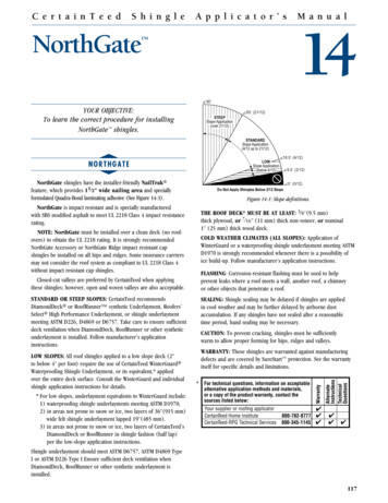
Figure 1. Nominal dimensions of DF4-LLHH and SJ4-LLHH lead connector (mm)1.2.3.4.36V TipRV RingRV CoilSVC Coil
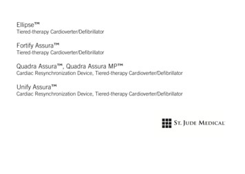
Figure 2. Nominal dimensions of IS4-LLLL and SJ4-LLLL lead connector, in mm1.2.3.4.Distal Tip 1Mid 2Mid 3Proximal 4SensingThe pulse generator has an Automatic Sensitivity Control feature to allow accurate sensing in both theatrium and the right ventricle over a wide range of signal strengths.NoteVentricular sensing is done only in the right ventricle.37
Table 10. Ranges for sensitivity settingsParameterRangeAtrial Maximum Sensitivity0.2–1.0 mVVentricular Defibrillator Maximum Sensitivity0.2–1.0 mVVentricular Pacemaker Maximum Sensitivity0.2–2.0 mVRadiopaque IdentificationEach pulse generator has an X-ray absorptive marker for non-invasive identification. The markerconsists of the St. Jude Medical logo (SJM) and a two-letter model code.Table 11. X-ray ID codes for the device models described in this manualDevice ModelX-ray ID Model Code38
Table 11. X-ray ID codes for the device models described in this manualDevice ModelX-ray ID Model CodeCD1257-40/40Q, CD1259-40/40Q, CD1261-40/40Q,CD1359-40/40C/40Q/40QC, CD2257-40/40Q, CD2259-40/40Q,CD2261-40/40Q, CD2359-40/40C/40Q/40QC, CD3257-40/40Q,CD3261-40/40Q, CD3265-40/40Q, CD3267-40/40Q,CD3271-40/40Q, CD3361-40/40C/40Q/40QC,CD3367-40/40C/40Q/40QC, CD3371-40/40C/40Q/40QCKCCD1275-36/36Q, CD1277-36/36Q, CD1279-36/36Q,CD1311-36/36Q, CD1377-36/36C/36Q/36Q
contact St. Jude Medical or consult your regulatory authorities to determine if the products have been certified as MR Conditional. Table 1. Single-chamber pulse generator descriptions . Name Model Number Description Connector Type Delivered Energy (approx.) MRI Status Fortify Assura VR CD1257-40 ;