Transcription
Syncro ASAnalogue AddressableFire Control PanelUser ManualMan-1100Issue 04 June 2013
IndexSectionPage1. Introduction.32. Safety .33. Panel Controls.43.1 Access Level 1 .43.2 Access Level 2 .54. Panel Operation .64.14.24.34.44.5Fire Event .6Fault Event .6Pre-alarm event .6Evacuate event .6Alert event .75. Access 2 Menu .75.15.25.35.45.55.6Disablements .7View Devices .8Test Zones .8Set System Time .8Contamination Status.9Access Level 3 .96. Panel printer – replacing printer paper .97. Routine Maintenance .9Product Manuals/Man-1100 Syncro AS User 04Page 2 of 9
1. IntroductionThe Syncro AS is an analogue addressable fire detection and alarm control panel that conforms to therequirements of European Standards EN54-2:1997 and EN54-4:1997.It is capable of covering a maximum of 16 zones (500 zones on a network) with 126 devices for Apolloprotocol, 127 devices per loop for Hochiki protocol and 240 devices per loop for Argus Vega protocol.Syncro AS also supports loop-powered sounders & beacons.Any number of devices can be allocated to any zone ensuring that any system configuration can be easilyaccommodated.Each detection device is allocated a message of up to 40 characters (including spaces) to assist in thelocation of the devices.The Syncro AS control panel offers an extensive list of features and options for the control and monitoringof plant, equipment and sounders.The range of compatible devices includes optical and ionisation smoke sensors, heat sensors, multi-sensors,switch monitors and relay or bell controllers. Interfaces to conventional detection systems can also becatered for using zone-monitoring devices.2. SafetySuppliers of articles for use at work are required under section 6 of the Health and Safety at Work act 1974to ensure as reasonably as is practical that the article will be safe and without risk to health when properlyused.An article is not regarded as properly used if it is used ‘without regard to any relevant information or advice’relating to its use made available by the supplier.This product should be installed, commissioned and maintained by trained service personnel in accordancewith the following:(i)IEE regulations for electrical equipment in buildings(ii)Codes of practice(iii)Statutory requirements(iv)Any instructions specifically advised by the manufacturerAccording to the provisions of the Act you are therefore requested to take such steps as are necessary toensure that you make any appropriate information about this product available to anyone concerned with itsuse.This equipment is designed to be operated from 230V 50Hz mains supplies and is of class 1 construction.As such it must be connected to a protective earthing conductor in the fixed wiring of the installation and areadily accessible double pole disconnect device shall be incorporated in the fixed wiring.Failure to ensure that all conductive accessible parts of this equipment are adequately bonded to theprotective earth will render the equipment unsafe.Product Manuals/Man-1100 Syncro AS User 04Page 3 of 9
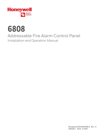
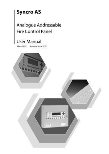
3. Panel Controls3.1 Access Level 1The front panel contains controls for operating the panel.Fig 1 – Syncro Front PanelLamp TestPress this button to illuminate all front panel indicators and validate correct operation.Silence BuzzerThis button will silence the internal buzzer, and will illuminate the Buzzer Silenced panel indicator. No othersounder outputs will be affected by this button operation.More FiresThis button is used to view suppressed fire events. In the case of multiple fire activations, or when fireactivation information has been temporarily suppressed for menu navigation, the fire events can be quicklyrestored and viewed by pressing this button.More EventsThis button is used to view all other suppressed events. In the case of multiple panel events or when anyevent information has been temporarily suppressed for menu navigation, this button is used to display theview events list.Menu Navigation (up / down / left / right / enter / exit)These are used to enter the password for access level 2 and are also used to navigate the Access 2 Facilities Menu.Help (?)This button offers additional information relating to the current status of the control panel. e.g. if the panelis in an alarm or fault condition then advice on the recommended action will be displayed or if a menufunction is being accessed then help relating to that function will be displayed.Product Manuals/Man-1100 Syncro AS User 04Page 4 of 9
3.2 Access Level 2Access level 2 can be reached by operating the Enable control keyswitch (where fitted) or by pressing any ofthe menu navigation (1, 2, 3 or 4) buttons. Pressing a menu button will then request the user to enter thecorrect Access level 2 password (a 4 digit number) followed by the Enter button.The factory default password for Access level 2 is 2222.The Access level 2 password can be changed at commissioning to meet customer’s requirements. Enter theAccess level 2 password in the space below for future reference.Access level 2 will be required by the end user to acknowledge alarms and reset the system.Any persons responsible for the fire alarm system should be aware of the Access level 2 password to enablethe panel controls.Without this password it will not be possible to acknowledge alarms or reset the system so it is mostimportant that the responsible person knows the password.ACCESS 2 PASSWORD .Silence Alarm / AcknowledgeThis button is normally used to mute any fire warning sounders fitted to the Syncro AS panel. Thesesounders are installed throughout the protected premises and are used to evacuate the premises.In some cases, the fire warning sounders may be delayed; to allow a search time before building evacuationcommences. In this case, the “Delay Active” panel indicator will be illuminated. If the Acknowledge Alarmbutton is pressed during the Delay Active period, the sounders may either be permanently muted or thedelay may be extended to the second stage delay time. This will depend upon the panel configuration andcannot be amended by the end user.If there is a second fire activation during an Active Delay, then all delays are cancelled and outputs willoperate in accordance with the building fire strategy.Re-sound AlarmIf any fire warning sounders have been muted using the Acknowledge Alarm button, then pressing the Resound Alarm will re-energise all muted sounders.ResetThis button is used to reset any activation that is defined as a latching input type. These will include fire andpre-alarm events. In general, fault events are non-latching and cannot be cleared by operation of the Resetbutton. These events will clear when the fault input is cleared.Function buttonThis button is a software programmable input that may be used to perform customer-defined actions. Thedefault operation of these buttons is to perform no action (transparent input).The operation of these buttons should be entered in the box below;Function button Evacuate buttonOperation on the Evacuate button will cause all sounders on the system that are configured to respond to anevacuate command (default) to sound continuously.Product Manuals/Man-1100 Syncro AS User 04Page 5 of 9
4. Panel Operation4.1 Fire EventIn the event of a fire, the red FIRE lamp and the appropriate Fire Zone indicator (if fitted) will flash. Detailsof the fire activation (address and location text) will be given in the LCD Status display.The fire warning sounders will sound throughout the building and the panel fire contact, alarm contact andfire routing outputs will be energised.The panel buzzer will be pulsing, but can be silenced by pressing the Silence Buzzer button.To silence the fire warning sounders, press any of the menu navigation buttons and enter the Access 2password (given in section 3.2) then press the Enter button.The panel controls will now be enabled and will remain enabled for about 1 minute after the last key hasbeen pressed.Pressing the Silence Alarm / Acknowledge button will now silence the sounders. The sounders can bestarted again if required by pressing the Re-Sound Alarm buttonThe system can be reset by pressing the Reset button.If there are more than two zones in fire on the system then these may be viewed in the text display bypressing the More Fires button.4.2 Fault EventIf there is a fault on the system, the yellow General Fault indicator will be flashing and there may be otherfault LED indications which identify the nature of the fault.The Fault Contact will be energised and the panel buzzer will be sounding continuously.Details of the fault will be described in the text display.The panel buzzer can be silenced at any time by pressing the Silence Buzzer button.If there are more than two fault events on the system then these may be viewed in the text display bypressing the More Events button.4.3 Pre-alarm eventSensors or inputs can generate a pre-alarm. A pre-alarm is used to warn of a slow change in the analoguelevel from detection devices, typically due to a smouldering fire. When a pre-alarm is generated, the controlpanel will illuminate the pre-alarm LED and will sound the internal buzzer continuously. The address andlocation of the source of the pre-alarm will be indicated in the LCD status display.The source of the pre-alarm input should be investigated.The panel buzzer can be silenced at any time by pressing the Silence Buzzer button.If there are more than two fault events on the system then these may be viewed in the text display bypressing the More Events button.4.4 Evacuate eventAn input on the system can be configured to create an Evacuate event. Operation of an evacuation input orthe Evacuate button will cause the red FIRE lamp to illuminate and all sounder devices to be operatedcontinuouslyThe panel buzzer will sound continuously and the source of the evacuation event will be shown in the LCDstatus display.The panel buzzer can be silenced at any time by pressing the Silence Buzzer button.To silence the fire warning sounders, press any of the menu navigation buttons and enter the Access 2password (given in section 3.2) then press the Enter button.The panel controls will now be enabled and will remain enabled for about 1 minute after the last key hasbeen pressed.Pressing the Acknowledge Alarm button will now silence the soundersIf the source of the event is a latching input, then pressing the Reset button will reset the system.Product Manuals/Man-1100 Syncro AS User 04Page 6 of 9
4.5 Alert eventAn input on the system can be configured to create an Alert event. Operation of an Alert input will cause allsounder devices to be pulsed on a 1 second cycle.The panel buzzer will sound continuously and the source of the alert event will be shown in the LCD statusdisplay.The panel buzzer can be silenced at any time by pressing the Silence Buzzer button.To silence the fire warning sounders, press any of the menu navigation buttons and enter the Access 2password (given in section 3.2) then press the Enter button.The panel controls will now be enabled and will remain enabled for about 1 minute after the last key hasbeen pressed.Pressing the Acknowledge Alarm button will now silence the soundersIf the source of the event is a latching input, then pressing the Reset button will reset the system.5. Access 2 MenuThere are a number of menu options available at access level 2. To view this menu, press the Right (2)pointing arrow key and enter the Access 2 password (given in section 3.2) then press the Enter button oroperate the Enable controls keyswitch if fitted.The panel controls will now be enabled and will remain enabled for about 120 seconds after the last key hasbeen pressed.When in Access 2, press any of the four navigation buttons to view the Access 2 menu.To navigate the menu, use the Up (1) and Down (3) buttons to move the cursor to the required menuoption. Use the Right (2) button to select the highlighted menu option. Use the Left (4) button to exitback to the main menu. Use the Enter button to input the required information and the Exit button tocancel any data selection. Pressing the Help (?) button will display the help screen appropriate to thecurrent menu selection.ACCESS LEVEL 2DisablementsView devicesTest ZonesSet system timeContamination StatusAccess level 3Main menu items available at access levels 2:5.1 DisablementsAny disablements made using this menu will remain active until the disablement is cleared by manualintervention at the panel.Disable Immediate Output ResponseIf any outputs are configured to be delayed (an Access Level 3 configuration operation), then EN54 requiresthat these outputs are not delayed, unless set to do so at Access Level 2. This menu option allows delays tooutputs to be activated, by disabling the immediate response facility.Disable ZonesAll detection devices, including manual call points, are disabled in the selected zone.Disable AddressesAny loop device can be disabled using this menu option. In devices with more than one input or output, theneach sub-address may be individually disabled.Product Manuals/Man-1100 Syncro AS User 04Page 7 of 9
Disable SoundersThis menu option is used to disable all sounder outputs fitted to the control panel. A sounder output isdefined as any output that has been set to respond to the Silence and Evacuate panel commands. Sounderoutputs may be directly wired to the control panel (Sounder circuits 1 and 2) or loop driven devices.The Sounder Fault / Disabled LED indicator will be illuminated, as well as the General Disablement Indicator.Disable Panel OutputsThis menu option allows the following panel outputs to be independently disabled; Fire ContactAlarm ContactFault ContactWhen the Fire Routing output is disabled, the front panel Fire Routing Fault / Disabled indicator and GeneralDisablement indicator will be permanently illuminated.View / Restore DisablementsTo cancel any disablements, there are two options. The first is to scroll through each individual menu option,then toggle any disablements to the normal condition. The second, preferred option, is to use the View /Restore Disablements option. This menu option will allow the user to scroll through all active disablementsand individually enable each disablement by pressing the Enter button.5.2 View DevicesThis menu option permits the user to view all addresses connected to the detection circuit. For each address& sub-address, the LCD status display will give the device type, zone and location text. In addition,analogue devices will give an indication of the analogue value of the current device.For digital input devices (Manual call points, switch monitor units etc) the input state is given, either asNormal or Activated. For output devices, the output state will be shown as either Normal, Intermittent ofContinuous.This menu is used by experienced personnel to investigate the current status of the system and may help infault finding techniques.5.3 Test ZonesTest ZonesEach zone may be individually put in to a Test Mode condition. When test mode is selected, the devices inthe zone may be tested and the Syncro AS panel will automatically reset after 3 seconds. This is used forone man testing of the fire system.When a zone is put in to test mode, the user is prompted to select the sounder response behaviour for theselected zone. When set to the ON position, all sounder outputs will sound for the duration of the fire event.The sounders will be muted when the panel automatically resets.NOTE: On systems with a high number of Loop powered sounders fitted, all sounders may not be able toactivate within the 3 second fire period and therefore loop sounder confirmation may be intermittent.View & Restore Zones in TestTo cancel any zones in test, there are two options. The first is to scroll through each zone in the Test Zonemenu, then toggle any active zones to the normal condition. The second is to use the View / Restore Zonesin Test option. This menu option will allow the user to scroll through all active zones in test and individuallyenable each disablement by pressing the Enter button.5.4 Set System TimeThis menu option is used to set the panel date and time. This is necessary so that any events are accuratelylogged in the event log and on the panel printer (if fitted). The panel automatically compensate s fordaylight saving time.Product Manuals/Man-1100 Syncro AS User 04Page 8 of 9
5.5 Contamination StatusAny detection devices that exceed 85% of the limit for the manufacturers working range during the dailycalibration sequence are added to a contaminated device menu. At this stage, the panel will not notify theuser of a fault for the contaminated devices.This menu option allows the user to see any devices approaching their maintenance fault limits and toprevent unnecessary faults being reported from dirty detection devices.This menu is typically used as a preventative maintenance feature.5.6 Access Level 3This menu option is used to enter the access 3 password for the engineering function menu.Details of the options available at Access level 3 can be found in the Syncro AS Product manual.6. Panel printer – replacing printer paperThe Syncro AS panel is available with or without an internal printer.The printer is of the thermal type and requires heat sensitive paper rolls. When the paper rolls are nearlyfinished, a red line will be seen on one (or both) sides of the printer paper. As soon as this red line is visible,the fire system service company should be informed and a trained service engineer should replace theprinter paper.To gain access to the panel printer, it is necessary to open the Syncro AS door and expose the internalcomponents of the control panel, including the mains supply terminations. This makes it unsuitable for theend user to change the printer paper on this product.7. Routine MaintenanceSyncro AS control panels do not require any specific maintenance but should the control panel become dirtyit can be wiped over with a barely damp cloth. Detergents or solvents should not be used to clean the paneland care must be taken that water does not enter the enclosure.The control panel contains sealed lead acid batteries to provide standby power in the event of mains failure.These batteries have a life expectancy of around 4 years. It is recommended that these batteries be annuallytested in accordance with the battery manufacturer’s recommendations to determine their suitability forcontinued standby applications.Routine testing of the fire alarm system in accordance with BS5839: Part 1: 2002 will identify anymalfunction of the control panel and any malfunction should be reported to the fire alarm maintenancecompany immediately.Detection devices are automatically calibrated on a daily basis and any devices that fail the detectormanufacturer requirements will be notified as a maintenance fault. The contamination status menu is alsouseful in determining detection devices that are approaching their working range limits (see 5.5 above).Product Manuals/Man-1100 Syncro AS User 04Page 9 of 9
Product Manuals/Man-1100 Syncro AS User_04 Page 3 of 9 1. Introduction The Syncro AS is an analogue addressable fire detection and alarm control panel that conforms to the requirements of European Standards EN54-2:1997 and EN54-4:1997. It is capable of covering a maximum of 16 zones (500 zones on a network) with 126 devices for Apollo