Transcription
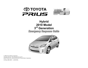
Hybrid2010 Model3rd Generation 2009 Toyota Motor CorporationAll rights reserved. This document may not bealtered without the written permission of Toyota Motor Corporation.10 Prius ERG REV – (03/05/09)
ForewordIn May 2000 and October 2003, Toyota introduced the 1st and 2ndgeneration Toyota Prius gasoline-electric hybrid vehicles in NorthAmerica. To educate and assist emergency responders in the safehandling of Toyota Prius technology, Toyota published the 2000 and2004 Toyota Prius Emergency Response Guides. A body electrical system rated at 12 Volts, negative chassis ground.Supplemental Restraint System (SRS) – dual stage frontal airbags,front seat mounted side airbags, side curtain airbags, front seatbeltpretensioners, and driver knee airbag.High voltage electrical safety remains an important factor in theemergency handling of the Prius Hybrid Synergy Drive. It is importantto recognize and understand the disabling procedures and warningsthroughout the guide.rdWith the release of the 3 generation Toyota Prius in March 2009, anew 2010 Toyota Prius Emergency Response Guide was published foremergency responders. While many features from the 1st and 2ndgeneration Prius models are similar, emergency responders shouldrecognize and understand the new, updated features of the Priuscovered in this guide.Additional topics in the guide include: Prius identification. Major Hybrid Synergy Drive component locations and descriptions. Extrication, fire, recovery, and additional emergency responseinformation. Roadside assistance information.High voltage electricity powers the electric motor, generator, airconditioning compressor and inverter/converter. All other automotiveelectrical devices such as the headlights, radio, and gauges are poweredfrom a separate 12 Volt auxiliary battery. Numerous safeguards havebeen designed into the Prius to help ensure the high voltage,approximately 201.6 Volt, Nickel Metal Hydride (NiMH) HybridVehicle (HV) battery pack is kept safe and secure in an accident.The Prius utilizes the following electrical systems: Maximum 650 Volts AC Nominal 201.6 Volts DC Nominal 12 Volts DC2010 Model YearPrius3rd generation Prius Features: Complete model change with a new exterior and interior design. A boost converter in the inverter/converter that boosts the availablevoltage to the electric motor to 650 Volts. A high voltage Hybrid Vehicle (HV) battery pack rated at 201.6Volts. A high voltage motor driven Air Conditioning (A/C) compressorrated at 201.6 Volts. An optional solar ventilation system and remote air conditioningsystem.2004 – 2009 Model YearPriusThis guide is intended to assist emergency responders in the safehandling of a Prius vehicle during an incident.-i-
Table of ContentsPageAbout the Prius1Prius Identification2Hybrid Synergy Drive Component Locations & Descriptions5Smart Key System8Electronic Gearshift Selector10Hybrid Synergy Drive Operation11Hybrid Vehicle (HV) Battery Pack12Solar Ventilation and Remote Air Conditioning Systems13Low Voltage Battery15High Voltage Safety16SRS Airbags & Seat Belt Pretensioners17Emergency ing of NiMH HV Battery PackSpillsFirst AidSubmersionRoadside Assistance1926272728282930-ii-
About the PriusThe Prius continues into its 3rd generation as a gasoline-electric hybridvehicle. Hybrid Synergy Drive means that the vehicle contains agasoline engine and electric motor for power. The two hybrid powersources are stored on board the vehicle:1. Gasoline stored in the fuel tank for the gasoline engine.2. Electricity stored in a high voltage Hybrid Vehicle (HV) battery packfor the electric motor.The result of combining these two power sources is improved fueleconomy and reduced emissions. The gasoline engine also powers anelectric generator to recharge the battery pack; unlike a pure all electricvehicle, the Prius never needs to be recharged from an external electricpower source.Depending on the driving conditions one or both sources are used topower the vehicle. The following illustration demonstrates how thePrius operates in various driving modes.During full acceleration, such as climbing a hill, both the gasolineengine and the electric motor power the vehicle.During light acceleration at low speeds, the vehicle is powered bythe electric motor. The gasoline engine is shut off.During deceleration, such as when braking, the vehicle regeneratesthe kinetic energy from the front wheels to produce electricity thatrecharges the battery pack.During normal driving, the vehicle is powered mainly by thegasoline engine. The gasoline engine also powers the generator torecharge the battery pack.While the vehicle is stopped, the gasoline engine and electric motorare off, however the vehicle remains on and operational.-1 -
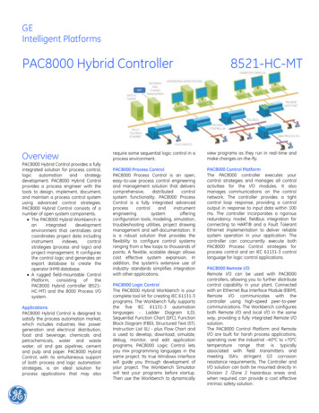
Prius IdentificationExteriorIn appearance, the 2010 model year Prius is a 5-door hatchback.Exterior, interior, and engine compartment illustrations are provided toassist in identification.andlogos on the back door.Gasoline fuel filler door located on driver side rear quarter panel.The alphanumeric 17 character Vehicle Identification Number (VIN) isprovided in the front windshield cowl and on the driver door pillar.Example VIN: JTDKN36UA82020211A Prius is identified by the first 8 alphanumeric charactersJTDKN36U.Exterior Left Side ViewDriver Side Windshield and Left Side B PillarExterior Front and Rear ViewExterior Rear and Left Side View-2 -
Prius Identification (Continued)InteriorInstrument cluster (speedometer, READY light, shift position indicators,warning lights) located in center of the dash and near the base of thewindshield.Interior ViewInstrument Cluster View-3 -
Prius Identification (Continued)Engine Compartment1.8-liter aluminum alloy gasoline engine.Logo on the plastic engine cover.Engine Compartment View-4 -
Hybrid Synergy Drive Component Locations &DescriptionsComponentLocation12 VoltAuxiliaryBatteryHybridVehicle (HV)Battery PackRight Side ofCargo AreaA lead-acid battery that supplies power tothe low voltage devices.Cargo Area,Mounted to CrossMember behindRear SeatUndercarriageand EngineCompartment201.6 Volt Nickel Metal Hydride (NiMH)battery pack consisting of 28 low voltage(7.2 Volt) modules connected in scriptionOrange colored power cables carry highvoltage Direct Current (DC) between theHV battery pack, inverter/converter, andA/C compressor. These cables also carry 3phase Alternating Current (AC) between theinverter/converter, electric motor, andgenerator.Boosts and inverts the high voltageelectricity from the HV battery pack to 3phase AC electricity that drives the electricmotor. The inverter/converter also convertsAC electricity from the electric generatorand electric motor (regenerative braking) toDC that recharges the HV battery pack.Provides two functions:1) Powers vehicle.2) Powers generator to recharge the HVbattery pack.The engine is started and stopped undercontrol of the vehicle computer.3-phase high voltage AC permanent magnetelectric motor contained in the fronttransaxle. It is used to power the frontwheels.3-phase high voltage AC generator that iscontained in the transaxle and recharges theHV battery pack.Hybrid Synergy Drive ComponentsComponents (Top View) and High Voltage Power Cables-5 -
Hybrid Synergy Drive Component Locations &Descriptions l Tankand Fuel LineLocationDescriptionEngineCompartment3-phase high voltage AC electrically drivenmotor compressor.Undercarriageand CenterThe fuel tank provides gasoline via a fuelline to the engine. The fuel line is routedunder the center of vehicle.Fuel Tank and Fuel Line-6 -
Hybrid Synergy Drive Component Locations &Descriptions (Continued)Key Specifications:Aluminum HoodGasoline Engine: 98 hp (73 kW), 1.8-liter Aluminum Alloy EngineElectric Motor: 80 hp (60 kW), Permanent Magnet MotorTransmission: Automatic Only (electrically controlledcontinuously variable transaxle)HV Battery: 201.6 Volt Sealed NiMH BatteryAluminum Back DoorCurb Weight: 3,080 lbs/1,397 kgFuel Tank: 11.9 gals/45.0 litersFrame Material: Steel UnibodyBody Material: Steel Panels except for Aluminum Hood and BackDoorSteel Unibody-7 -
Smart Key SystemThe Prius smart key system consists of a smart key transceiver thatcommunicates bi-directionally, enabling the vehicle to recognize thesmart key in proximity to the vehicle. Once recognized, the smart keywill allow the user to lock and unlock the doors without pushing smartkey buttons, and start the vehicle without inserting it into an ignitionswitch.Release ButtonSmart key features: Passive (remote) function to lock/unlock the doors and start thevehicle. Wireless transmitter buttons to lock/unlock all 5 doors. Hidden metal cut key to lock/unlock the doors.Smart Key (Fob)Hidden Metal Cut Key for Door LockUnlock Touch SensorDoor (Lock/Unlock)There are several methods available to lock/unlock the doors. Pushing the smart key lock button will lock all doors including the backdoor. Pushing the smart key unlock button once unlocks the driver door,twice unlocks all doors.Touching the sensor on the backside of the driver door exterior handle, withthe smart key in proximity to the vehicle, unlocks the driver door. Touchingthe sensor on the backside of the front passenger door exterior handle, withthe smart key in proximity to the vehicle, unlocks all doors. Touching thelock sensor on either front door, or the lock button for the back door willlock all doors.Inserting the hidden metal cut key in the driver door lock and turningclockwise once unlocks the driver door, twice unlocks all doors. To lockall doors turn the key counter clockwise once. Only the driver doorcontains an exterior door lock for the metal cut key.Lock Touch SensorsDriver Door Unlock Touch Sensor andLock Touch SensorOptional Back Door Lock Button-8 -Use the Hidden Metal Cut KeyFront Driver Door Lock
Smart Key System (Continued)Ignition ModeOffAccessoryIgnition-OnBrake Pedal DepressedVehicle Started (READY-ON)MalfunctionVehicle Starting/StoppingThe smart key has replaced the conventional metal cut key, and the powerbutton with an integral status indicator light has replaced the ignition switch.The smart key only needs to be in proximity to the vehicle to allow the systemto function. Power Button Indicator LightOffAmberAmberGreenOffBlinking AmberWith the brake pedal released, the first push of the power button operatesthe accessory mode, the second push operates the ignition-on mode, and thethird push turns the ignition off again.Ignition Mode Sequence (brake pedal released):Vehicle Off Button Push Accessory Button Push Ignition-OnButton Push Starting the vehicle takes priority over all other ignition modes and isaccomplished by depressing the brake pedal and pushing the power buttononce. To verify the vehicle has started, check that the power button statusindicator light is off and the READY light is illuminated in the instrumentcluster. If the internal smart key battery is dead, use the following method to startthe vehicle.1. Touch the Toyota emblem side of the smart key to the power button.2. Within the 5 seconds after the buzzer sounds, push the power buttonwith the brake pedal depressed (the READY light will illuminate). Once the vehicle has started and is on and operational (READY-ON), thevehicle is shut off by bringing the vehicle to a complete stop and thendepressing the power button once. To shut off the vehicle before coming to a stop in an emergency, push andhold down the power button for more than 3 seconds. This procedure maybe useful at an accident scene in which the READY indicator is on, Parkcannot be selected, and the drive wheels remain in motion.-9 -Power Button with Integral StatusIndicator LightIgnition Modes (Brake Pedal Released)Starting Sequence(Brake Pedal Depressed)Smart Key Recognition(When Smart Key Battery is Dead)
Electronic Gearshift SelectorThe Prius electronic gearshift selector is a momentary select shift-bywire system that engages the transaxle in Reverse, Neutral, Drive, orengine Brake modes. These modes may only be engaged while the vehicle is on and operational(READY-on), except for Neutral which may also be engaged while in theignition-on mode. After selecting the gear position R, N, D, or B thetransaxle remains in that position, identified on the instrument cluster, butthe shift selector returns to a default position. To select Neutral, it isnecessary to hold the shift selector in the N position for approximately 0.5seconds.DefaultPositionUnlike a conventional vehicle, the electronic shift selector does not containa park position. Instead, a separate P switch located above the shift selectorengages the park. When the vehicle is stopped, regardless of shift selector position, theelectro-mechanical parking pawl is engaged to lock the transaxle into parkby either depressing the P switch or pushing the power button to shut offthe vehicle. Being electronic, the gearshift selector and the park systems depend on thelow voltage 12-Volt auxiliary battery for power. If the 12-Volt auxiliarybattery is discharged or disconnected, the vehicle cannot be started andcannot be shifted out of park.Electronic Gearshift Selector and P SwitchIndicatesGear PositionInstrument Cluster Gear Position Indicator-10-
Hybrid Synergy Drive OperationOnce the READY indicator is illuminated in the instrument cluster, thevehicle may be driven. However, the gasoline engine does not idle like atypical automobile and will start and stop automatically. It is importantto recognize and understand the READY indicator provided in theinstrument cluster. When lit, it informs the driver that the vehicle is onand operational even though the gasoline engine may be off and theengine compartment is silent.Vehicle Operation With the Prius, the gasoline engine may stop and start at any time while theREADY indicator is on. Never assume that the vehicle is shut off just because the engine is off.Always look for the READY indicator status. Although the vehicle is shutoff when the READY indicator is off, the optional remote air conditioningsystem can still operate using high voltage power from the HV battery pack(see remote air conditioning system description on page 14). The vehicle may be powered by:1. The electric motor only.2. The gasoline engine only.3. A combination of both the electric motor and the gasoline engine. The vehicle computer determines the mode in which the vehicle operates inorder to improve fuel economy and reduce emissions. Three new featureson the 2010 Prius are EV (Electric Vehicle) mode, Power mode and ECO(Economy) mode:Instrument Cluster READY Indicator1. EV Mode: When activated, and certain conditions have been met,2.3.the vehicle operates with the electric motor powered by the HVbattery.ECO Mode: When activated, this mode helps enhance fueleconomy on trips that involve frequent braking and acceleration.Power Mode: Optimizes acceleration feel by increasing the poweroutput more quickly at the beginning of accelerator pedaloperation.EV Drive Mode Switch/Economy Drive Mode Switch/Power Mode Switch-11-
Hybrid Vehicle (HV) Battery PackComponents Powered by the HV Battery PackThe Prius features a high voltage Hybrid Vehicle (HV) battery pack thatcontains sealed Nickel Metal Hydride (NiMH) battery modules. HV Battery Pack The HV battery pack is enclosed in a metal case and is rigidly mounted tothe cargo area floor pan cross member behind the rear seat. The metal caseis isolated from high voltage and concealed by carpet in the cabin area. The HV battery pack consists of 28 low voltage (7.2 Volt) NiMH batterymodules connected in series to produce approximately 201.6 Volts. EachNiMH battery module is non-spillable and in a sealed case. The electrolyte used in the NiMH battery module is an alkaline mixture ofpotassium and sodium hydroxide. The electrolyte is absorbed into thebattery cell plates and will not normally leak, even in a collision.Front Electric MotorPower CablesElectric Generator Inverter/ConverterA/C CompressorHV Battery Pack RecyclingThe HV battery pack is recyclable. Contact the nearest Toyota dealer.HV Battery PackBattery pack voltageNumber of NiMH battery modules in the packNiMH battery module voltageNiMH battery module dimensionsNiMH module weightNiMH battery pack dimensionsNiMH battery pack weight201.6 V287.2 V11.2 x 0.8 x 4.6 in(285 x 19.6 x 117.8 mm)2.3 lbs (1.04 kg)11.7 x 23.2 x 0.42 in(297 x 590 x 10.7 mm)90 lbs (41 kg)HV Battery Pack-12-
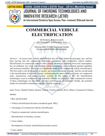
Solar Ventilation and Remote Air Conditioning SystemsTwo newly available options on the 2010 Prius are the solar ventilationsystem and the remote air conditioning system. These systems areprovided for occupant comfort by lowering the inside cabin temperaturewhile the vehicle is shut off and parked.Solar PanelSolar Ventilation SystemWiringThe solar ventilation system uses energy provided by a solar panel built into theroof to operate a fan contained within the air conditioning system. This allowsventilation of the vehicle interior when the vehicle is parked in direct sunlight.The solar panel consists of 36 poly crystalline silicon cells connected in series.The panel produces a nominal 22 Volts DC and 3.6 Amps (cell temperature77oF (25oC), sunlight intensity of 1000 W/m2). The maximum output of thesolar panel is 27 Volts at -22oF (-30oC) and maximum 3.6 Amps in full sunlightintensity. The power output is not connected to the 12 Volt auxiliary batteryand will not backfeed the 12 Volt auxiliary battery circuit or SRS circuits.GlassPotting Material(Ethylene Vinyl Acetate Resin)Back Sheet (Polyvinyl Fluoride Resin)The solar panel is primarily constructed from glass, potting material, silicon,silver and aluminum compounds, and a back sheet. Aside from the risk ofinjury due to broken glass, breaking or cutting into the optional solar panel isotherwise not a hazard. Due to the difficulty of breaking or cutting the solarpanel, these operations are not recommended.Solar Cell (Silicon, Silver andAluminum Compounds)Optional Roof Solar PanelNOTE:If it is necessary to cut the solar panel, in order to stop the modules fromgenerating electricity, at least one solar module must first be covered with amaterial such as thick fabric that blocks sunlight.Cover the Solar Module-13-
Solar Ventilation and Remote Air Conditioning Systems(Continued)Remote Air Conditioning SystemThe remote air conditioning system uses energy stored in the High Voltage HVbattery pack to operate the high voltage air conditioning compressor. Thisallows preconditioning of the vehicle interior when the vehicle is shut off andparked. The system is activated remotely by pushing the smart key A/C buttonand will operate for up to three minutes when certain conditions are met.The air conditioning system will automatically shut off After about 3 minutes has elapsed since operation started. When HV battery pack charge level is low. When a door is opened. When the smart key A/C button is pushed twice within 3 seconds. When any of the operating conditions are not met.Optional Remote Air Conditioning SystemAs a security feature, unlocked doors are automatically locked when the systemis activated.NOTE:When the optional remote air conditioning system is activated, high voltagepower is supplied from the HV battery pack to the air conditioning system, butthe vehicle’s gasoline engine and electric motor are shut off (the instrumentcluster lights are on, but the READY indicator is off).-14-
Low Voltage BatteryAuxiliary Battery The Prius contains a sealed lead-acid 12 Volt battery. The 12 Voltauxiliary battery powers the vehicle’s electrical system similar to aconventional vehicle. As with conventional vehicles, the negative terminalof the auxiliary battery is grounded to the metal chassis of the vehicle. The auxiliary battery is located in the cargo area. It is concealed by a fabriccover on the right side in the rear quarter panel well.NOTE:An under hood label shows the location of the HV battery (traction battery)and 12 Volt auxiliary battery.Remove center deck boardRemove center auxiliary boxBattery Cover12 Volt Auxiliary Battery Mounted inCargo AreaBattery Location Label-15-
High Voltage Safety The HV battery pack powers the high voltage electrical system with DCelectricity. Positive and negative orange colored high voltage power cables arerouted from the battery pack, under the vehicle floor pan, to theinverter/converter. The inverter/converter contains a circuit that boosts the HVbattery voltage from 201.6 to 650 Volts DC. The inverter/converter creates 3phase AC to power the motor. Power cables are routed from theinverter/converter to each high voltage motor (electric motor, electric generator,and A/C compressor). The following systems are intended to help keepoccupants in the vehicle and emergency responders safe from high voltageelectricity:A ground fault monitor continuously monitors for high voltage leakageto the metal chassis while the vehicle is running. If a malfunction isdetected, the hybrid vehicle computer will illuminate the master warninglightin the instrument cluster and indicate “Check Hybrid System” onthe multi-information display.High Voltage Safety System A high voltage fusepack. Positive and negative high voltage power cables connected to the HVbattery pack are controlled by 12 Volt normally open relays . When thevehicle is shut off, the relays stop electrical flow from leaving the HVbattery pack.provides short circuit protection in the HV batteryHigh Voltage Safety System – Vehicle Shut Off (READY-OFF)NOTE:When activated, the optional remote air conditioning system on the 2010 Priuswill activate the relays allowing high voltage to flow to the air conditioningcompressor while the vehicle is shut off and the READY indicator is off. Formore information on the remote air conditioning system, see the details on Page14.WARNING:The high voltage system may remain powered for up to 10 minutes afterthe vehicle is shut off or disabled. To prevent serious injury or deathfrom severe burns or electric shock, avoid touching, cutting, orbreaching any orange high voltage power cable or high voltagecomponent.High Voltage Safety System – Vehicle On and Operational (READY-ON) Both positive and negative power cables are insulated from the metalchassis, so there is no possibility of electric shock when touching the metalchassis.-16-
SRS Airbags & Seat Belt PretensionersStandard Equipment Electronic frontal impact sensors (2) are mounted in the enginecompartment as illustrated.Front seat belt pretensioners are mounted near the base of the B-pillars .A frontal driver airbag is mounted in the steering wheel hub.A frontal twin-chamber shaped dual stage passenger airbag is integratedinto the dashboard and deploys through the top of the dashboard.The SRS computer , which contains an impact sensor, is mounted on thefloor pan underneath the instrument panel, forward of the shift lever.Front electronic side impact sensors (2) are mounted near the base of the Bpillars.Rear electronic side impact sensors (2) are mounted near the base of the Cpillars.Front seat side airbags are mounted in the front seatbacks.Side curtain airbags are mounted along the outer edge inside the roofrails.Driver knee airbags are mounted on the lower portion of the dash.Active (mechanical non-pyrotechnic) front seat headrests (see descriptionon page 25).Electronic Impact Sensors and Side AirbagsSide Curtain AirbagInflatorsOptional Equipment The optional pre-collision safety system contains a radar sensorysystem and an electric motor-pyrotechnic pretensioner system. During apre-collision event, an electric motor in the pretensioners retracts thefront seatbelt. When conditions stabilize the electric motor will reverseitself. When the airbags deploy, the pyrotechnic pretensioners functionnormally.WARNING:The SRS may remain powered for up to 90 seconds after the vehicle isshut off or disabled. To prevent serious injury or death fromunintentional SRS deployment, avoid breaching the SRS components.Standard Frontal Airbags, Seat Belt Pretensioners, Knee Airbag, Side CurtainAirbags-17-
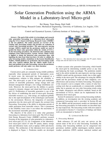
SRS Airbags & Seat Belt Pretensioners (Continued)NOTE:The front seatback mounted side airbags and the side curtain airbags maydeploy independently of each other.The knee airbag deploys simultaneously with the frontal airbags.The Prius is equipped with a standard front passenger occupantclassification system that may prohibit the deployment of the frontpassenger frontal airbag, knee airbag, seatback mounted side airbag, andseat belt pretensioners. If the passenger occupant classification systemprohibits deployment during an SRS event, the passenger SRS will not rearm nor deploy.Side Airbag SensorFront Seat Side AirbagFront Seat BeltPretensionerSide Curtain AirbagRear SideAirbag SensorPassenger Frontal AirbagFrontal, Knee, Front and Rear Seatback Mounted Side, Side Curtain Airbags.Front AirbagSensorsKnee AirbagRear SideAirbag SensorDriver Frontal AirbagFront Seat Side AirbagFront Seat BeltPretensionerSide Curtain AirbagSide Airbag SensorSRS System DiagramDriver Knee Airbag and Inflator-18-
Emergency ResponseOn arrival, emergency responders should follow their standardoperating procedures for vehicle incidents. Emergencies involving thePrius may be handled like other automobiles except as noted in theseguidelines for Extrication, Fire, Overhaul, Recovery, Spills, First Aid,and Submersion.WARNING: Never assume the Prius is shut off simply because it is silent.Always observe the instrument cluster for the READY indicatorstatus to verify whether the vehicle is on or shut off. The vehicleand optional remote air conditioning system are shut off when theREADY indicator is off and the instrument cluster lights are out.Failure to shut off and disable the vehicle before emergencyresponse procedures are performed may result in serious injury ordeath from the unintentional deployment of the SRS or severe burnsand electric shock from the high voltage electrical system.Chock WheelsExtrication Immobilize VehicleChock wheels and set the parking brake.Push the P switch to engage park. Disable VehiclePerforming either of the following two procedures will shut thevehicle off and disable the HV battery pack, SRS, optional remote airconditioning system, and gasoline fuel pump.P Switch-19-Set Parking Brake
Emergency Response (Continued)Extrication (Continued)Procedure #11.Confirm the status of the READY indicator in the instrumentcluster. If the READY indicator is illuminated, the vehicle is onand operational.NOTE:For vehicles with the optional remote air conditioning system,although the READY indicator is off, high voltage may be suppliedto the air conditioning system if the instrument cluster lights are on.Be sure to perform the remaining steps of this procedure.2.3.4.5.Shut off the vehicle by pushing the power button once.The vehicle is already shut off if the instrument cluster lights arenot illuminated. Do not push the power button because thevehicle may start.If the smart key is easily accessible, keep it at least 16 feet (5meters) away from the vehicle. Do not push the A/C button onthe key, because this may energize the high voltage circuit usedfor the optional remote air conditioning system.Disconnect the 12 Volt auxiliary battery under the cover in thecargo area to prevent accidental restarting of the vehicle andoptional remote air conditioning system.Shut Off Vehicle (READY-OFF)-20-Remove center deck boardRemove center auxiliary boxRemove Auxiliary Battery Cover12 Volt Auxiliary Battery in CargoArea
Emergency Response (Continued)Extrication (Continued)Procedure #2 (Alternate if power button is inaccessible)1.2.3.4.Open the hood.Remove the fuse box cover.Remove the IGCT fuse (30A green colored) and AM2 fuse(7.5A orange colored) in the engine compartment fuse box (referto illustration). If the correct fuse cannot be recognized, pull allfuses in the fuse box.Disconnect the 12 Volt auxiliary battery under the cover in thecargo area.Remote Hood ReleaseNOTE:Before disconnecting the 12 Volt auxiliary battery, if necessary,lower the windows, unlock the doors and open the back door asrequired. Once the 12 Volt auxiliary battery is disconnected, powercontrols will not operate.Hood Latch ReleaseAM2 fuse (7.5A Orange)WARNING: The high voltage system may remain powered for up to 10 minutes after the vehicle is shut off or disabled. To prevent serious injuryor death from severe burns or electric shock, avoid touching,cutting, or breaching any orange high voltage power cable or highvoltage component.The SRS may remain powered for up to 90 seconds after the vehicleis shut off or disabled. To prevent serious injury or death fromunintentional SRS deployment, avoid breaching the SRScomponents.If none of the disabling procedures can be performed, proceed withcaution as there is no assurance that the high voltage electricalsystem, SRS, optional remote air conditioning system, or fuel pumpare disabled.The high voltage motor compressor for the optional remote airconditioning system can be operated when the hybrid system is offby pressing a button on the key. When disabling the vehicle orunlocking the doors, do not press the A/C button on the key. Makesure to disconnect the 12 Volt auxiliary battery to preventinadvertent operation of the optional remote air conditioning.IGCT fuse (30A Green)-21-Remove Fuse Box CoverIGCT and AM2 Fuse Location inEngine Compartment Fuse BoxRemove Battery Cover12 Volt Auxiliary Battery in CargoArea
Emergency Response (Continued)Extrication (Continued) Stabilize VehicleCrib at (4) points directly under the front and rear pillars.Do not place cribbing under the high voltage power cables, exhaustsystem, or f
With the release of the 3rd generation Toyota Prius in March 2009, a new 2010 Toyota Prius Emergency Response Guide was published for emergency responders. While many features from the 1st and 2nd generation Prius models are similar, emergency responders should recognize and understand the new, updated features of the Prius covered in this guide.