Transcription
CASE LETTERTrephine Core: An Alternative Sinus Lift TechniqueLanka Mahesh, BDS, MS1Gregori M. Kurtzman, DDS, MAGD, DICOI2*Sagrika Shukla, BDS3INTRODUCTIONTypically, the posterior maxilla demonstrates the lowest density of bone in theoral cavity. The posterior edentulousmaxilla also presents special challengesin implant placement compared withother areas of the mouth due to progressiveresorption that results in less available bone. Thispoor quality and quantity of available bonechallenges the essential condition for successfulimplant placement.The maxillary sinus is an air cavity located in themaxilla that enlarges after tooth loss, complicatingimplant placement in this region. It is pyramidal inshape and is frequently reinforced with internalvertical septa, creating further intrasinus cavities.1After tooth extraction, the initial decrease in bone isdue to resorption of buccal bone plate that is oflower density and thinner in cross section than thepalatal osseous plate. As the edentulous areacontinues to atrophy, there is a continuing loss ofbone height and density and an increase in antralpneumatization.2,3 As a result, the sinus floorenlarges in a crestal direction, decreasing availableosseous height for implant placement over time.This finding is related to 2 phenomena: (1) theenlargement of the sinus at the expense of thealveolus after tooth extraction because of theincreased osteoclastic activity of the periosteum ofthe schneiderian membrane4 and (2) increasedpneumatization of the sinus simply because of theincrease in positive intra-antral pressure.5 In addition, the maxilla is made of primarily spongy boneand is composed of the least dense bone in the oralenvironment. The amount of bone inferior to thesinus is often limited. Thus, treatment of theposterior maxilla depends on the amount of bone1Private practice, New Delhi, India.Private practice, Silver Spring, MD.Private practice, New Delhi, India.* Corresponding author, e-mail: drimplants@aol.comDOI: 10.1563/AAID-JOI-D-14-0004723present in the subsinus region. The longer the site isedentulous or the higher the amount of periodontalinflammation present before tooth extraction influence how much available bone height and widthwill be present for implant placement. To achieveideal height and width of posterior maxilla, sinus liftprocedures are often required.1Tatum4 was the first to report penetration of themaxillary sinus with a modified Caldwell-Luc technique. This technique makes use of an unfinishedfenestration osteotomy in the maxilla’s external faceto raise the sinus membrane, creating a hole in thefloor of the antral cavity. This hole is then filled witha grafting material, providing required dimensionsof the bone for implant placement. However, one ofthe most common complications of this techniqueis perforation of the Schneiderian membrane.Today, to overcome this complication many modifications are available, depending upon the available bone. Sinus lift procedure using trephine is onesuch procedure that was introduced by Emtiaz etal.6In this technique, after raising a mucoperiostealflap, by use of a trephine on a straight implanthandpiece, a round bone cut is made 4–5 mmabove the crest of the alveolar ridge and inferior tothe sinus floor by several millimeters. A trephinedrill is a hollow cylinder with a serrated terminaledge that creates a cylinder of bone in the osseoussite (Figure 1). The outer bony cortex is removedgently to avoid tearing the membrane; this isimportant because the membrane can later beused for repositioning over the graft or crushed andused as particulate graft material in the site. Theexposed membrane is then lifted from the sinusfloor using osteotomes (Figure 2). Additional graftmaterial is placed until the lateral wall of the maxillais reconstituted. The mucoperiosteal flap is repositioned and sutured.1When the trephine technique is to be used withsimultaneous implant placement, a trephine isselected that has an outer diameter no greaterthan the implants core diameter (diameter minusJournal of Oral Implantology391
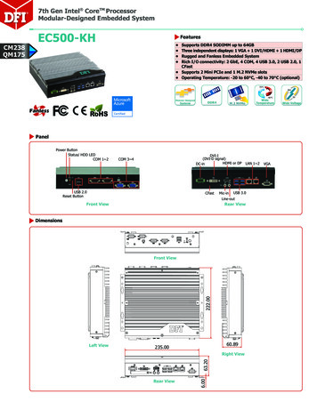
Trephine Core: An Alternative Sinus Lift TechniqueFIGURES 1–6. FIGURE 1. Trephine drill used to create the majority of the implant osteotomy. FIGURE 2. Surgical sequence foruse of the trephine to gain ridge height in the maxilla. FIGURE 3. Trephine diameter in comparison with the implant that willbe placed into the osteotomy created by the trephine demonstrating the osteotomy matches the core diameter of theimplant while allowing the implant threads to engage into the bone when placed. FIGURE 4. Initial radiographdemonstrating root resorption of the overretained deciduous molar. FIGURE 5. Radiograph after extraction of theoverretained deciduous tooth. FIGURE 6. A 5.0 3 10.5-mm threaded fixture (Biohorizons) with an internal hex connector wasselected to fit the intended site.the thread depth). This allows the full depth of theimplant’s threads to engage bone, ensuring primarystability at implant placement (Figure 3). If atapered implant is to be used, we recommend atrephine that is the diameter of the apical of theimplant to be placed to ensure that the crestal halfof the implant engages bone, achieving primarystability. In addition, to avoid overheating the boneand to allow irrigant to flow to the cutting end, it isrecommended that the trephine be used with lightpressure and with a 1–2-mm in-and-out stroke as itsadvanced to the desired depth. We also recommend running the trephine in reverse as it is lesslikely to slip during initial osseous penetration, andif close to the sinus membrane, it decreases thechances of tearing the membrane.The advantages of the trephine technique are asfollows:1 (1) The time required to prepare the lateralwindow is decreased in favor of a crestal approach.(2) A more precise osteotomy can be performed. (3)Depending on the size and anatomy of the sinus,smaller or larger preparation with the various sizesof trephines available can be made. (4) There is noneed for a barrier membrane because the bonysegment acts as a barrier. (5) Use of osteotomes392Vol. XL /Special Issue / 2014allow an improvement in the sites density compared with use of sequential drills.The disadvantages of the trephine technique areas follows:1 (1) A limitation in approach in somepatients is caused by angulation of the trephine. (2)The approach is technique sensitive, but we believethat all existing approaches for sinus elevation arealso technique sensitive.CASE PRESENTATIONA 21-year-old female patient presented with anoverretained upper left second deciduous molarwith clinical mobility. A periapical radiograph wastaken and demonstrated severe root resorption andan absence of a permanent premolar apical to thedeciduous tooth (Figure 4). Treatment options werediscussed with the patient; options included, afterextraction of the deciduous tooth, placement of afixed bridge using an abutment tooth mesial anddistal to the space created, or placement of animplant and restoration with a single crown. Withthe patients projected life span, treatment with animplant would pose the least long-term complications compared with those known for fixed naturaltooth bridges, such as marginal decay of the
Mahesh et alabutment teeth apical to the bridge connectorswith the pontic.The local anesthetic 2% Xylocaine with 1:100 000epinephrine was applied using local infiltration. Thedeciduous tooth was extracted atraumatically usinga periotome. A radiograph was taken to verify noresidual pieces of the deciduous tooth’s rootsremained in the site (Figure 5). A crestal incisionwas made using a #15 scalpel blade to the palatal ofthe crests midline, and a full thickness flap waselevated without the use of releasing incisions.Based on the dimensions of the site, it wasdetermined a 5.0 3 10.5-mm implant would beplaced after site preparation (Figure 6). A trephinewith an internal diameter of 4.0 mm and externaldiameter of 5 mm (Meisenger, Centennial, Colo) wasplaced into the surgical handpiece, and with salineirrigation the osteotomy was initiated at the centerof the existing crest to a depth of 2 mm (Figure 7).The trephine drill was removed from the handpieceand placed into the site. A radiograph was thentaken to verify trajectory of the intended osteotomyand its relation to adjacent anatomical structures(Figure 8). The trephine drill was returned to thesurgical handpiece, and the osteotomy continuedto a depth of 5 mm as measured from the crestalbone (Figure 9). A Buser elevator (Hu Friedy,Chicago, Ill) was used to loosen the trephined coregently from all sides.An offset osteotome (Biohorizons, Birmingham,Ala) with a diameter of 3.2 mm was introduced intothe site, and gentle apical pressure was applied to adepth of 10.5 mm to fracture the trephined core toimprove the bone quality and density of thesurrounding bone of the osteotomy. The osteotomealso aids in elevating the sinus floor atraumaticallyby pushing the bone core to a superior direction(Figure 10). The osteotome was placed into the site,and a radiograph taken to again verify trajectory ofthe site and its relation to anatomical structures(Figure 11).A 5.0 3 10.5-mm internal hex threaded implant(Biohorizons) was introduced into the site at 15 rpmuntil the fixture was seated 75% of its depth.Insertion was then completed using a hand wrenchuntil the fixture was fully seated in relation to thecrestal bone (Figure 12). A radiograph was taken todocument final implant placement that clearlydemonstrates the core lift into the sinus (Figure13). The portion of the flap that would overlay theimplant was denuded of epithelium and thenfolded under the buccal flap to help bulk out thebuccal crestal contour as resorption had resulted ina slight contour defect. The 3-in-1 abutment head(mount, post, abutment) was removed from thefixture and a cover screw was placed. The flap wasthen closed with 4-0 nonresorbable PTFE monofilament suture (Cytoplast, Osteogenics Biomedical,Inc, Lubbock, Tex) using an interrupted technique,and the patient was dismissed with postoperativeinstructions.The patient presented 5 months postsurgicalimplant placement to initiate restoration of theimplant. Examination of the site demonstrated alack of inflammation over the fixture, with slightexposure of the implant cover screw at the center ofthe site and better contours on the buccal aspect ofthe ridge (Figure 14). Local anesthetic was appliedto the crestal soft tissue and a rotary tissue punchwas used to expose the cover screw (Figure 15). Thetissue punch was placed palatal to the midline atthe site in the ideal location restoratively (Figure16). A surgical curette was used to remove the softtissue core and a healing abutment was inserted. Aradiograph was taken to verify complete seating ofthe healing abutment on the implant fixture withno intervening gaps and also to verify integration ofthe implant with the surrounding bone (Figure 17).The patient was dismissed an instructed to usewarm salt water rinses 3–4 times daily for a few daysto aid in healing of the soft tissue surrounding thehealing abutment. After a 2-week healing period,the patient returned to start the restoration (Figure18). The healing abutment was removed and ahealthy soft tissue tunnel was noted over theimplant (Figure 19). An impression head was placedonto the implant, and a closed tray impression wascaptured. A shade was selected to match theadjacent teeth, and the impression was sent tothe lab for fabrication of a screw-retained porcelainfused metal crown. The crown was returned andinserted with a insertion torque on the fixationscrew of 30 Ncm, and then the screw access holewas sealed with a cotton pellet followed bycomposite. Occlusion was checked and adjusted.The patient was seen on regular recall appointments at her general dentist and presented for a 5year follow-up on the implant at the authorspractice. A cone beam computerized tomographyscan had been taken before her recall andJournal of Oral Implantology393
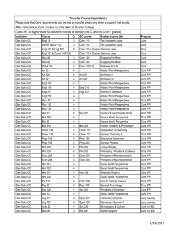
Trephine Core: An Alternative Sinus Lift TechniqueFIGURES 7–14. FIGURE 7. After a full thickness flap, the trephine is used to start the osteotomy. FIGURE 8. Radiograph afterinitial penetration of the trephine into the site to verify the trajectory of the intended osteotomy. FIGURE 9. Osseous corecreated by the trephine. FIGURE 10. An osteotome matching the outer diameter of the trephine is used to finalize theosteotomy created by the trephine after removal of the osseous core. FIGURE 11. Radiograph taken with the osteotome inthe site to verify the trajectory of the osteotomy and its relation to anatomic structures. FIGURE 12. Implant has been placedinto the site created with the trephine, and placement head/stock abutment head is shown still attached to the implant.FIGURE 13. Radiograph at implant placement with placement head on fixture. FIGURE 14. After 5 months of healing, thepatient presented to initiate the restorative phase. The site shows an absence of inflammation and the cover screw can bevisualized.demonstrated maintenance of the crestal bone onthe buccal and palatal as observed in cross section(Figure 20). Clinical examination showed a lack ofgingival inflammation around the restoration (Figure 21), and a periapical radiograph was taken tocompare the interproximal bone levels to theradiograph taken at placement. Radiographic comparison supported the stability of bone over the 5years of function (Figure 22).394Vol. XL /Special Issue / 2014DISCUSSIONOsseointegrated implants have shown a high longterm survival rate since 1965.7 Sinus floor elevationis a technique for extending the application ofimplants, and it was devised for cases in whichimplant placement was difficult due to lack ofadequate bone. Today, this operative method isconsidered to be highly predictable. The choice ofprocedure is often dictated by the amount of
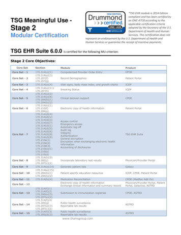
Mahesh et alFIGURES 15–22. FIGURE 15. A rotary tissue punch is used to expose the cover screw in preparation to initiate the restorativephase. FIGURE 16. The rotary tissue punch has created a core of soft tissue in the ideal location on the ridge over theintegrated implant. FIGURE 17. Radiograph of the healing abutment placed on the implant, demonstrating integration of thefixture and an adequate sinus elevation with the infractured core. FIGURE 18. A healing abutment was placed, and tissue wasallowed to mature and heal after exposure of the implant before restoration of the implant. FIGURE 19. Two weeks afterremoval of the soft tissue core created by the tissue punch, the healing abutment was removed and the implant connectorcan be visualized. FIGURE 20. Cone beam computerized tomography cross-sectional view through center of the implant after5 years of function, demonstrating stable bone levels at the apical, buccal, and lingual margins. FIGURE 21. Clinicalphotograph taken 5 years postimplant placement and restoration, demonstrating stable peri-implant soft tissue. FIGURE 22.Radiograph 5 years postimplant placement and restoration, demonstrating stable bone levels with no bone loss.residual crestal bone in the posterior maxilla.7However, irrespective of the procedure chosen,maintaining membrane integrity is important, and itis essential to produce a cavity that will limit theamount of sinus graft material inserted into thezone, thereby improving implant survival andreducing complications.8A systematic review reported an incidence ofmembrane perforation ranging from 0% to 21.4%,and postoperative infection from 0% to 2.5% aftertranscrestal sinus elevation procedures.9 In anexperimental evaluation of maxillary sinus mem-brane response after elevation with osteotometechnique in human cadavers, membrane perforation was observed in 6 of 25 implants (24%), withthe risk being increased with an increasing extent ofsinus floor elevation to be obtained.10 Endoscopicstudies have demonstrated the risk of membraneperforation while performing transalveolar sinusfloor elevation.11 However, according to Engelkeand Deckwer,12 in an endoscopic study, the sinusfloor may be elevated up to 5 mm withoutperforating the sinus membrane. Also, with increasing risk of sinus membrane perforation, the survivalJournal of Oral Implantology395
Trephine Core: An Alternative Sinus Lift Techniquerate of implants is affected. Proussaefs et al13 foundfewer implant survivals for implants installed in agrafted sinus with membrane perforation. Similarly,Hernández-Alfaro et al14 studied the prevalence ofsurgical complications and described an actionprotocol relating to the perforation size. Theydescribe in their results a lower implant survivalrate for implants installed in grafted sinus whenthere was a membrane perforation influenced alsoby perforation size. These results coincided with theresults reported by Viña-Almunia et al15 whoconcluded that the survival of implants diminisheswhen they are placed in sinus lifts with a perforatedmembrane.Use of a trephine provides such a techniquewhere membrane perforation can be avoided. Atthe same time, there is no use of bone graft so thatthe implant is in direct contact with the autogenousbone, accelerating osseointegration through directcontact to implant contact. Fugazzotto16 reported acumulative success rate of 98.0% with this technique after 13–48 months of follow-up.10 In thiscase report, at 5-year follow-up intraoral periapicalradiograph shows excellent peri-implant bone atthe crestal level, and clinically healthy peri-implantsoft tissue can be appreciated without any recession.CONCLUSIONThe use of a trephine allows better preparedosteotomy in less time, making the procedurecomfortable for the clinician and the patient andproviding greater confidence and security. Themembrane perforation risk during osteotomy isminimal, thereby reducing related complications.However, clinician must be experienced in using atrephine and should be used with caution.396Vol. XL /Special Issue / 2014REFERENCES1. Raja SV. Management of the posterior maxilla with sinuslift: review of techniques. J Oral Maxillofac Surg. 2009;67:1730–1734.2. Garg A. Augmentation grafting of the maxillary sinus forthe placement of dental implants: anatomy, physiology, andprocedure. Implant Dent. 1994;8:36–46.3. Thomas GJ. Sinus lifts: a possible solution to the atrophicmaxilla. J Macomb Dent Soc. 1990;29:9–11.4. Tatum H Jr. Maxillary and sinus implant reconstructions.Dent Clin North Am. 1986;30:207–229.5. Smiller DG, Johnson PW, Lozada JL, et al. Sinus lift graftsand endosseous implants. Dent Clin North Am. 1992;36:151–186.6. Emtiaz S, Carames JMM, Pragosa A. An alternative sinusfloor elevation procedure: trephine osteotomy. Implant Dent. 2006;15:171–177.7. Sekine H, Taguchi T, Seta S, Takano M, Takeda T, KakizawaT. Dental implant treatment with different techniques for sinusfloor elevation: a case report. Bull Tokyo Dent Coll. 2007;48:87–91.8. Farré-Pagés N, Augé-Castro ML, Alaejos-Algarra F, Mareque-Bueno J, Ferrés-Padró E, Hernández-Alfaro F. A novel trephinedesign for sinus lift lateral approach. Case report. Med Oral PatolOral Cir Bucal. 2011;16:79–82.9. Tan WC, Lang NP, Zwahlen M, Pjetursson BE. A systematicreview of the success of sinus floor elevation and survival ofimplants inserted in combination with sinus floor elevation. Part II:transalveolar technique. J Clin Periodontol. 2008;35(suppl 8):241–254.10. Reiser GM, Rabinovitz Z, Bruno J, Damoulis PD, Griffin TJ.Evaluation of maxillary sinus membrane response followingelevation with the crestal osteotome technique in human cadavers.Int J Oral Maxillofac Implants. 2001;16:833–840.11. Nkenke E, Schlegel A, Schultze-Mosgau S, Neukam FW,Wiltfang J. The endoscopically controlled osteotome sinus floorelevation: a preliminary prospective study. Int J Oral MaxillofacImplants. 2002;17:557–566.12. Engelke W, Deckwer I. Endoscopically controlled sinus flooraugmentation. A preliminary report. Clin Oral Impl Res. 1997;8:527–531.13. Proussaefs P, Lozada J, Kim J, Rohrer MD. Repair of theperforated sinus membrane with a resorbable collagen membrane:a human study. Int J Oral Maxillofac Implants. 2004;19:413–420.14. Hernández-Alfaro F, Torradeflot MM, Marti C. Prevalenceand management of Schneiderian membrane perforations duringsinus-lift procedures. Clin Oral Implants Res. 2008;19:91–98.15. Viña-Almunia J, Peñarrocha-Diago M, Peñarrocha-Diago M.Influence of perforation of the sinus membrane on the survival rateof implants placed after direct sinus lift. Literature update. Med OralPatol Oral Cir Bucal. 2009;14:133–136.16. Fugazzotto PA. Immediate implant placement following amodified trephine/osteotome approach: success rates of 116implants to 4 years in function. Int J Oral Maxillofac Implants.2002;17:113–120.
implant's threads to engage bone, ensuring primary stability at implant placement (Figure 3). If a tapered implant is to be used, we recommend a trephine that is the diameter of the apical of the implant to be placed to ensure that the crestal half of the implant engages bone, achieving primary stability. In addition, to avoid overheating the .