Transcription
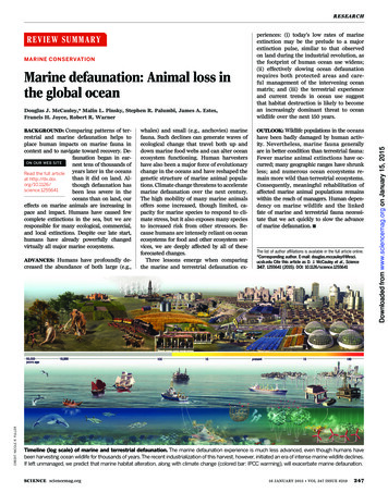
Orbital Marine PowerOrbital O2.2 Tidal TurbineEMEC Berth 6, Fall of Warness, Eday, OrkneyProject Information DocumentFebruary 2021
Document prepared for:Marine Scotland Licensing Operations TeamScottish GovernmentMarine LaboratoryPO Box 101375 Victoria RoadAberdeenAB11 9DBEuropean Marine Energy Centre (EMEC) Ltd.Old AcademyBack RoadStromnessOrkneyKW16 3AWDocument prepared by:Orbital Marine Power Ltd.Innovation Centre – OrkneyHatston Pier RoadKirkwallOrkneyKW15 1ZLContact:James MurrayEmail:J.Murray@orbitalmarine.comRevision record:Revision NumberReviewed byDateRevision Details12James MurrayJames Murray0412202010022021Draft issued for purposes of NRAFor Marine License ApplicationCopyright 2021 Orbital Marine Power LimitedThe Copyright in the document is vested in Orbital Marine Power LimitedFeb 2021Orbital O2.2 Project Information Documenti
CONTENTSGLOSSARY . IV1INTRODUCTION .12PROJECT LOCATION .13OVERVIEW OF THE ORBITAL O2.2 .34MOORING AND ANCHORING SYSTEM . 145PROJECT ACTIVITIES . 226SUMMARY . 32FIGURESFigure 1 Orbital O2.2 in operational mode . 4Figure 2 Orbital O2.2 in transport mode . 4Figure 3 Main internal systems of the Orbital O2.2 . 6Figure 4 Power Take Off configuration of Orbital O2.2 . 8Figure 5 Orbital O2.2 mooring system operating in tide (green lines are 95mm Studlink chain, bluelines are 115mm studlink). 15Figure 6 Orbital O2.2 mooring system at slack tide (green lines are 95mm Studlink chain, blue linesare 115mm studlink) . 15Figure 7. Mooring spring . 16Figure 8 Schematic showing make up of each mooring line . 17Figure 9 Anchor basket with ballast . 18Feb 2021Orbital O2.2 Project Information Documentii
Figure 10 rockbolt . Figure 11 Rockbolt in situ in seabed . 19Figure 12. Scour protection concrete mattress . 19Figure 13 . Orbital O2.2 mooring connector . 20Figure 14 . Multi-cat workboat Green Isle towing SR2000 . 21Figure 15. Multicat temporary 4 point mooring for drilling operation . 25Figure 16. Drilling rig lowered to seabed . 25Figure 17. Orbital Marine Power and HV Contractors offshore on a multi-cat vessel cable jointing or“splicing” operations where static cables are permanently connected to the platform cable whichsupplies power and communications. . 26Figure 18: Multi-functional work vessels such as multi-cats are capable of precise movements ofplatforms in close-quarters and have capacity to tow turbines alongside owing to low well fenderedfree-board. . 27Figure 19: Installation vessel must have capacity for working with 2t buoys in tidal stream during preconnection operations. . 29Figure 20: Site layout planTABLESTable 1. Anchor locations and works extent . 1Table 2 Orbital O2.2 design parameters . 5Table 3 Composition of the mooring lines . 16Table 4 Orbital O2.2 Installation programme . 22Table 5 Location of Orbital O2 anchors . 32Table 6 Permanent anchor and cable details . 32Table 7 Chain and Rope details. 33Table 8. Potential additions to the mooring lines . 33Feb 2021Orbital O2.2 Project Information Documentiii
GlossaryACAlternating CurrentGSMGlobal System for Mobile communicationsHMIHuman Machine InterfacekVKilovolt (1000 volts)LANLocal Area NetworkLEDLight Emitting DiodeMVAMega Volt AmpereMWMegawatt (1,000,000 watts)PLCProgrammable Logic ControllerPTOPower Take-OffRIBRigid Inflatable BoatRPMRevolutions per minuteSCADA Supervisory Control and Data AcquisitionUPSUninterrupted Power SupplyUTM:Universal Transverse MercatorVVoltFeb 2021Orbital O2.2 Project Information Documentiv
1IntroductionOrbital Marine Power Limited seek permission to install, operate and decommission a commercialdemonstrator turbine, the O2.2, at Berth 6 at the EMEC Fall of Warness tidal test site in Eday, Orkney.As part of this project Orbital are required to obtain a new marine from Marine Scotland underSection 20(1) of the Marine (Scotland) Act 2010 to cover the activities associated with the projectnamely “the deposit of a substance or object in the sea or under the seabed”.This Project Information Document is designed to provide Marine Scotland and their consultees withinformation on the project to allow them to consider the application for a new Marine Licence. Thisdocument forms part of the application and is accompanied by the following additional documents: 2Marine Safety Navigational Risk Assessment;Draft Project Specific Environmental Monitoring Plan; andDraft Decommissioning ProgrammeProject locationThe Orbital O2 style unit will be located at EMEC Berth 6 , see Figure 20 (at the end of this document)and connected to the EMEC cable end via ariser umbilical cable as described below. The locationof the proposed anchors is given in Table 1 below.The unit is likely to be installed in summer 2023, with anchor works commencing in summer 2022 atthe earliest. The project would operate up until c. end 2037, with decommissioning in 2038.Table 1. Anchor locations and works extentProposedOrbital O2 Berth6 turbine anchorpositionsAnchorNWCo-ordinatesUniversal TransverseMercator epthCD (m)59 8.790’ N2 49.624’ W35655648659 8.848’ N2 49.468’ W34510259655618759 8.687’ N2 49.241’ W44SW510110655607959 8.629’ N2 49.397’ W35Centre510079655629259 8.744’ N2 49.429’ W34Feb 2021Latitude(WGS84)Orbital O2.2 Project Information Document1
ProposedOrbital O2 Berth6 turbine anchorpositionsAnchorCo-ordinatesUniversal TransverseMercator (UTM)Latitude(WGS84)Longitude(WGS84)NW Works Extent509700655668859 8.9572 49.827NE Works Extent510462655668859 8.9572 49.027SE Works Extent510462655588159 8.5222 49.027SW Works Extent509700655588159 8.5222 49.827Feb 2021Orbital O2.2 Project Information DocumentWaterdepthCD (m)2
3Overview of the Orbital O2.2The Orbital project at the EMEC Fall of Warness tidal test site Berth 6 is composed of the followingmain components: Orbital Marine Power’s turbine, the Orbital O2.2;Anchoring and mooring system; and,Installation, maintenance and decommissioning vessel.This project and asscociated marine license application is separate from the Orbital tidal turbine tobe installed at EMEC Fall of Warness tidal test site Berth 5 in 2021. Henceforce the Berth 5 O2 tidalturbine will be referred to as the O2.1 tidal turbine and the tidal turbine installation at Berth 6 whichthis document covers will be referred to as the O2.2 tidal turbine.The subsea cable connection to shore forms part of the EMEC facility and is therefore not consideredpart of the project. A description of the cable splice and umbilical line connecting the unit with theEMEC cables is included as part of the anchoring and mooring system. It is proposed to use the sameonshore infrastructure as for the Berth 5 O2.1 tidal turbine turbine at the consented EMEC Cauldalefacility. This infrastructure is therefore not discussed further here.3.1Orbital Marine Power’s commercial demonstrator turbine3.1.1Orbital O2.2 overviewOrbital Marine Power’s Tidal Technology is a floating tidal stream energy generator. A cylindricalfloating steel superstructure, which houses power conversion and auxiliary systems, providesreference and attachment for two leg structures with nacelles mounted at their ends. The legstructures have hinge attachments to the superstructure such that, with an actuation system, theycan be lowered to position the nacelles and contra-rotating rotors in the optimal part of the tidalstream resource to generate power or be raised to bring the legs, nacelles and rotors to the surfacefor the purpose of servicing and turbine towing. Station keeping is provided to the superstructurevia a multi-anchor catenary mooring system consisting of rope tethers, mooring chain and anchors.Power is exported from the turbine via a dynamic cable from the superstructure to the seabed whereit connects to seabed static cabling infrastructure that exports power ashore to the EMEC substation.The Orbital O2.2 will have a superstructure of up to 80m length and 3.8m diameter supporting twox c. 1MW rated turbines at the end of each leg structure providing the Orbital O2.2 with a ratedpower of c. 2MW. The generators will reach rated power at current speeds of c. 2.5m/s.Feb 2021Orbital O2.2 Project Information Document3
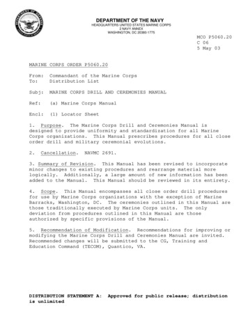
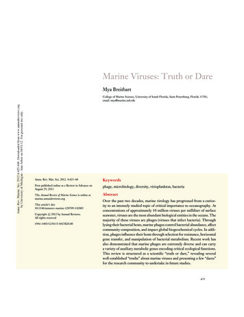
Figure 1Figure 2Orbital O2.2 in operational modeOrbital O2.2 in transport modeTable 2 summarises the main design parameters of the Orbital O2.2 commercial demonstratorturbine.Feb 2021Orbital O2.2 Project Information Document4
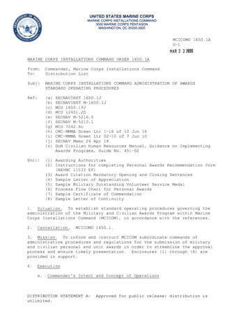
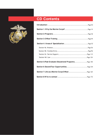
Table 2Orbital O2.2 design parametersSummary of device characteristicsRated powerDisplacementRated current speedCut-in current speedShut down current speedMaximum Hull lengthApproximate Diameter of Hull tubeApprox Depth to uppermost rotor tip during operation (rotors extended)Maximum Depth to bottom rotor tip (deepest point) during operation (rotorsextended)Maximum depth of platform below waterlineHeight of hull tube exposed above the water surfaceMaximum rotation speedMaximum Rotor diameterMaximum Rotor swept area3.1.2c. 2 MW600 metric Tonnes approx.2.5 m/s1 m/s4.5 m/s80 m3.8 m3.2 m25.2 m2.3 m1.5 m15 rpm22 m2 x 380 m2Orbital O2.2 structureThe Orbital O2.2 superstructure platform consists of a main tubular section with conical endscomprised of cathodically protected carbon steel. A deck structure, bollards and fendering for vesseland personnel interaction are attached to the outside. Inside the tube the main PTO equipment suchas converters, transformer, switchgear and C&I panels are mounted on a skid system.The structure is designed to provide sufficient buoyancy and hydrodynamic stability for the turbineto function efficiently. The structure is not permanently manned.The Orbital O2.2 structural components are designed for a 25-year operational lifetime thoughcertain components within the device will have a shorter lifetime. The design & construction of thestructure adheres to a number of DNV-GL and other relevant offshore design standards. Thestructure is designed to survive rare extreme environmental conditions that occur with a very lowprobability, such as a 1 in 100-year wave.Feb 2021Orbital O2.2 Project Information Document5
Figure 3Feb 2021Orbital O2.2 Project Information DocumentMain internal systems of the Orbital O2.26
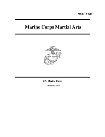
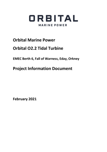
3.1.3NacellesThe Orbital O2.2 has 2 nacelles, one at the end of each retractable leg, which are mounted below thefloating hull of the Orbital O2.2 turbine. The nacelles house the main components of the power takeoff (PTO), i.e. the gearbox, the high speed shaft (HSS), HSS brake and the generator as well assupporting the hub which carries the turbine blades.The Orbital O2.2 nacelles are close to neutrally buoyant and can therefore be floated on andoff the leg for in water assembly and removal for through-life majoroverhaul/maintenance. The nacelles have sufficiently large interiors for personnel access formaintenance & inspection.3.2Pitch unit and rotorsThe Orbital O2.2 turbine features two twin bladed rotors, with blades manufactured from glass-fibrereinforced epoxy. During operation, the rotors rotate in opposing directions to support platformstability. The Orbital O2.2 rotors interface with a dry/non-flooded hub via a rotary pitch bearing.Exterior and interior surfaces exposed to seawater are coated with appropriate antifouling coatings1to avoid permanent build-up of marine growth.The Orbital O2.2 rotors each incorporate a pitching system to control the turbine power output inboth tidal flow directions by adjusting the angles of the 4 blades. The blades rotate by a nominal 180degrees to respond to the diurnal change in tidal current direction and also dynamically feather tomanage torque loads experienced by the machine.3.3Power ConversionThe Power Take-Off (PTO) system applies a controlled torque and speed on the rotor shafts which willextract the maximum amount of energy for a given tidal velocity within given limits. The rotationalenergy of the rotors is converted into electrical energy via a planetary gearbox directly coupled to therotor shaft which steps up the rotational speed of the rotor to a variable speed induction generatorwithin the nacelles. When the power approaches rated, the pitch system begins to vary the bladepitch angle in order to maintain a stable output at rated power.The variable frequency 690V output from each generator in the nacelles is fed to the hull, whereeach circuit is passed through its own generator side converter. Both generator converters feed ontoa common DC bus and into a single grid side converter which converts the DC into 50Hz 690Vac. Thegrid converter feeds through the 690V switchgear and into the main 690/11000V transformer. Theconverter arrangement is shown below.Likely paint choice below waterline 3-875001Feb 2021Orbital O2.2 Project Information DocumentLikelypaintchoiceforblades7
Figure 4Power Take Off configuration of Orbital O2.2A 400V supply to auxiliaries is taken from a separate auxiliary 690/400V transformer.3.4Power distributionThe Power distribution system includes all switchgear and power conversion equipment necessary tosupply all the onboard systems. The Power Distribution system includes the following subsystems: A 24Vdc battery systems to supply Emergency systems including fire detection, Lighting,Control system (PLC, actuators, etc) and Control supply to Generator Variable Speed Drives.A 230V grid supplied system to supply Non-critical systems and systems only required whengenerating.A 400V grid supplied system to supply cooling system components including pumps and fansand Battery chargers for 24V system.A 690V system connected to the PTO Converters.Feb 2021Orbital O2.2 Project Information Document8
3.5Electricity ExportThe Orbital O2.2 will be connected through the subsea power export cable to the Grid. The onboardgeneration voltage will be nominally 690V which will be transformed onboard to 11kV and transmittedover the umbilical to the shore facility.The shore facility will consist of a bank of switchgear and a Pre-Insertion Resistor (PIR). The PIR isrequired due to the weak grid connection at the substation. The turbine onboard transformer isenergised through the PIR to limit the inrush current. If this was not limited, the grid voltage wouldbe depressed for the duration of the inrush, by a factor outwith the limits of ENA P28.The switchgear also allows the subsea cable to be isolated for safety when carrying out offshoreoperations.3.6Auxiliary SystemsThe auxiliary systems onboard the Orbital O2.2 include all equipment and piping related cooling,firefighting and detection systems and are designed in accordance with DNVGL-ST-0164 and DNV-OSD101 guidance for Marine and Machinery Systems and Equipment. Cooling water system - This includes coolant pumps, piping, keel cooler heat exchangers, andany other equipment necessary for the onboard cooling system. Water cooled components inthe hull include the Variable Speed Drives and High voltage transformer. Water cooledcomponents in the nacelle include Gearbox Oil-Water heat exchangers, and generator. Thenacelle water cooling system is self-contained in the nacelle with no requirement to pumpfluids to the main hull. Internal and external lighting - Lighting systems are provided for internal lighting in eachcompartment fed from battery backed supplies, Fire exit/escape route bulkhead lighting,navigational lighting, above sea-surface deck lighting for use during maintenance (e.g.walkway lighting) HVAC - To limit maintenance and reduce potential failure modes, active cooling systems arekept to a minimum, where possible systems rely on passive cooling and componentsdesigned for the marine environment are used. Equipment that is sensitive to dampenvironments are provided with anti-condensation heating when required. This includesmain generators and Variable Speed Drive CabinetsFire detection/fighting system - A fixed fire detection and firefighting system will be installedas per DNV-OD-D101. A detailed fire detection and shutdown procedure will ensure that theOrbital O2.2 will respond in a safe manner on detection of a fire.Charging/Black Start Connector - The Orbital O2.2 has an external connector to allow chargingof internal batteries while the device is off-grid, e.g. from a diesel generator or vessel supply.This allows maintenance and testing of onboard systems without draining the batteries. Thiswill also allow the Orbital O2.2 to be restarted in the case of a long-term loss of mains. Feb 2021Orbital O2.2 Project Information Document9
3.7Corrosion ProtectionThe corrosion protection strategy for all splash zone surfaces will involve cathodic protection inaccordance with DNV-RP-B401 and suitable paint/coatings in accordance with DNV-OS-C401.3.8Orbital O2.2 power supplyThe Orbital O2.2 will contain a 24V battery system, consisting of sealed gelled electrolyte lead acidbatteries which will power the instrumentation and control systems The batteries are charged fromthe 400V auxiliary supply. The 400V system can be supplied by two methods:1. When the Orbital O2.2 is grid connected, the chargers will be supplied from the 690/400Vtransformer. When generating, the energy will comes from the generated power; when notgenerating, the energy will come from the 11kV grid connection2. When the Orbital O2.2 is neither grid connected nor generating (e.g. during towing trials) foran extended period then a diesel backup generator will be employed.3.9Instrumentation and control systemsThe control system for the Orbital O2.2 is designed to be automated via an embedded computer basedsystem, where a software controller will have total control of the Orbital O2.2. This component willmonitor the operating state of the device, reading information from the different sensors and othercomponents and manipulate this information in order to keep the system working within specifiedoperational limits.The operation of the system will be monitored and controlled remotely via a Supervisory Control andData Acquisition (SCADA) system which will run permanently on a dedicated PC located onshore atScotrenewables base in Hatston. This SCADA system will be able, amongst other things, to show theinstantaneous state of the system, acknowledge warnings and alarms from it, give the operator theoption to record them or not and print reports when necessary.The PTO control system will include all systems necessary to control the extraction of energy from thetide. The control system will be flexible to allow for ongoing changes as the project progresses. Asthe Orbital O2.2 is a commercial demonstrator turbine, various sensors will monitor theenvironmental parameters and how the device responds to environmental inputs. This will include: Tidal current speed;Motions in the 6 degrees of freedom;Wave height and period;Rotor torque, speed and thrust;Rotor blade deflection;Mooring line loads;Structural forces; andElectrical power generation.As part of the control system, certain parameters will be monitored solely for the safe and reliableoperation of the Orbital O2.2. These parameters will include:Feb 2021Orbital O2.2 Project Information Document10
Hydraulic pressure, temperature and reservoir levels;Cooling water temperature;Equipment space temperature/humidity;Generator temperature;Generator voltage and current; andBilge level alarms.The operation and monitoring of the system will be undertaken remotely, largely over the internet,by connecting to the SCADA computer located inside the turbine. This configuration minimises thecommunication issues between the PLCs (programmable logic controllers) and the SCADA. The HMI(human-machine) interface will allow operators to perform different operational and safety relatedactions over the system depending on the security level that each operator is given. The SCADAsystem will generate information about the general status of the system via process variables, alarms,reports, etc.Integrated with the main control system, there will be several instruments which will gather importantdata to be used during the real time operation of the machine and to assess the performance of thesystem during the post-processing of the data. Apart from the main sensors that will give feedbackfrom several parts of the system, the following instrumentation will help with safety andenvironmental tasks: 3.10ADCP (Acoustic Doppler Current Profiler) to measure the tidal speed: This will be used duringoperation to control power generation and to make safety decisions;MRU (Motion Reference Unit): Gives information about the motion of the turbine. Also usefulfor safe operations;GPS (Global Positioning System): Monitors the position of the device. Geo-fencing alarms willbe set;Rotor variables (Torque, Speed, Thrust): Sensors give information which will be used to controlgeneration and work within safety limits;Load Shackles: These will measure the tension on the mooring lines for safe operation;Structural forces: Strain gauges will be installed at critical locations on the structure of thedevice to detect stress;Hydraulic pressure: There will be pressure sensors in several parts of the hydraulic and coolingsystems to monitor the adequate operation of those systems. These will be used to detectpossible leaks in this systems;Temperature Sensors: These will ensure that equipment is working within limits and that theenvironment inside the turbine is safe for possible access;Fire and Gas System: This system will inform about fire and gas alarms, ensuring that operationand access are safe;Bilge Pumps: The bilge system will detect any potentially dangerous water levels and start thebilge pumps and warn the operators.Leg retraction systemThe leg retraction system will consist of a simple configuration where each leg will have sensors incharge of detecting if the legs are in the correct positions, i.e. totally retracted or extended in theFeb 2021Orbital O2.2 Project Information Document11
optimum position for operation. The system will have interlocks to prevent the legs being retractedwhen not in their “home” position.The legs retraction system works via the control of the hydraulic pumps and valves in charge of movingthe leg rams. The position of the legs will be given by tilt redundant sensors which will allow theoperator to know the position of the individual legs during their deployment and retraction. Thecontrol system will perform several checks before moving the legs in order to keep this operation safefor personnel and equipment (e.g. ensuring the rotors are stopped and locked in position).3.11Electrical connector controlThe main electrical connection to the Orbital O2.2 is via a pull-in riser connection, where a connector‘can’ is winched up to deck level through a small moonpool. The can is fixed such that a protectivecover can be removed and the turbine-side dry mate connectors can be plugged in. A protective coveris then fixed in place to protect the connectors from the environment. This process will take less than30 minutes.3.12Shut down controlDevice shut down will be fully automated. There will be four shut down scenarios:1. Planned at the end of each tidal cycle;2. Planned at cut out tidal velocity (the velocity above which generation of power is stopped dueto the increased loads and strain on the structure and control system);3. Survival shutdown of rotor above critical sea state; and4. In case of an emergency.There are a number of different shut down processes depending on the circumstances of the shutdown outlined below: 3.13Manual - in this case the operator decides to cease turbine operation or decides what statethey want the turbine to be in e.g. transport mode during maintenance operations;Automated - the turbine control system, based on environmental information, decides if itcan keep generating or not and whether to go into a controlled stop stage;Emergency shutdown - the device, again based on environmental information, decides that itis dangerous to operate and shuts down automatically, going into survival mode (legs up);Emergency stop - the device detects a risky or dangerous situation and stops the rotors,disables the drives and trips any other equipment involved in the movement of the rotors,applying the brakes and waiting for the operator to decide what to do next.Communication systemThe communications system will consist of: Radio Frequency Link: this is a remote but short distance link which is used to perform someactions on the device without the need for personnel on board the device;Feb 2021Orbital O2.2 Project Information Document12
Wireless LAN: this link connects the turbine with the router installed on shore via long rangeaccess points;Wired Ethernet LAN: This link uses a fibre optic connection to shore. This will be the maincommunication link;3G: There will be at least one 3G (or 4G) modem installed in the turbine which can be used asa back-up communication route in case of a failure in the main links;GSM: There will be a GSM system which allows the turbine to send and receive SMS texts. Thissystem will be used to alarm the duty managers about safety related issues in the event of afailure on the internet connection and can receive commands from the duty managers toperform actions on the system. The GSM system is backed up by an UPS (UninterruptiblePower Supply) to ensure that it remains operational in the event of a power failure.Feb 2021Orbital O2.2 Project Information Document13
4Mooring and anchoring system4.1Overview of the mooring systemThe mooring system for the Orbital O2.2 comprises of four catenary mooring lines which aremoored to the seabed via four separate anchors. The mooring system has been designed accordancewith Offshore Standard DNV-OS-E301.Two lines would be connected at both the forward and aft ends of the hull to hold the platform onstation. On each tidal cycle, the platform would be held on station by one of these two lines. As thetide changes direction, the turbine will move by up to 25 m in all directions as slack in the mooringlines is taken up, with the opposite lines then holding the turbine in position. Mooring line lengthswill be subject to detailed design and micrositing but will each be in the region of 225m in length.In the highly unlikely event that a mooring line failed, any single remaining mooring line is capable ofholding the platform in place.The area covered by the mooring spread will be approximately 420m x 220m.Feb 2021Orbital O2.2 Project Information Document14
Figure 5Figure 6Feb 2021Orbital O2.2 mooring system operating in tide (green lines are 95mm Studlink chain, blue lines are 115mm studlink)Orbital O2.2 mooring system at slack tide (green lines are 95mm Studlink chain, blue lines are 115mm studlink)Orbital O2.2 Project Information Document15
4.1.1Composition of Mooring LinesEach mooring line will be predominantly composed of studlink mooring chain.The composition of the mooring lines and approximate length is given below.Table 3Composition of the mooring linesDescriptionLength (m)Weight (kg/m)95mm studlink chain125m200115mm studlink chain1
The Orbital O2.2 turbine features two twin bladed rotors, with blades manufactured from glass-fibre reinforced epoxy. During operation, the rotors rotate in opposing directions to support platform stability. The Orbital O2.2 rotors interface with a dry/non-flooded hub via a rotary pitch bearing.